
Related Manuals for IBA ibaDAQ


Summary of Contents for IBA ibaDAQ
- Page 1 Manual ibaDAQ Central Unit for stand-alone Data Acquisition Manual Issue 1.1...
- Page 2 Inter- net. The current version is available for download on our web site www.iba-ag.com. Windows is a label and registered trademark of the Microsoft Corporation. Other product and ®...
-
Page 3: Table Of Contents
Manual Table of Contents About this manual ................... 6 Target group ....................7 Notations ....................... 7 Used symbols ....................8 Introduction ..................... 9 Scope of delivery................... 11 Safety instructions ..................12 Intended use ....................12 Special safety instructions ................12 System requirements .................. - Page 4 Backplane bus – Digital tab ................. 37 10.3.5 Diagnose signals ..................37 10.4 Configuring inputs ..................40 10.4.1 ibaDAQ – General tab ................. 40 10.4.2 ibaDAQ – Digital tab ..................41 10.5 Configuring outputs ..................42 10.6 Settings for network and FO interface, special functions ......42 10.6.1...
- Page 5 Manual Accessories and related products ............... 65 Index ....................... 67 Contact and Support ..................68 Issue 1.1...
-
Page 6: About This Manual
This manual describes the layout, application and operation of the ibaDAQ unit. ibaDAQ can be used as a central unit in the iba modular system. For a general description of the iba modular system and additional information about layout, application and operation of the modules, please refer to the dedicated manuals. -
Page 7: Target Group
Manual Target group This manual addresses in particular the qualified professionals who are familiar with han- dling electrical and electronic modules as well as communication and measurement tech- nology. A person is regarded as a professional if he/she is capable of assessing safety and recognizing possible consequences and risks on the basis of his/her specialist train- ing, knowledge and experience and knowledge of the standard regulations. -
Page 8: Used Symbols
Manual ibaDAQ Used symbols If safety instructions or other notes are used in this manual, they mean: The non-observance of this safety information may result in an imminent risk of death or severe injury: By an electric shock! Due to the improper handling of software products which are coupled... -
Page 9: Introduction
Calculation of process parameters Modular concept The central unit is the heart of the iba modular system. It can be complemented by up to 4 I/O modules. ibaDAQ is the new smart central unit in the iba modular system that en- ables data acquisition with ibaPDA functionality independent of an external computer. - Page 10 Manual ibaDAQ Figure 1: Example of integration in 2 different networks Issue 1.1...
-
Page 11: Scope Of Delivery
Covering caps for FO cables, USB and Ethernet 8-pin connector with spring terminals (digital inputs and outputs) 2-pin connector with spring terminals (voltage supply) Manual (German and English) "iba Software & Manuals" DVD Issue 1.1... -
Page 12: Safety Instructions
Excess voltage may destroy the device! ATTENTION! Never insert or remove modules and CPU at the subrack under live conditions! Switch off ibaDAQ and disconnect the power supply before inserting or removing mod- ules. Important note Do not open the device! Opening the device will void the warranty! Important note Please shutdown the device properly at any time to prevent dataloss. -
Page 13: System Requirements
ibaPDA client via network link Note The ibaDAQ central unit runs ibaPDA by default. The license for 64 signals is included in the delivery. The number of signals can be extended up to 1024 with additional license. The selection of I/O modules to be used in ibaMBox is limited, see chapter 11.4. -
Page 14: Mounting, Connecting, Dismounting, First Configuration
4. Pull the device off the subrack. Operation with ibaMBox The ibaMBox mobile measuring system is based on the iba modular system that is inte- grated in a compact, rugged aluminum case. The central unit and the I/O modules are already installed in ibaMBox according to the order. -
Page 15: First Configuration
In the factory setting of the network interface, DHCP is active (position of rotary switch S1 = 1). Thus, an IP address is automatically assigned to ibaDAQ, as soon as the device is connected to a network with a DHCP server. If the IP configuration is successful, ibaDAQ can be accessed via the host name daq-<serial number>, e. -
Page 16: Set Up Via Monitor, Keyboard And Mouse
Figure 3: Run dialog (Windows 10) In the field “Computer”, enter the host name or the IP address of the ibaDAQ system. Figure4: Remote Desktop Connection If you are requested to enter login information, use the information given in chapter 7.9. -
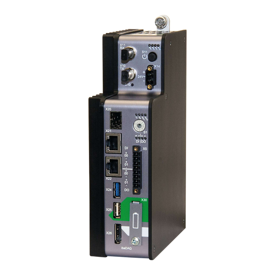
Page 17: Device Description
Manual Device description Views Status display ON/OFF switch S11 Connector for 24 V power supply X14 Display (operating status, user-defined) Rotary switch S1 Display of digital inputs and outputs Connectors of digital inputs and outputs X5 Battery compartment X30... -
Page 18: Operating State And User-Defined Displays
Manual ibaDAQ Important note Contact the iba support when the error LED indicates a fault. 7.2.2 Operating state and user-defined displays Multi-colored LEDs (Lic and Dat) indicate the status of the license and of data recording. It is possible to assign signals to 2 multi-colored LEDs in ibaPDA to display user-defined states. -
Page 19: Operating Elements
Procedure: 1. First, set switch S1 to position 1 and establish a connection between the ibaPDA client and ibaDAQ. To do so, start the ibaPDA client on your PC and follow the steps in chapter 10.1. 2. Set switch S1 to position 0. -
Page 20: System Function Pushbutton S10
FO cable connections X10 and X11 The optical fiber (FO) ports X10 and X11 have the function of an ibaFOB-io card. They allow additional iba devices to be connected such as the ibaPADU family, iba bus moni- tors or system interface connections. -
Page 21: Network Connection X21, X22
Manual All current ibaNet protocols are supported: 2Mbit 3Mbit 5Mbit 32Mbit 32Mbit Flex 7.4.2 Network connection X21, X22 You can connect the device to Ethernet networks via network interfaces X21 and X22. Settings for the IP address can be made at the rotary switch S1. -
Page 22: Pin Assignment
Manual ibaDAQ 7.5.1 Pin assignment Connection Digital input 00 + DI 00 Digital input 00 − Digital input 01 + DI 01 Digital input 01 − Figure 8: Connection diagram for digital inputs and outputs X5 7.5.2 Debounce filter inputs There are four debounce filters for each digital input. - Page 23 Manual Figure 9: Debounce filter: "Stretch rising edge" "Stretch falling edge" The first falling edge sets the output signal (green) to logical 0 and it remains logical 0 for the set debounce time. Subsequently, the channel is transparent again and waits for the next falling edge.
-
Page 24: Digital Outputs
Manual ibaDAQ Figure 12: Debounce filter: "Delay both edges" Digital outputs Connection Digital output 00 + DO 00 Digital output 00 − Digital output 01 + DO 01 Digital output 01 − 7.6.1 Alarm function If the watchdog function is enabled in ibaPDA, the output DO 00 can be configured as an alarm output. -
Page 25: Battery Compartment X30
User Password Administrator xadmin Note By default, the user daq is set to automatically log in. Important note Change the default passwords after you have started up ibaDAQ! This makes unauthor- ized use of the system more difficult. Issue 1.1... -
Page 26: System Integration
Figure 14: Configuration with ibaPDA client The ibaPDA client is connected to the central unit via Ethernet. Configuration of the central unit Figure 15: ibaDAQ with input devices The monitor, mouse and keyboard are connected directly to the central unit. Remote Desktop Figure 16: Configuration via Remote Desktop ... -
Page 27: Connection To Networks
Manual Connection to networks ibaDAQ can be operated in two different networks to separate for example the network for measuring data transmission from the rest of the network. For this prupose the device provides 2 Ethernet interfaces. For setting the addresses in the networks, please refer to chapter 7.3.2. -
Page 28: Supported Ibanet Communication Protocols
The UPS should be designed in such a way that the system is buffered for at least 5 minutes. The digital input DI00 of the ibaDAQ device needs to be configured appropriately for this function in ibaPDA. For further references, see chapter 10.4.1. - Page 29 Manual 8.7.1.2 Measured data acquisition with 32Mbit protocol Figure 22: Unidirectional connection of 32Mbit devices 8.7.1.3 Measured data acquisition with 32Mbit Flex protocol Figure 23: 32Mbit Flex devices in a ring topology Figure 24: Connection of ibaBM-DP Issue 1.1...
-
Page 30: Updates
Do not switch off the device during an update. This might damage the device. Installing an update can take several minutes. Open the ibaPDA I/O Manager and navigate to the main node of your ibaDAQ sys- tem. Click the <Write firmware> button on the "Info" tab and select the "daqs_v[xx.yy.zzz].iba"... - Page 31 If a module is not yet known (i.e. it is more recent than the central unit's firmware version), it will be ignored and not displayed in ibaPDA. In this case, a new update file has to be installed for the "overall release version". Con- tact the iba Support. Issue 1.1...
-
Page 32: Configuration In Ibapda
Selecting the ibaPDA server Address In the "Address" box enter the name or the IP address of the ibaDAQ device. The name is composed of the DAQ-<six-digit serial number>. The serial number is found on the device name plate. -
Page 33: Adding I/O Modules
Manual For further configuration activities, open the I/O Manager as described in the next chap- ter. 10.2 Adding I/O modules Start ibaPDA, open the I/O Manager and proceed as follows: 1. Select the "Backplane bus" link in the I/O Manager. Right-click the link to open a submenu. - Page 34 "General" tab. The connected modules are detected automatically and displayed in the signal tree. 6. Configure ibaDAQ and the modules, e.g. assign a name, debouncing, etc. (see chap- ter 10.3.1 "Backplane bus – General tab" and following).
-
Page 35: General Settings
You can enter a module name. Timebase Specifies the acquisition time base used for ibaDAQ and the connected modules. Use name as prefix If "True" is selected, the module name is prefixed to the signal names of this mod- ule. -
Page 36: Backplane Bus - Diagnostics Tab
Manual ibaDAQ If this attempt is successful, the measurement is restarted automatically with the en- abled module. If this option is not enabled, ibaPDA will not start the measurement if it cannot establish a connection to the device. More functions ... -
Page 37: Backplane Bus - Digital Tab
The "Digital" tab is only displayed when acquisition with digital input modules has been started. The list shows the configured digital signals of ibaDAQ and the digital input modules and the current values. Figure 30: Backplane bus module – Digital tab 10.3.5... - Page 38 Manual ibaDAQ Figure 31: Add the Diagnostics module 10.3.5.1 Diagnostics – General tab Figure 32: Diagnostics module – General tab Basic settings Module type, Locked, Enabled, Name, Timebase, Use name as prefix see chapter 10.3.1. Module No. Logical module number for the unambiguous referencing of signals, e.g. in expres- sions and ibaAnalyzer.
- Page 39 Manual 10.3.5.2 Diagnostics – Digital tab In the “Digital” tab, you can activate the diagnostic signals. Figure 33: Diagnostics module – Digital tab Signal Meaning Hardware state X[…] Module on slot X[…] is OK Hardware available X[…] Module on slot X[…] was detected and initialized...
-
Page 40: Configuring Inputs
Logical module number to reference signals unambiguously, e.g. in expressions and ibaAnalyzer. Digital I/O DI00: Automatic shutdown TRUE: ibaDAQ is shut down automatically if DI00 is set. DO00: Watchdog output TRUE: If ibaPDA cannot read data from the ibaDAQ hardware during acquisition, DO00 is set. Issue 1.1... -
Page 41: Ibadaq - Digital Tab
Manual 10.4.2 ibaDAQ – Digital tab Figure 35: ibaDAQ module – Digital tab Name Click the icon in the name field to enter a signal name and additionally two comments. Debounce filter In the dropdown menu, you can choose the operating mode for the debounce filter. -
Page 42: Configuring Outputs
Used to enable or disable the signal. 10.6 Settings for network and FO interface, special functions The following settings are made in the main branch of ibaDAQ: Configuration of the FO interface, see chapter 10.6.1 Network settings of the device, see chapter 10.6.2 ... -
Page 43: Ibadaq - Configuration Tab
Manual 10.6.1 ibaDAQ – Configuration tab Figure 37: ibaDAQ main node – Configuration tab Interrupt mode The interrupt mode can be set here. Master mode internal (the device is the interrupt master itself) Master mode external (external interrupt master) The option "in use"... -
Page 44: Ibadaq - Info Tab
Write firmware This button allows running firmware updates. Select the update file "daqs_v[xx.yy.zzz].iba" in the browser and start the update by clicking <Ok>. Important note This process may take several minutes and must not be interrupted. After an update, the device driver and the ibaPDA service will restart automatically. - Page 45 This is only possible directly at the device and not via the ibaPDA client. If you run ibaDAQ in a domain, you may ask the IT department to assign the authoriza- tions. PDA1/2 LED Here you can assign signals to the LEDs PDA1 and PDA2.
-
Page 46: Connection Of An External Iba-Device
10.6.3 Connection of an external iba-device For measured data acquisition, an external iba device can be connected to the FO input and output. To integrate the device in ibaPDA, right-click the link „Fiber optic link“ and select „Auto- detect“. The device and the used ibaNet protocol will be automatically detected and dis- played in the module tree. -
Page 47: Fo Link - Info Tab
Manual 10.6.4 FO link – Info tab The left-hand part of the "Info" tab shows information on FO communication. The dis- played information depends on the protocol used. 10.6.4.1 3Mbit protocol Figure 41: FO link with 3Mbit protocol "Link" area ... - Page 48 Manual ibaDAQ FO signal strength This is the difference between the maximum value and the minimum value received from the FO unit. It can be 255 max. The higher this value, the stronger the FO in- put signal. Device ID The ID of the last device in an FO series connection at this FO interface.
- Page 49 Manual DMA buffer size Size of the DMA buffer for this interface. DMA buffer element size Size of the elements in the DMA buffer. 10.6.4.2 5Mbit protocol Figure 42: FO link with 5Mbit protocol The screenshot above shows the information you receive when the FO link operates with 5Mbits, e.g.
- Page 50 Manual ibaDAQ 10.6.4.3 32Mbit protocol Figure 43: FO link with 32Mbit protocol For the display, see 3Mbit protocol. 10.6.4.4 32Mbit Flex protocol Figure 44: Link information for 32Mbit Flex protocol The screenshot above shows the information you see when the link is in 32Mbit Flex mode.
-
Page 51: Link - Configuration Tab
Flex devices, but not change the configuration. Since ibaDAQ has an integrated ibaPDA sys- tem, the device can equally be operated as master or slave in mirror mode. - Page 52 3o-D device. One FO output of ibaBM-FOX-3o-D is connected to the FO input of the ibaPDA master (ibaDAQ in the example) and of the ibaPDA slave. This connection allows the ibaPDA slave to still acquire data when the ibaPDA master has been shut down.
- Page 53 Manual 3 settings are available for mirror mode: Disabled: The data is not mirrored so that this ibaPDA system is the only system capable of configuring the devices and acquiring data. Master: This ibaPDA system configures the Flex devices on the link. The data and the device configurations are mirrored so that other ibaPDA systems can also ac- quire the data.
- Page 54 Manual ibaDAQ Figure 50: Simulation of the bandwidth distribution in the 32Mbit Flex telegram. The data size in bytes of each device on the link and the timebase of the data acquisition on the link (in µs) is needed for the calculation.
- Page 55 Manual Set the smallest scheduled sampling rate in the "Timebase" field. Now, you can enter the scheduled or expected data volume (in bytes) manually in the table rows 1 to 15. Each new entry causes the result values in the "Flex frame utilisation" field to be recalculated.
-
Page 56: Setting Up File Sharing
Figure 53: Sharing folders Note When running ibaDAQ in a so-called workgroup, you need the user name and the pass- word to access it. If ibaDAQ and the accessing PC are in the same domain, a separate authentication is usually not necessary. -
Page 57: Technical Data
Manual Technical data 11.1 Main data Brief description Description ibaDAQ Description Central unit for stand-alone data acqusition Order number 10.170001 Processor unit Processor Intel Atom E3845 quad core CPU 1.91 GHz Operating system Windows 10 IoT Enterprise x64 4 GB Flash memory Solid state drive 256 GB (SN <... -
Page 58: Interfaces
Manual ibaDAQ 11.2 Interfaces ibaNet ibaNet protocols ibaNet 32Mbit Flex (bidirectional) ibaNet 32Mbit 50µs / 100µs / 800µs ibaNet 5Mbit ibaNet 3Mbit ibaNet 2Mbit FO cable 2 ST plug connectors (62.5/125 µm) for RX and TX; max. 2000 m cable length without repeater... -
Page 59: Supported I/O Modules
Manual OFF resistance (log. 0) min. 100 MΩ Electrical isolation 2.5 kV AC Channel-channel 2.5 kV AC Channel-housing Connection technology Screw-type terminal (0.14 mm to 1.5 mm ), screw connection, included in delivery 11.4 Supported I/O modules I/O module Order no. -
Page 60: Dimensions
Manual ibaDAQ 11.5 Dimensions ibaDAQ (Dimensions in mm) Figure 54: Dimensions of ibaDAQ (Dimensions in mm) Figure 55: Dimensions of ibaDAQ with cables Issue 1.1... - Page 61 Manual Distance between 2 central units (Dimensions in mm) Figure 56: Minimum distance between 2 central units Issue 1.1...
- Page 62 Manual ibaDAQ Mounting plate 19" (Dimensions in mm) Figure 57: Dimensions of 19" mounting plate Issue 1.1...
- Page 63 Manual Subrack ibaPADU-S-B4S with mounting brackets (Dimensions in mm) Figure 58: Dimensions of mounting bracket with ibaPADU-S-B4S Subrack ibaPADU-S-B1S for one central unit and one module (Dimensions in mm) Figure 59: Dimensions ibaPADU-S-B1S Issue 1.1...
-
Page 64: Connection Diagram
Manual ibaDAQ Subrack ibaPADU-S-B for one central unit (Dimensions in mm) Figure 60: Dimensions ibaPADU-S-B 11.6 Connection diagram 11.6.1 Pin assignment voltage supply X14 Connection + 24 V 11.6.2 Pin assignment digital inputs and outputs X5 Connection Digital input 00 +... - Page 65 Manual Accessories and related products Subrack ibaPADU-S-B4S Order number 10.124000 Backplane module to accommodate 1 central unit with up to 4 I/O modules W x H x D: 229 mm x 219 mm x 27 mm Fitting equipment included...
- Page 66 Manual ibaDAQ Mounting plate 19“ for PADU-S modular Order number 10.124005 Mounting plate (483 mm/19“) for up to 2 ibaPADU-S-B4S backplanes Mounting of 1 backplane module centered or 2 backplane modules left and right Mounting equipment included Module carrier for ibaPADU-S modular system Order number 10.124007...
- Page 67 Manual Index Automatic shut down user-defined display Battery compartment Mirror mode with 32Mbit Flex Configuration Mobile measuring system directly at device with an external ibaPDA client Configuring outputs Network connection Network settings in ibaPDA Debounce filter configure in ibaPDA...
- Page 68 Mailing address iba AG Postbox 1828 D-90708 Fuerth Germany Delivery address iba AG Gebhardtstrasse 10 D-90762 Fuerth Germany Regional and Worldwide For contact data of your regional iba office or representative please refer to our web site www.iba-ag.com. Issue 1.1...
Need help?
Do you have a question about the ibaDAQ and is the answer not in the manual?
Questions and answers