
Subscribe to Our Youtube Channel
Related Manuals for IBA ibaDAQ-C


Summary of Contents for IBA ibaDAQ-C
- Page 1 Manual ibaDAQ-C Compact Device for stand-alone Data Acquisition Manual Issue 1.4...
- Page 2 Inter- net. The current version is available for download on our web site www.iba-ag.com. Windows is a label and registered trademark of the Microsoft Corporation. Other product and ®...
-
Page 3: Table Of Contents
Manual Table of Contents About this manual ................... 5 Target group ....................5 Notations ....................... 5 Used symbols ....................6 Introduction ..................... 7 Scope of delivery................... 10 Safety instructions ..................11 Intended use ....................11 Special safety instructions ................11 System requirements ..................12 Hardware .................... - Page 4 Manual ibaDAQ-C ibaDAQ-C configuration ................25 9.2.1 Configuration tab ..................25 9.2.2 ibaDAQ-C – Info tab ..................26 Add modules ....................28 Setting up file sharing .................. 29 9.4.1 Troubleshooting ..................30 Technical data ....................32 10.1 Main data ....................32 10.2...
-
Page 5: About This Manual
Manual About this manual This manual describes the layout, application and operation of the ibaDAQ-C device. Target group This manual addresses in particular the qualified professionals who are familiar with han- dling electrical and electronic modules as well as communication and measurement tech- nology. -
Page 6: Used Symbols
Manual ibaDAQ-C Used symbols If safety instructions or other notes are used in this manual, they mean: The non-observance of this safety information may result in an imminent risk of death or severe injury: By an electric shock! Due to the improper handling of software products which are coupled... -
Page 7: Introduction
Manual Introduction ibaDAQ-C can be used as stand-alone unit to acquire and record data. ibaDAQ-C inte- grates a complete ibaPDA system, an internal solid state disk (SSD) with sufficient memory space and powerful integrated Intel®-Atom™-CPU. The extremely slim and ro- bust compact unit is designed to fit into the extremely confined space of control cabinets, test stands, cranes, etc. - Page 8 Connection to several networks With the two independent 1Gbit/s Ethernet interfaces, ibaDAQ-C can operate in two net- works and thus enable the separation of IT and process networks. This separation al- lows, for example, databases and storage systems to be connected to ibaDAQ-C, which are located in the IT network.
- Page 9 Generic-TCP/IP protocol communication interface Generic-TCP Other documentation For the description and configuration of ibaPDA and the interfaces of ibaPDA-PLC- Xplorer please refer to the corresponding manuals. You find the manuals on the DVD “iba Software & Manuals” included in delivery. Issue 1.4...
-
Page 10: Scope Of Delivery
Covering caps for USB and Ethernet 2-pin connector with spring terminals (digital input, to initiate shutdown by UPS) 3-pin connector with spring terminals (voltage supply) Manual (German and English) "iba Software & Manuals" DVD Issue 1.4... -
Page 11: Safety Instructions
The device is an electrical apparatus. It is only allowed to use the device for the following applications: Measurement acquisition Applications with iba products (ibaPDA, and others) The device must only be used as described in chapter 10 Technical data. Special safety instructions Strictly observe the operating voltage range! Never supply the device with a voltage other than 24 V DC ±10%! -
Page 12: System Requirements
ibaPDA client via network link Note The ibaDAQ-C central unit runs ibaPDA by default. The license for 64 signals is included in the delivery. The number of signals can be extended up to 1024 with additional license. Issue 1.4... -
Page 13: Mounting, Dismounting, First Configuration
If the IP configuration is successful, ibaDAQ-C can be accessed via the host name daq-c-<serial number>, e. g. daq-c-000002. If the network does not have a DHCP server, ibaDAQ-C can be set to fixed IP addresses via the rotary switch S1 position = 2: Network interface X21: 192.168.1.1... - Page 14 “ibaPDA server selection” and enter the host name or the IP address of ibaDAQ-C as address. By default, the port number is 9170. If ibaDAQ-C is already in the list of servers, you can also select the device there.
-
Page 15: Set Up Via Monitor, Keyboard And Mouse
For further configuration, proceed as described in chapter 9. 6.3.2 Set up via monitor, keyboard and mouse Connect a monitor to the DisplayPort connection of ibaDAQ-C. If necessary use an adapter. Connect a keyboard and a mouse to the USB ports of ibaDAQ-C. -
Page 16: Device Description
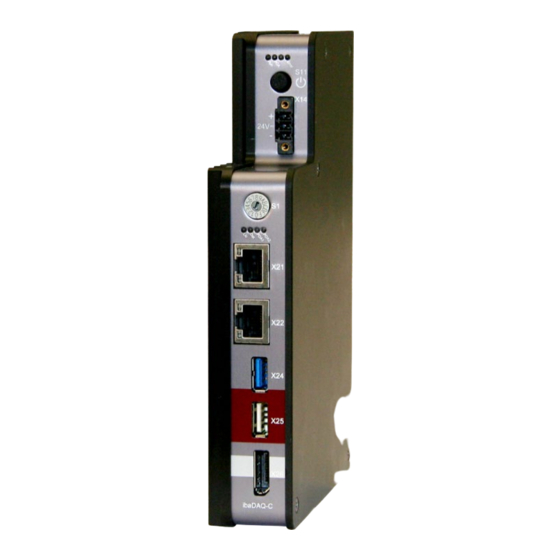
Manual ibaDAQ-C Device description Views Status display ON/OFF switch S11 Connector for 24 V power supply X14 Rotary switch S1 Display (operating status, user-defined) Network port X21 Network port X22 USB 3.0 port X24 USB 2.0 port X25 Monitor connection X26... -
Page 17: Display Elements
Error No error Hardware error Important note Contact the iba support when the error LED indicates a fault. 7.2.2 Operating state and user-defined displays Multi-colored LEDs (Lic and Dat) indicate the status of the license and of data recording. It is possible to assign signals to 2 multi-colored LEDs in ibaPDA to display user-defined states. -
Page 18: Operating Elements
Procedure: 1. First, set switch S1 to position 1 and establish a connection between the ibaPDA client and ibaDAQ-C. To do so, start the ibaPDA client on your PC and follow the steps in chapter 9.1. 2. Set switch S1 to position 0. -
Page 19: Communication Interfaces
"Use DHCP" for X21. For X22, uncheck "Use DHCP" and enter a fixed IP ad- dress that matches your network. Click on <Apply settings> to activate the settings. Figure 6: ibaDAQ-C, “Info” tab Communication interfaces 7.4.1 Network connection X21, X22 The X21 and X22 network connections allow you to integrate the device into an Ethernet network. -
Page 20: Voltage Supply X14
Manual ibaDAQ-C The polarity, as well as the type of voltage at connector X5 is not important. Only the potential difference of >4 V is relevant, because the signal from X5 is internally routed via a rectifier. Figure 7: Example of internal wiring... -
Page 21: User Accounts
User Password Administrator xadmin Note By default, the user daq is set to automatically log in. Important note Change the default passwords after you have started up ibaDAQ-C! This makes unau- thorized use of the system more difficult. Issue 1.4... -
Page 22: System Integration
The ibaPDA client is connected to ibaDAQ-C via Ethernet. Configuration with input devices Figure 10: ibaDAQ-C with input devices The monitor, mouse and keyboard are connected directly to ibaDAQ-C. Remote Desktop Figure 11: Configuration via Remote Desktop Operation through the network using Remote Desktop... -
Page 23: Connection To Networks
For this purpose, the digital output of the UPS serves as signal for securely shut- ting down the ibaDAQ-C operating system. The UPS should be designed in such a way that the system is buffered for at least 5 minutes. -
Page 24: Configuration In Ibapda
Selecting the ibaPDA server Address In the "Address" box enter the name or the IP address of the ibaDAQ-C device. The name is composed of the DAQ-C-<six-digit serial number>. The serial number is found on the device name plate. -
Page 25: Ibadaq-C Configuration
Configuration tab Figure 16: ibaDAQ-C – Configuration tab ibaPDA uses only the ibaDAQ-C hardware as interrupt source. When "In use" is disabled, ibaPDA uses the less accurate internal timer. The illustration of the device displays the current state of the LEDs and the hex switch. -
Page 26: Ibadaq-C - Info Tab
Write firmware This button allows running firmware updates. Select the update file "daqc_v[xx.yy.zzz].iba" in the browser and start the update by clicking <Ok>. Important note This process may take several minutes and must not be interrupted. After an update, the device driver and the ibaPDA service will restart automatically. - Page 27 This is only possible directly at the device and not via the ibaPDA client. If you run ibaDAQ-C in a domain, you may ask the IT department to assign the authori- zations. PDA1/2 LED Here you can assign signals to the LEDs PDA1 and PDA2.
-
Page 28: Add Modules
Manual ibaDAQ-C Add modules Data acquisition requires additional communication interfaces. The interfaces ibaPDA- Interface-MQTT and ibaPDA-PLC-Xplorer are already included in the standard scope of delivery. Further communication interfaces require a separate license. If you have li- censed additional communication interfaces, they appear as nodes in the tree structure. -
Page 29: Setting Up File Sharing
Sharing folders Note When running ibaDAQ-C in a so-called workgroup, you need the user name and the password to access it. If ibaDAQ-C and the accessing PC are in the same domain, a separate authentication is usually not necessary. Issue 1.4... -
Page 30: Troubleshooting
Manual ibaDAQ-C 9.4.1 Troubleshooting If you cannot access the shared directory from another system, file and printer sharing may not be enabled. You can activate it as follows. 1. Right-click the network icon in the notification area of the taskbar to open the “Net- work and Sharing Center”. - Page 31 Manual 3. Select the profile you are using. This is indicated by the addition "(current profile)". 4. Make sure that the "Turn on network discovery" and "Turn on file and printer sharing" settings are enabled. Issue 1.4...
-
Page 32: Technical Data
Manual ibaDAQ-C Technical data 10.1 Main data Brief description Name ibaDAQ-C Description Compact device for stand-alone data acqusition Order number 10.170002 Processor unit Processor Intel Atom E3845 quad core CPU 1.91 GHz Operating system Windows 10 IoT Enterprise x64 4 GB Flash memory Solid state drive 128 GB (SN: <... -
Page 33: Interfaces
Manual 10.2 Interfaces Communication interfaces Ethernet 2x RJ45, 1 Gbit/s 1x USB 3.0, 1x USB 2.0 DisplayPort Port for monitor Digital input Number Version Electrically isolated, protected against polarity reversal Max. input voltage ±60 V permanent Signal level log. 0 >... -
Page 34: Dimensions
Manual ibaDAQ-C 10.3 Dimensions ibaDAQ-C (Dimensions in mm) Figure 22: Dimensions of ibaDAQ-C Issue 1.4... -
Page 35: Connection Diagram
Manual 10.4 Connection diagram 10.4.1 Pin assignment voltage supply X14 Connection + 24 V Earth 10.4.2 Pin assignment digital input X5 Connection Digital input 00 + Digital input 00 - Issue 1.4... -
Page 36: Index
Manual ibaDAQ-C Index user-defined display Battery compartment Network connection Network settings Configuration in ibaPDA directly at device with an external ibaPDA client Power supply Display operating state Restart DisplayPort X26 Rotary switch file sharing USB ports Firmware updates User accounts... -
Page 37: Contact And Support
Mailing address iba AG Postbox 1828 D-90708 Fuerth Germany Delivery address iba AG Gebhardtstrasse 10 D-90762 Fuerth Germany Regional and Worldwide For contact data of your regional iba office or representative please refer to our web site www.iba-ag.com. Issue 1.4...
Need help?
Do you have a question about the ibaDAQ-C and is the answer not in the manual?
Questions and answers