
Subscribe to Our Youtube Channel
Related Manuals for UAS CLARCOR Smog-Hog SHN-10


Summary of Contents for UAS CLARCOR Smog-Hog SHN-10
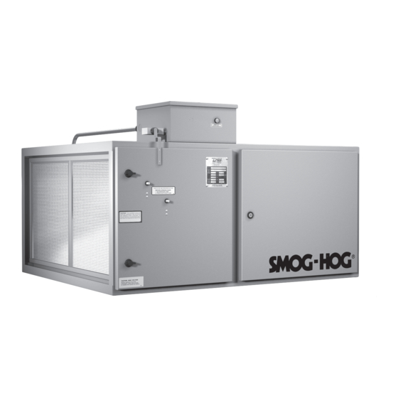
- Page 1 OWNER'S MANUAL Smog-Hog Electrostatic Precipitator ® l models: sHN-10, sHN-20, sHN-40 ANd sHN-50 Model SHN-20 Shown...
- Page 2 Should you need assistance, call the United Air Specialists, Inc. customer service number shown below. To expedite your service, have the following information available when contacting UAS. UAS ORDER #: ________________________________________________________________ UNIT MODEL #:________________________________________________________________...
-
Page 3: Table Of Contents
TABLE OF CONTENTS Page Safety PrecautionS ..................ii Smog-Hog nomenclature ..................1 1. inSPection note .....................1 2. inStaLLation PLanninG ..................2 a. unducted or area capture ................2 B. Ducted or Source capture ................2 c. access clearance ..................2 3. inStaLLation .....................2 a. unit Mounting ....................2 B. -
Page 4: Safety Precautions
SAFETY PRECAUTIONS We have provided many important safety messages in this manual on your Smog-Hog SHn. always read and obey all safety messages. this is the safety alert symbol. this symbol alerts you to potential hazards that can kill or hurt you and others. all safety messages will follow the safety alert symbol and the word “DanGer”... - Page 5 SMoG-HoG revised 09/15 ® SHn Series Models Smog-Hog Electrostatic Precipitator ® Installation and Service...
-
Page 6: Smog-Hog Nomenclature
Because it is necessary to develop proper airflow patterns, the placement and number of precipitators SHN - SMoG-HoG n-Series should be as suggested by uaS or your local 10 - airflow in 100s of cfM (i.e., 10 @ 1,000 cfM, etc.) representative. -
Page 7: Metal Truss Supported Ceilings
C. Column or Wall Mounting. figure 2 shows an contaminant capture and even dispersion of clean air. SHn-50 (t-shaped) unit suspended from a the pattern should be suggested by uaS or your local cantilevered frame from which the 1⁄2” threaded representative. -
Page 8: Motor/Blower Checkout
Units are factory wired for the voltage requirement within the cabinet. indicated to uaS by the customer. the electrical box has knockouts. Therefore, whatever electrical connectors are standard in your plant may be used Single-phase units (i.e. - Page 9 SMoG-HoG revised 09/15 ® SHn Series Models SHN-10 Dimensions and Mounting Hole Locations SHN-20...
- Page 10 SMoG-HoG revised 09/15 ® SHn Series Models SHN-40 Dimensions and Mounting Hole Locations SHN-50-T...
-
Page 11: Description Of Components
Power consumption is 75 watts maximum. The power supply is located in an external electrical box. G. Push-to-Test Buttons. An exclusive UAS feature, these buttons verify electrical continuity during equipment operation without the use of a meter. They... -
Page 12: Maintenance
SMoG-HoG revised 09/15 ® SHn Series Models THE FOLLOWING SECTIONS ARE FOR THE USE OF TRAINED PERSONNEL ONLY CAUTION CAUTION Hazardous live and moving parts are exposed during risk of electrical shock. a residual Dc voltage will remain the following procedures. Switch off/isolate the electrical on high voltage components for a short time after power is supply to the Smog-Hog air cleaning System before removed. -
Page 13: Component Cleaning Methods
Guidelines for mixing, heating and expected uaS and/or our local representatives can provide results are included on detergent specification sheets. assistance in choosing the best method for cleaning Smog-Hog components in your application. -
Page 14: Periodic Maintenance And Adjustment
SMoG-HoG revised 09/15 ® SHn Series Models 6. Blower has been checked for heavy buildup, clean if required. Blower housing drain is open (when provided). 7. If so equipped, preconditioning accessories (vee-bank filters, cooling coils, etc.) have been checked for excessive pressure drop, clean if required. 10. -
Page 15: Airflow Adjustment
• A flashing indicator light indicates a failure in the high improper Blower Speeds adversely affect System voltage circuits. Performance. contact uas Before adjusting Motor Variable Pulley Settings. there are four conditions which may cause a flashing indicator light. - Page 16 SMoG-HoG revised 09/15 ® SHn Series Models there will be continuous cell arcing if cell voltages exceed 7.5 KVDC. This is also caused by “run away” voltages to the power pack requiring power pack replacement. a high voltage measurement can be performed by removing both the high voltage wires from the power pack to determine high voltage output.
- Page 17 SMoG-HoG revised 09/15 ® SHn Series Models which requires correct wiring polarity since the • Deformed collector cell contact springs contacting a power pack output is Dc voltage. the LeD will “grounded surface,” including cabinet high voltage not illuminate if the wiring polarity is incorrect. the feed through insulator contact spring.
-
Page 18: Bench Test Procedure
“grounded surface.” available, install a uaS indicator light (Part no. 02- 10561-G) to power pack terminals (+) 9 and (-) 2. red • Bent ground plates in close proximity to the ionizer wire to power pack terminal (+) 9 and black wire to wires. - Page 19 SMoG-HoG revised 09/15 ® SHn Series Models IONIZER PROBLEMS WHICH COULD CAUSE A DEAD SHORT CONDITION/ARCING CONDITIONS (BLINKING INDICATOR LIGHT) refer to step 2. TESTING COLLECTOR CELL 1. Select one collector cell to be tested. 2. connect one high voltage wire to the collector cell contact spring and the other end to the power pack connector identified as “collector #7.”...
-
Page 20: Replacement Parts
SHn Series Models 13. Replacement Parts to order replacement parts, refer to “Smog-Hog Parts List” on page 17. order through your local uaS representative or contact united air Specialists at 1-800-252-4647. Please have the unit model number, serial number (from component access door) and part numbers available when ordering. - Page 21 SMoG-HoG revised 09/15 ® SHn Series Models SMOG-HOG PARTS LIST COMPONENT DESCRIPTION PART NUMBER PoWer SuPPLy - PoSitiVe (uL recoGniZeD) 21-1216 PoWer SuPPLy - neGatiVe (uL recoGniZeD) 21-1220 Green 12 VDc LeD tyPe inDicator LiGHt W/terMinaLS 02-10561-G 100 V.a. SteP-DoWn tranSforMer (208V to 115V) 21-1275-100 (for SHn-10 &...
- Page 22 SMoG-HoG revised 09/15 ® SHn Series Models 14. APPENDIX A SHN SERIES AIRFLOW CURVES SHN-10 SHN-20...
-
Page 23: Shn Series Airflow Curves
SMoG-HoG revised 09/15 ® SHn Series Models SHN SERIES AIRFLOW CURVES SHN-40 SHN-50-T... - Page 24 SMoG-HoG revised 09/15 ® SHn Series Models APPENDIX B WIRING DIAGRAMS SHN-10/20 SHN-10/20-XB...
-
Page 25: Wiring Diagrams
SMoG-HoG revised 09/15 ® SHn Series Models WIRING DIAGRAMS SHN-10/20-M SHN-40... - Page 26 SMoG-HoG revised 09/15 ® SHn Series Models WIRING DIAGRAMS SHN-40-XB SHN-40-M...
- Page 27 SMoG-HoG revised 09/15 ® SHn Series Models WIRING DIAGRAMS SHN-50-T...
- Page 28 UAS is limited to furnishing replacement parts F.O.B. UAS’ factory or making repairs at UAS’ factory of any parts that are determined, upon inspection by UAS, to be defective. In no event will UAS be responsible for labor or transportation charges for the removal, reshipment or reinstallation of the parts.
Need help?
Do you have a question about the CLARCOR Smog-Hog SHN-10 and is the answer not in the manual?
Questions and answers