Table of Contents
Advertisement
Quick Links
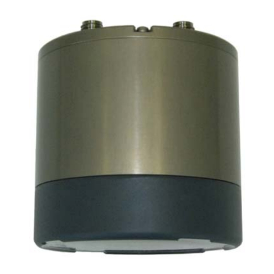
SCIENTIFIC ECHO SOUNDER with DATA LOGGER
APPLICATIONS:
•
Seaglider Installation
•
ROV, AUV & UUV
•
Offshore Oil & Gas
•
Surveying
•
Scientific Research
•
Fisheries Research
Specifications subject to
change without notice
IMAGENEX MODEL 853
FEATURES:
• Programmable
• High performance
• Low power
• Simple set-up and installation
• Digital telemetry
• 25, 50 or 100 m operation
• Compact size
• Communication format available to user
• USB Data download
www.imagenex.com
853 ES with Data Logger
445-076 JANUARY 2011-REVISED MAY 2017
Copyright © 2011 - 2019
Imagenex Technology Corp.
Advertisement
Table of Contents

Related Manuals for IMAGENEX 853


Summary of Contents for IMAGENEX 853
- Page 1 853 ES with Data Logger 445-076 JANUARY 2011-REVISED MAY 2017 IMAGENEX MODEL 853 SCIENTIFIC ECHO SOUNDER with DATA LOGGER APPLICATIONS: FEATURES: • • Programmable Seaglider Installation • • High performance ROV, AUV & UUV • • Low power Offshore Oil & Gas •...
-
Page 2: Hardware Specifications
Stand Alone (one ping per second) 25 m, 50 m, 100 m RANGE SCALES (filename).853 FILE FORMAT 2 GHz Pentium RECOMMENDED 256 MB RAM MINIMUM COMPUT 20 GB Hard Di REQUIREMENTS: 1024 x 768 screen resolution 853 ES with Data Logger 445-076 www.imagenex.com... -
Page 3: Ordering Information
ORDERING INFORMATION: Standard 853-000-140 1000 m UNIT 300 kHz Option -049 Product and company names listed are trademarks or trade names of their respective companies. 853 ES with Data Logger 445-076 www.imagenex.com... - Page 4 Parity, 8 Data Bits and 1 Stop Bit (other baud rates are available). When the Switch Data command is accepted, the 853 responds with a 256 byte IKX Return Data packet or an 18 byte ILX Return Data packet. A message type of IKX must be selected to change any of the programmable settings.
-
Page 5: Operation
65536. New for version 1.02: 853 Echo Sounders are now available with the standard frequency of 120kHz or with an optional frequency of 300kHz. Byte 11 of the 'IKX' Echo Sounder Return Data packet reflects the configured frequency (0=120kHz, 1=300kHz). - Page 6 A timestamp has been added to the ping header. The date and time must be sent to the unit using the appropriate fields in the Switch Data Command. The 853 will keep track of the time until the next command. Each ping header in the file will contain a unique time.
- Page 7 16JUL15 SWITCH DATA COMMAND The 853 accepts up to 27 bytes of switch data from the serial interface and must see the switch data header (2 bytes: 0xFE and 0x44 HEX) in order to process the switches. The unit will stop accepting switch data when it sees the termination byte (0xFD HEX). The termination byte must be present to process the switches.
- Page 8 Dive Type Dive Number (T = 0 or 1) (1 to 32767) Dive Type (T): 0 = A = Descent 1 = B = Ascent Dive Number (nnnnn): 1 to 32767 Model 853 Serial Interface Specification Page 5 of 13...
- Page 9 Byte 10 = (Dive Number & 0x003F80)>>7 Byte 11 = Dive Number & 0x00007F Bytes 12 through 20 contain the interrogation timestamp. The 853 will add the 'ping' time offset to this timestamp as well as automatically increment the time by 1 or 4 seconds each ping depending on the mode (Stand Alone or Glider).
- Page 10 Do not use a value of 253! Byte 25 Reserved Always 0 Byte 26 Termination Byte The echo sounder will stop looking for Switch Data when it sees this byte. Always 0xFD (253 decimal) Model 853 Serial Interface Specification Page 7 of 13...
-
Page 11: Return Data
16JUL15 RETURN DATA After a Switch Data Command, the 853 replies with a serial return data packet. The packet size depends on the value of “Message Type” (Byte 8 of the Switch Data Command). The standard return (Message Type = 0) is a 256 byte “IKX” packet consisting of a 55 byte header, 200 range bins of echo data and a termination byte value of 0xFC. - Page 12 [(Byte 7 & 0x7F)<<7] | (Byte 8 & 0x7F) Byte 9 Range 0 = 25 Meters 1 = 50 Meters 2 = 100 Meters Byte 10 Gain 1 = 20dB 2 = 40dB Model 853 Serial Interface Specification Page 9 of 13...
- Page 13 Dive Number = [(Byte 19 & 0x03)<<14] | [(Byte 20 & 0x7F)<<7] | (Byte 21 & 0x7F) Bytes 22 through 30 contain the current ping timestamp: Byte 22 1 to 31 Model 853 Serial Interface Specification Page 10 of 13...
- Page 14 Milliseconds = [(Byte 29 & 0x7F)<<7] | (Byte 30 & 0x7F) Byte 31-54 Reserved Always 0 Byte 55-254 Logarithmic Echo Data 200 range bins signal level = 10 ^ -(range bin value/20) volts peak-peak Byte 255 Termination Byte 0xFC Model 853 Serial Interface Specification Page 11 of 13...
- Page 15 Bit 1 - 0 Bit 2 - 0 Bit 3 - 0 Bit 4 - 0 Bit 5 - 0 Bit 6 - 1 = Switches Accepted Bit 7 - 1 = Character Overrun Model 853 Serial Interface Specification Page 12 of 13...
- Page 16 [(Byte 7 & 0x7F)<<7] | (Byte 8 & 0x7F) Byte 9-16 Logarithmic Echo Data 8 range bins signal level = 10 ^ -(range bin value/20) volts peak-peak Byte 17 Termination Byte 0xFC Model 853 Serial Interface Specification Page 13 of 13...
-
Page 17: Routine Maintenance
Logger and its' operating environmental specifications including depth and temperature. General Care and Usage Model 853 Echo Sounders are designed to be operated in many types of operating environments. However to prolong the life of the equipment, simple maintenance is required. - Page 18 Operational Environmental Specification While the Model 853 is designed to operate in a wide variety of environments, there are limitations. Table 1 - Model 853 (853-000-140) Environmental Specification Minimum Maximum Units C...
- Page 19 TX232 TX232 TX232 GRN / WHT RX232 RX232 RX232 ORG / WHT USB Data Cable Data - Data + IMAGENEX TECHNOLOGY CORP. 853 Echo Sounder Cable Drawing Title: USB Type 'A' IE55-1204-CCP 853-200-283 Document Number: Date: Sheet March 20, 2012...
Need help?
Do you have a question about the 853 and is the answer not in the manual?
Questions and answers