
Related Manuals for Friendess FSCUT1000S

Summary of Contents for Friendess FSCUT1000S
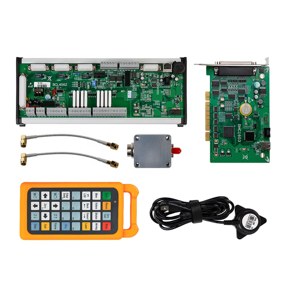
- Page 1 FSCUT1000S Laser Cutting Control System User Manual Shanghai Friendess Electronic Technology Corporation.,Ltd. www.fscut.com Ver 1.1...
- Page 2 FSCUT1000S Laser Cutting Control System User Manual Thank you for choosing our products! This manual gives a detailed introduction to the usage of FSCUT1000S laser cutting controller, including technical features, installation instructions, etc. For CypOne laser cutting software operation, please refer to the Help documentation in the software.
-
Page 3: Table Of Contents
FSCUT1000S Laser Cutting Control System User Manual Contents 第一章 Product introduction......................6 1.1 Brief introduction........................6 1.2 System Connection Diagram....................6 1.3 Technical Reference......................8 1.4 Control Card Installation....................8 1.4.1 Install Steps........................8 1.4.2 Troubleshooting......................9 第二章 Wiring instructions......................11 2.1 Interface description......................11 2.1.1 Interface layout......................11 2.1.2 Power interface specification...................11... - Page 4 FSCUT1000S Laser Cutting Control System User Manual 3.8 Focus control........................58 3.9 Alarm setting........................59 3.9.1 Warning........................59 3.9.2 Emergency stop button:................... 59 3.9.3 Custom alarm:......................59 3.10 General input port......................60 3.11 General output port......................61 3.11.1 Output port:......................61 3.11.2 Auto lubricate......................61 3.11.3 Custom output......................
- Page 5 FSCUT1000S Laser Cutting Control System User Manual 5.1.12 Following deviation is too large................74 5.1.13 Use period has expired...................74 5.1.14 Move close to board....................74 5.1.15 Network Alarm...................... 74 5.2 Analysis of common problems..................75 5.2.1 There is obvious shaking and mechanical impact when Z axis in following movement........................75...
-
Page 6: 第一章 Product Introduction
FSCUT1000S Laser Cutting Control System User Manual 1.1 Brief introduction FSCUT1000S is an open loop laser cutting control system of high performance developed by Shanghai Friendess Company. It is widely used in the field of metal and non-metal laser cutting area which has gained widespread popularity among the vast number of customers. - Page 7 FSCUT1000S Laser Cutting Control System User Manual card BMC1603 connected with IO terminal board BCL4562 by a C62-2 cable; Wiring diagram shown below:...
-
Page 8: Technical Reference
FSCUT1000S Laser Cutting Control System User Manual 1.3 Technical Reference 3 servo axis ports with high frequency pulse output of Motor 2MHz, 1 servo axis with analog output Motion Control 3 servo axis ports with encoder feedback channel, Control Signal quadruple frequency can reach to 8MHz Positive&... -
Page 9: Troubleshooting
FSCUT1000S Laser Cutting Control System User Manual that the card is not inserted properly, please repeat the first step. (3) Install CypOne software. BMC1603 card driver and dongle driver will be installed automatically in CypOne installation. (4) Turn off antivirus software during installation to prevent CypOne identified as virus and installation failed. - Page 10 FSCUT1000S Laser Cutting Control System User Manual (3) If the first half of the "hardware ID" shows:" "means computer recognize the card properly, software installation might fail. Please re-install CypOne software. If it still fails, please contact our technicians. (4) The first half of the "Hardware ID" does not shown as:"...
-
Page 11: 第二章 Wiring Instructions
FSCUT1000S Laser Cutting Control System User Manual 2.1 Interface description 2.1.1 Interface layout BMC1603 card compatible with BCL4562 IO terminal board. The detailed signal port layout as shown below: BCL4562 terminal board uses guide rail or fixed install form. The old version dimension is 315 mm*120 mm*54 mm and the new version dimension is 315 mm*127.8*60 mm. -
Page 12: Servo Control Port
FSCUT1000S Laser Cutting Control System User Manual of the power interface must be reliably connected to the outer shell of the machine. The outer shell of the preamplifier must also be well connected to the outer shell of the machine. The specific index is DC impedance less than 4 ohms, otherwise the actual follow up performance may be poor. - Page 13 FSCUT1000S Laser Cutting Control System User Manual 7 Green-black CLR (Alarm 15 Brown-black 0V (Power clear) ground) 8 Brown 24V (power output) +24V、0V: Supply 24VDC power for servo driver. SON: Servo ON, output servo drive enabling signal; ALM: Alarm, receiving servo driver alarm signal;...
- Page 14 FSCUT1000S Laser Cutting Control System User Manual Fuji ALPHA5 SMART PLUS High Frequency Pulse Parameter Recommended Description Setting Control mode must select position mode. Select command pulse/direction, 500kHZ-4.0MHZ. Motor rotation direction Number of command input pulses per revolution Number of output pulses per revolution...
- Page 15 FSCUT1000S Laser Cutting Control System User Manual Fuji ALPHA5 SMART Series Wiring Diagram Fuji ALPHA 5 Series Parameter Recommended Description Setting PA-101 Position control mode PA-103 Pulse + Direction highest frequency 1 Mpps...
- Page 16 FSCUT1000S Laser Cutting Control System User Manual Panasonic A5 High Frequency Pulse Wiring Diagram Panasonic A5 Low Frequency Pulse Wiring Diagram...
- Page 17 FSCUT1000S Laser Cutting Control System User Manual Panasonic A5 Series basic setting Parameter Recommended Description Setting Pr001 Control mode must select position mode. Pr007 Must select "Pulse + Direction" mode Pr005 When using high speed pulse wiring mode, the parameter setting is 1, and highest pulse frequency.
- Page 18 FSCUT1000S Laser Cutting Control System User Manual Yaskawa Σ series basic setting Parameter Recommended Description Setting Pn000 001X Set position mode Pn00B The setting is 0100 when use single phase power input Pn200 2000H Positive logic: Pulse + direction;0005H negative logic: Pulse + direction...
- Page 19 FSCUT1000S Laser Cutting Control System User Manual Mitsubishi E Series wiring diagram Mitsubishi MR-J3-A series basic setting Parameter Recommended Description Setting PA01 Control mode- Position mode PA13 0011 Negative logic: Pulse + Direction For Mitsubishi J3 series highest pulse frequency is 1Mpps.
- Page 20 FSCUT1000S Laser Cutting Control System User Manual Delta A Series High Frequency Pulse Wiring Diagram Delta ASD-A series basic setting Parameter Recommended Description Setting P1-00 1102H Position control mode, negative logic pulse + direction. Setting is 1102H unlocks high speed differential signal mode, the highest pulse frequency can reach to 4Mpps;...
- Page 21 FSCUT1000S Laser Cutting Control System User Manual Delta B Series High Frequency Pulse Wiring Diagram Parameter Recommended Description Setting 1102H P1-00 Position control mode, negative logic pulse + direction. Setting is 1102H unlocks high speed differential signal mode, the highest pulse frequency can reach to 4Mpps;...
- Page 22 FSCUT1000S Laser Cutting Control System User Manual Sanyo R Series Servo Wiring Diagram Sanyo R Series Basic Setting Parameter Recommended Description Setting SY08 Set position mode Gr8.11 Select pulse signal type: Pulse + direction; Gr9.00 Forward run allowed Gr9.01 Reverse run allowed...
- Page 23 FSCUT1000S Laser Cutting Control System User Manual Schneider 23D High Frequency Pulse Wiring Diagram Schneider Lexium 23D Series Basic Setting Parameter Recommended Description Setting P1-00 1102H Position control mode, negative logic pulse + direction. Setting is 1102H unlocks high speed differential signal mode, the highest pulse frequency can reach to 4Mpps;...
- Page 24 FSCUT1000S Laser Cutting Control System User Manual motion function cannot ensure the control accuracy. To optimize motion effect, please adjust rigidity, gain, Inertia ratio and other parameters. Servo control terminal and PIN description on BCL4562 as shown below: Signal pin description of C15-1.5 cable shown as below:...
- Page 25 FSCUT1000S Laser Cutting Control System User Manual ALM: Receive servo driver alarm signal. A+、A-、B+、B-、Z+、Z-: Encoder three-phase, input signal. Precautions when connecting the driver: (1) Make sure the servo supports velocity control mode. For example, Panasonic A5 series servo must choose full-function type, not pulse type.
- Page 26 FSCUT1000S Laser Cutting Control System User Manual Motor rotate direction 2500 Number of output pulses per revolution Auto tuning gain Zero clamp Speed command scale matches with 500r/v/min in BCS100 controller Brake timing Panasonic servo wiring diagram Panasonic A5 servo parameter set...
- Page 27 FSCUT1000S Laser Cutting Control System User Manual Pr003 Servo stiffness, recommended range 14-20. Pr302 Input gain of speed command Pr315 Enable speed zero-clamp function Pr504 Setup of over-travel inhibition input Panasonic A4 series servo parameter setup Parameter Recommended Description Setting Pr02 Control mode must be velocity mode.
- Page 28 FSCUT1000S Laser Cutting Control System User Manual Yaskawa servo wiring diagram Yaswaka Σ-V series servo parameter setup Parameter Recommended Description Setting Pn000 00A0 Speed control mode with zero-clamp function Pn00B Null The setting is 0100 when use single phase power input...
- Page 29 FSCUT1000S Laser Cutting Control System User Manual Delta A Series servo wiring diagram Delta ASD-A series servo parameter setup Parameter Recommended Description Setting P1-01 0002 Control mode must select velocity control mode. P1-38 2000 Set the largest value of zero-clamp...
- Page 30 FSCUT1000S Laser Cutting Control System User Manual Delta B series servo wiring diagram Parameter Recommended Description Setting P1-01 0002 Control mode must select velocity control mode. P1-38 2000 Set the max value P1-40 5000 Match the parameter speed gain 500 r/min/v in BCS100.
- Page 31 FSCUT1000S Laser Cutting Control System User Manual TECO servo wiring diagram TECO JSDEP Servo parameter setup Parameter Recommended Description Setting Cn001 Control mode must select velocity control mode. Cn002.2 Auto-tuning gain (Note: This is parameter no. 2 of Cn002.) Cn005...
- Page 32 FSCUT1000S Laser Cutting Control System User Manual Mitsubishi servo MR-J30A wiring diagram Mitsubishi MR-J30A Series Parameter Recommended Description Setting PA01 Control mode is speed mode PA15 10000 Number of encoder pulses per revolution x PC12 5000 Corresponding to the speed gain in BCS100 500r/v/min.
- Page 33 FSCUT1000S Laser Cutting Control System User Manual Schneider Servo Lexium 23D Wiring Diagram Schneider Lexium 23D servo parameter setup Parameter Recommended Description Setting P2-10 Set IN1 as SON in servo P2-11 IN2 invalid P2-12 Servo IN3 set as zero speed signal.
- Page 34 FSCUT1000S Laser Cutting Control System User Manual Sanyo R Series Wiring Diagram Sanyo R Series Servo parameter setup Parameter Recommended Description Setting SY08 Velocity control mode Gr0.00 Self-tuning Gr8.25 5000 Maximum speed (r/min) of motor correspond to 10V analog output.
-
Page 35: Limit Signal
FSCUT1000S Laser Cutting Control System User Manual 2.1.4 Limit signal X-: X - Limit, dedicated input port, low level effective; X+: X+ Limit, dedicated input port, low level effective; Y-: Y- Limit, dedicated input port, low level effective; Y+: Y+ Limit, dedicated input port, low level effective;... -
Page 36: General Input Port
FSCUT1000S Laser Cutting Control System User Manual 2.1.5 General input port There are 6 inputs from IN1~IN6.You can assign the 6 inputs as customized button or alarm in config tool. See details in chapter 4 configuration tool. The typical wiring diagram of contact switch as shown below. -
Page 37: Analog Output
FSCUT1000S Laser Cutting Control System User Manual 2.1.7 Analog output There are two 0~10V analog relay outputs in BCL4562.You can set DA1 and DA2 for controlling laser peak power and proportional valve in config tool. Output range 0V~+10V Maximum load... -
Page 38: Wiring Diagram
FSCUT1000S Laser Cutting Control System User Manual 2.2 Wiring diagram... -
Page 39: Laser Wiring Diagram
FSCUT1000S Laser Cutting Control System User Manual 2.3 Laser wiring diagram 2.3.1 Max Laser Wiring Diagram Notice: 1. PD+, PD- is laser alarm output, connect to any input port in BCL4562 and set a customized laser alarm in "Config tool-- alarm--customized alarm”;... -
Page 40: Maxs Series Wiring Diagram
FSCUT1000S Laser Cutting Control System User Manual 2.3.2 Maxs Series Wiring Diagram Note: PWM select 24V control (P1ON, P2 OFF) -
Page 41: Ipg-Ylr Series Wiring Diagram
FSCUT1000S Laser Cutting Control System User Manual 2.3.3 IPG-YLR series wiring diagram We recommend you choose RS232 or network control if laser supports this communication mode, which can control laser realize the function including laser emission, turn on/off guide beam, set peak power, etc., and no need to control peak power by analog DA port. -
Page 42: Raycus Fiber Laser Wiring Diagram
FSCUT1000S Laser Cutting Control System User Manual 2.3.4 Raycus Fiber Laser wiring diagram Note: 1. RayCus's latest products use 24V PWM, the old version use 5V PWM. the key switch to REM then RS232 is available, while the old version switch to ON. -
Page 43: Wiring Precautions
FSCUT1000S Laser Cutting Control System User Manual Note: Part of CO2 laser also supports PWM control mode, wiring can take reference from Max laser. 2.4 Wiring precautions 2.4.1 Specification for cable layout 1. When releasing the cable from the coil, it is necessary to prevent the cable from twisting (it needs to be laid along the tangent direction) and to straighten the cable. - Page 44 FSCUT1000S Laser Cutting Control System User Manual Correct example Error example 2. The cable is not allowed to twist when it is installed in enclosed space. The twist during installation may lead to premature damage of the core strand. This effect is gradually strengthened in the operation of the cable, resulting in the phenomenon of back-twisting, which eventually leads to core breakage and failure.
- Page 45 FSCUT1000S Laser Cutting Control System User Manual fixed points. It is necessary to use the appropriate cable support provided by the towing chain supplier. When operating at high acceleration, the applicability of cable strapping is very limited. It should be prevented to tie multiple cables together.
-
Page 46: Specification For Machine Tool Wiring
FSCUT1000S Laser Cutting Control System User Manual fixed point until it runs smoothly. 10. In view of the absolute size of cables and towing chains, their length variation characteristics are quite different. In the first few hours of operation, the cable stretched naturally. - Page 47 FSCUT1000S Laser Cutting Control System User Manual (1) The ground wire adopts standard yellow green double color line. (2) There are some high frequency signals (PWM, pulse, encoder, capacitance signal, etc.) in the laser cutting machine tool. It is suggested to use multi-point grounding.
-
Page 48: Product Assembly Requirements
FSCUT1000S Laser Cutting Control System User Manual (3) When choosing Friendess wires, choose the appropriate type of wire according to the layout space, do not accumulate hovering. (4) All wiring must be reliable and not loose to prevent ignition. (5) Wiring avoids formation of loops and prevents antenna effects. A current loop consisting of a signal source, a transmission line, a load is equivalent to a magnetic field antenna. - Page 49 FSCUT1000S Laser Cutting Control System User Manual Except the USB interface, the other interfaces are not allowed to plug, and the plug may cause the internal components to burn down. Please take it carefully, forbid external pressure to press the card.
-
Page 50: 第三章 Platform Configuration T
FSCUT1000S Laser Cutting Control System User Manual 3.1 Installation Configuration tool will be installed automatically in CypOne software installation. Click "start" menu- "All programs"-"CypOne laser cutting system"-"Config tool" to startup config tool . "CypOne laser cutting system" is software name, which differs from different OEM software version. -
Page 51: User Interface
FSCUT1000S Laser Cutting Control System User Manual 3.3 User interface The main page of config tool is machine structure. Click the icon at top bar to enter different parameter model. You can config signal assignment of limit switch, laser, gas etc. You can click "config file" locate to Data file folder. -
Page 52: Machine Mechanism Config
FSCUT1000S Laser Cutting Control System User Manual Machine mechanism config Select single drive or dual by the actual X/Y axis structure. The travel range of X axis: The maximum travel range of X axis when use software limit function, and define the width of the white square in CypOne main page. -
Page 53: Return Origin Configuration
FSCUT1000S Laser Cutting Control System User Manual 3.5 Return origin configuration Soft Limit: Enable this function will force open the soft limit function, users can't turn off on CypOne software. Prompt go origin at start: Display go origin message in main page to remind user. -
Page 54: Laser Configuration
FSCUT1000S Laser Cutting Control System User Manual 3.6 Laser configuration CypOne provides configuration parameter for Max laser, Mars, IPG, RayCus, Valley Nuo and other type, each laser type has corresponding configuration parameter. 3.6.1 Max Laser Configuration Guide beam output: Set output to control guide beam. -
Page 55: Ipg Laser Configuration
FSCUT1000S Laser Cutting Control System User Manual 3.6.3 IPG Laser configuration Guide beam output: Set output to control guide beam. DA port selection: There are 2 analog DA ports on BCL4562 terminal board, choose either of them to control laser peak power. When use RS232 or network control doesn't require DA port. -
Page 56: Valley Nuo Laser Configuration
FSCUT1000S Laser Cutting Control System User Manual either of them to control laser power. DA voltage range: The analog signal voltage range to control laser power. RayCus laser supports serial communication. 3.6.5 Valley Nuo Laser Configuration Mechanical emission gate: Output port to control mechanical emission gate. -
Page 57: Gas Configuration
FSCUT1000S Laser Cutting Control System User Manual 3.7 Gas configuration Valve: Output to turn on/off cutting gas. Air: Output to turn on/off air Oxygen: Output to turn on/off oxygen Nitrogen: Output to turn on/off nitrogen DA Gas Control: An output port to control proportional valve... -
Page 58: Focus Control
FSCUT1000S Laser Cutting Control System User Manual 3.8 Focus control Focus control function must be realized by BCL4516E terminal board. Connect in the BCL4516E in config tool-extend IO. Focus range: Set software limit and travel range. Focus position at org position: The focus scale at origin position Pulse rate: Command pulses send to servo correspond with focus moving distance. -
Page 59: Alarm Setting
FSCUT1000S Laser Cutting Control System User Manual 3.9 Alarm setting 3.9.1 Warning Display the warning message of yellow color when machine is running. You can edit the warning message. 3.9.2 Emergency stop button: Assign the input port and signal logic of emergency button. Controller will send emergency stop alarm once the input signal is valid. -
Page 60: General Input Port
FSCUT1000S Laser Cutting Control System User Manual 3.10 General input port Click function button you can select port number and set signal logic. The signal port can't be reapplied. -
Page 61: General Output Port
FSCUT1000S Laser Cutting Control System User Manual 3.11 General output port 3.11.1 Output port: Lasering: If this port configured, the indicator will light when laser is firing. Working: If this port configured, the indicator will light when machine in cutting process. -
Page 62: Regional Output
FSCUT1000S Laser Cutting Control System User Manual 3.11.4 Regional output Regional output is used for dust collection. When laser is firing, the output in the region where laser head is in will open. If laser head move from region 1 to region 3, then output in region 1 close and output in region 3 open. -
Page 63: Velocity Parameter
FSCUT1000S Laser Cutting Control System User Manual 3.12.1 Velocity parameter The parameter description shown in below list: Parameter Description name The follower move down and lift up speed. Recommended to Moving speed setup a value when motor maintain a rated rotating speed to guarantee the efficiency and stable operation. -
Page 64: Reset Parameter
FSCUT1000S Laser Cutting Control System User Manual When finish cutting, laser head will lift up and park at this Dock position position. The travel range of the Z axis. If soft limit enabled, once Z Z range axis exceed this range will stop immediately and send alarm "exceed Z range"... - Page 65 FSCUT1000S Laser Cutting Control System User Manual Pulses per Pulses feedback every revolution. This parameter must be revolution same with the value in servo. Support Panasonic/Mitsubishi, Yaskawa/Delta, Teco JSDEP these three types servo. The zero-clamp signal logic, input and Servo type output logic as well as related parameters in controller are different with different types of servo.
-
Page 66: 第四章 Machine Debug And Tuning
FSCUT1000S Laser Cutting Control System User Manual 4.1 Input and output signal test After finish the wiring of electric circuit, you can start machine debug and tuning: (1) Connect terminal board and control card with C62-2 cable, and supply 24V power to terminal board. -
Page 67: Calculate Inertia Ratio And Machine Performance Features
FSCUT1000S Laser Cutting Control System User Manual (3) Close monitor page enter in CypOne main interface. At the right side in control panel manual jog Z axis up and down, press gas, laser and aiming beam, set laser power to text the machine function. -
Page 68: Servo Gain Adjustment
FSCUT1000S Laser Cutting Control System User Manual Note: Servo parameters calculated by servo only can be used in FSCUT4000. 4.3 Servo gain adjustment 4.3.1 Basic Requirements This required professionals who are experienced with servo tuning tools. PANATERM servo tuning tool for Panasonic servo, SigmaWin+ for Yaskawa servo, experienced with servo tool can simplify the process. -
Page 69: Delta Servo Adjustment
FSCUT1000S Laser Cutting Control System User Manual Pn401 -correspond with Panasonic Pr104 The table as below please notice the unit and decimal point. The unit of Pn101 parameter in Yaskawa is 0.01ms, while in Panasonic Pr102 unit is 0.1ms. -
Page 70: Adjust Cutting Acceleration
FSCUT1000S Laser Cutting Control System User Manual acceleration ACC/DEC in corner motion, which adjusted by torque curve in servo tool. Work Smaller value will improve the vibration suppression but extend the frequency ACC/DEC time. Curve Larger value will smooth the curve and improve the speed but also precision reduce the precision. -
Page 71: Curve Precision And Corner Precision
FSCUT1000S Laser Cutting Control System User Manual Increase the low pass filter as much as possible without affecting the cutting precision. The reference standard of test cutting is no waves around the corner in rectangular, star type cutting. You can setup as the experiential value in below table. -
Page 72: 第五章 Faq
FSCUT1000S Laser Cutting Control System User Manual 5.1 System alarm and analysis 5.1.1 Z axis limit enabled Limit sensor being triggered will send this alarm. Under this case check the items below: Check the wiring. Check if the "Limit logic" correctly set as "normally open" or "normally closed". -
Page 73: Encoder Has No Response
FSCUT1000S Laser Cutting Control System User Manual Axis shaking caused by external force. Signal pin terminal not fixed and zero speed clamp signal is invalid. Servo rigidity is too weak. There is interference to the encoder cable. Check if the cable well ground and add ceramic ring. -
Page 74: Capacitance Abnormally Became Larger
FSCUT1000S Laser Cutting Control System User Manual smaller than 15mm), might cause the alarm. Bad contact in nozzle and amplifier cable. The plasma cloud impact. Plasma cloud often formed in cutting stainless steel especially with film. For stainless steel with film, it should defilm then cut, do not cut with film. - Page 75 FSCUT1000S Laser Cutting Control System User Manual Instruction CypOne send wrong instruction ID. error 5.2 Analysis of common problems 5.2.1 There is obvious shaking and mechanical impact when Z axis in following movement. Bad contact between amplifier shell/controller FG pin with machine frame.
- Page 76 FSCUT1000S Laser Cutting Control System User Manual No preheating Please preheat 2-5 minutes and wait for the sampling capacitance stable before further operations. Ceramic nut not tightened Ceramic nut not tightened may lead to unstable capacitance. 5.2.3 Following distance different with the actual setting ...
Need help?
Do you have a question about the FSCUT1000S and is the answer not in the manual?
Questions and answers