
Related Manuals for Knick Ceramat WA 154


Summary of Contents for Knick Ceramat WA 154
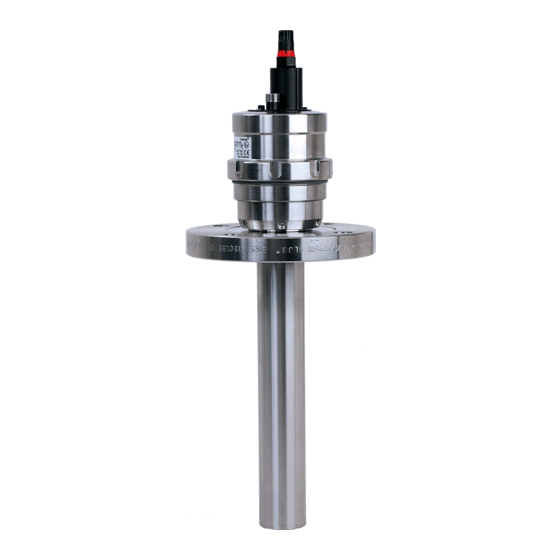
- Page 1 Ceramat WA 154 User Manual Sensor Lock-Gate English Latest Product Information: www.knick.de...
-
Page 2: Safety Information
NOTICE Process-related risks Knick Elektronische Messgeräte GmbH & Co. KG assumes no liability for damages caused by process-related risks known to the operator, which would in fact not permit the use of the sensor lock-gate. Please note:... - Page 3 Exceeding the standard atmospheric conditions within the manufacturer’s specifications, such as ambient tem- perature, process pressure and temperature, does not impair the durability of the retractable fittings. Related certificates are included in the product’s scope of delivery and are available at www.knick.de in the cur- rent version.
-
Page 4: Table Of Contents
Table of Contents Safety Information .........................2 Table of Contents ..........................4 Intended Use ...........................5 Rating Plates ................................6 Package Contents ...........................7 Product Coding ..........................8 Function Description ........................10 Composition of the Sensor Lock-Gate ..................11 Information on Installation ......................13 Connection to Unical or Uniclean ....................17 Installing/Removing a Sensor .....................18 pH Sensors .................................19 Sensor Dismount Guard ............................19... -
Page 5: Intended Use
Intended Use The Ceramat pneumatic sensor lock-gate with ceramic sealing is used for installing a sensor for measuring process variables in liquid media. The sensor can be cleaned, calibrated, or replaced under process conditions (pressure and temperature). Since the pneumatic drive unit and the process unit with the ceramic sensor lock-gate are separate modules, the drive unit can be removed and replaced under process conditions. -
Page 6: Rating Plates
Intended Use Rating Plates Ceramat WA 15x-N Drive ® Ceramat Retractable Fitting / Drive Unit Type Max. pressure Temperature range 14163 Berlin Made in Germany Process Ceramat ® Max. pressure Retractable Fitting/Process Unit Temperature range Type 14163 Berlin Made in Germany Ceramat WA 15x-X Drive KEMA 04 ATEX 4035X... -
Page 7: Package Contents
Package Contents Check the shipment for transport damage and completeness. The package should contain: • Sensor lock-gate • Documentation • Test certificates... -
Page 8: Product Coding
Product Coding WA 154 - – Explosion protection ATEX Zone 0 Without Sensor Sensor, Ø 12 mm, with PG 13.5 pH sensor, Ø 12 mm, pressurized Optical sensor, Ø 1/2” (12.7 mm) Optical sensor, Ø 12 mm Material of gaskets EPDM EPDM - FDA FKM - FDA... - Page 9 Product Coding WA 154 - – Dairy pipe DN 50 Dairy pipe DN 65 Dairy pipe DN 80 Dairy pipe DN 100 Flange, loose, ANSI 316,150 lbs, 2” Flange, loose, ANSI 316, 150 lbs, 2 1/2” Flange, loose, ANSI 316, 150 lbs, 3” Flange, loose, ANSI 316, 150 lbs, 3.5”...
-
Page 10: Function Description
Function Description The pneumatically operated sensor lock-gate allows calibrating or adjusting the measuring system and clean- ing the sensor in the running process. For that purpose, the sensor can be moved between two positions: PROCESS position: The sensor is located in the process medium. SERVICE position: The sensor is located in the calibration chamber. -
Page 11: Composition Of The Sensor Lock-Gate
Composition of the Sensor Lock-Gate The Ceramat sensor lock-gate consists of 2 main units: drive unit and process unit. The drive unit performs the movements required to open and close the ceramic rotary slide and to move the sensor into and out of the process. The process unit comprises the ceramic sensor lock-gate with calibration chamber in the probe hous- ing as well as the process adaptation (eg,, flange or dairy-pipe screw joint). - Page 12 Composition of the Sensor Lock-Gate Drive Units Drive Units For sensors with For sensors with solid electrolyte liquid electrolyte Process Adadaption (Example) Flange...
-
Page 13: Information On Installation
Information on Installation For operation of the Ceramat, you must connect control air, rinsing or calibration media, and the electrical˜check-back signal for indicating the probe position. There are two possible ways to do so. When the Ceramat is operated with a Unical or Uniclean electro-pneumatic controller and the Protos measur- ing system, the cables and tubings for air pressure, rinsing/calibration media and check-back are combined in a single hose with just one plug connection (multiplug). - Page 14 Information on Installation Installing the outlet hose Do not install the outlet hose more than 1 meter below calibration chamber level (see figure 2). Doing so raises the danger of air being sucked out of the calibration chamber due to the drop in pressure. Leakage of the calibration chamber due to gravity alone is prevented by the loop in the outlet hose when the Ceramat is installed at an angle of up to 15°...
- Page 15 Information on Installation Connecting the outlet hose Turn the outflow nipple so that the outlet hose points outwards (see figure on the left). Before tightening the coupling nut, correctly align and insert the outflow nipple! NOTICE Check positioning of coding recesses and coding bars to lock the connection.
- Page 16 Information on Installation The following procedure is recommended for installing the media connection (also applies to installation of ZU 0631 standard-media interface): Attaching the hose to the fixing bracket of the Ceramat Attach the bracket of the media connection to the fixing bracket of the Ceramat with mounting screws.
-
Page 17: Connection To Unical Or Uniclean
Connection to Unical or Uniclean The media connection is available in 5 m, 10 m, 14 m, or 17 m length (other lengths on request). It consists of a Ø 30 mm corrugated hose with a metal coil. You can also order special lengths (also heated or with wall ducts). 2 variants are available: •... -
Page 18: Installing/Removing A Sensor
Installing/Removing a Sensor NOTICE Sensors must only be installed or removed by trained personnel authorized by the operating company. The Ceramat sensor lock-gate must be in SERVICE position. This position is attained by: • the “Maintenance” menu when controlled by Protos 3400(X) (see user manual of PHU 3400(X)-110 module) •... -
Page 19: Ph Sensors
Installing/Removing a Sensor pH Sensors Be sure to follow the assembly instructions step by step. Preparations: • Check whether the sensor is damaged (glass broken?). Never install a damaged sensor. • Check whether slide washer or O-ring on the sensor are damaged and replace if required. •... -
Page 20: Installing/Removing A Solid-Electrolyte Sensor
3) Loosen the sensor plug. 4) Loosen the sensor using a suitable tool and pull it out. Be sure not to cant the sensor because it might break (recommended tool for removing the sensor: 19 mm A/F, eg, Knick ZU˜0647 wrench). -
Page 21: Installing/Removing A Liquid-Electrolyte Sensor
Installing/Removing a Liquid-Electrolyte Sensor pH Sensors You can use sensors with a length of 450 mm and an electrode diameter of 12 mm. To ensure that the electrolyte flows from the reference electrode to the process medium, the air pressure in the sensor pressure chamber must be 0.5 to 1 bar above that of the process medium. - Page 22 Installing/Removing a Liquid-Electrolyte Sensor Installing or removing the sensor 1) Only install or remove the sensor when the sensor lock-gate is in SERVICE position. 2) Loosen small coupling nut (A) – do not remove it. 3) Unscrew large coupling nut (B) completely (counterclockwise).
-
Page 23: Cavity Rinsing Function
Cavity Rinsing Function In SERVICE position, inlet and outlet are directly connected with the calibration chamber. The ceramic slides are mounted in an outer housing, which is in contact with the process. There is a risk that process fluid penetrates into the cavity between ceramic and outer housing. Such fluids can be drained off using the cavity rinsing function. -
Page 24: Maintenance Work On The Drive Unit
Maintenance Work on the Drive Unit The drive unit must be removed, for example: • for general maintenance or inspection • to clean the calibration chamber, eg, after a sensor has broken • to change the sensor / calibration-chamber gaskets •... -
Page 25: Removing The Drive Unit
Removing the Drive Unit NOTICE Be sure to follow these instructions in the correct sequence. Take appropriate safety precautions against escaping process fluids. 1) Move probe into SERVICE position. Only in this position can the drive unit be removed. 2) Switch off compressed air and deaerate device! 3) Make sure that no process fluid is leaking from the outlet. -
Page 26: Installing The Drive Unit
Installing the Drive Unit NOTICE Be sure to follow these instructions in the correct sequence. 1) Before installing the drive unit in the process unit, check whether the drive unit is in SERVICE position. Only then can the drive unit be inserted sufficiently deep into the process unit so that the groove can engage with the coupling nut. -
Page 27: Installation Dimensions
Installation Dimensions Solid Electrolyte... -
Page 28: Liquid Electrolyte
Installation Dimensions Liquid Electrolyte... -
Page 29: Immersion Depths (Process Adadaption: Flange)
Installation Dimensions Immersion Depths (Process Adadaption: Flange) * ID = immersion depth... -
Page 30: Specifications
Specifications Permissible process pressure and 10 bar (up to 140 °C) temperature during movement Permissible process pressure and 16 bar (at 0 ... 40 °C) temperature, statically in SERVICE position Ambient temperature -10 ... 70 °C Ingress protection IP 66 Permissible pressure for probe control (4) 5 ... -
Page 31: Maintenance Intervals
Maintenance Intervals Because of the highly variable process conditions (pressure, temperature, chemically aggressive media etc.), general information on necessary maintenance intervals is difficult to provide. If proven experience has been gained from similar points of measurement with regard to materials used and their resistance unter process conditions, the maintenance intervals can be adjusted by the customer. -
Page 32: Lubricants, O-Rings
Lubricants, O-Rings For fittings used in the chemical industry, the lubricant Syntheso Glep1 (silicone-free) is applied. For fittings used in the pharmaceutical / food industry (when FDA conformity is required), the lubricant Beruglide L (silicone-free) is applied (registered according to NSF-H1). On request, the lubricant Paraliq GTE 703 can be applied (excellent lubricating properties also at increased temperatures and for a large number of stroke movements). -
Page 33: Sealing Kits For Maintenance And Servicing
Sealing Kits for Maintenance and Servicing The sealing kits are available in different materials. The new O-rings must be lubricated with the included lubricant. The following sealing kits are available for repair and servicing: Sealing kit Process-wetted / rinse-wetted sealings Order no. -
Page 34: Accessories / Spare Parts
Accessories / Spare Parts Accessories / Spare Parts Order no. Sensor mounting wrench, 19 mm ZU 0647 Air supply for pressurized sensors, 0.5 - 4 bar ZU 0670/1 Air supply for pressurized sensors, 1 - 7 bar ZU 0670/2 Mounting wrench for Ceramat ZU 0648 Pneumatically operated manual control valve ZU 0646... - Page 35 Accessories / Spare Parts ZU 0647 Sensor mounting wrench, 19 mm Required for safely screwing in the sensor without overloading the PG 13.5 plastic thread of the sensor head by an excessive torque (as caused by an open-end wrench). ZU 0648 Mounting wrench for Ceramat Serves to disconnect the drive unit or mount it to the process unit via the...
- Page 36 Accessories / Spare Parts Long sensor socket with mounted O-rings This sensor socket is recommended for brittle incrustations (eg, lime). (Hastelloy C22 material can be identified by a missing grip recess.) • ZU 0672/A Sensor socket 1.4571, O-rings FKM • ZU 0672/B Sensor socket 1.4571, O-rings EPDM •...
- Page 37 Accessories / Spare Parts Sensor socket with mounted O-rings and scraper ring with scraper edge made of PEEK This sensor socket is recommended for sticky media and for particles in the process medium. Please observe the notice on page 19. • ZU 0705 Sensor socket PEEK, O-rings FKM •...
- Page 38 Accessories / Spare Parts Adapter for additional medium This adapter allows the introduction of an additional rinse medium beyond the available media connection (media hose). It is mounted between the Ceramat and the media hose multiplug. The following variants are available: •...
-
Page 39: Declaration Of Contamination
I have answered the above questions to the best of my knowledge. Name: Company: Date: Signature: Knick Elektronische Messgeräte GmbH & Co. KG, Beuckestr. 22, 14163 Berlin, Germany Phone +49 (0) 30 801 91 - 0 / Fax +49 (0) 30 801 91-200 087148 E-mail: knick@knick.de / Internet: www.knick.de... -
Page 40: Index
Index Accessories 34 Liquid-electrolyte sensor, dimensions 28 Adapter for additional medium 38 Lubricants 32 Adjustment 10 Air supply for pressurized sensors, ZU 0670 37 Maintenance, drive unit 24 Ambient temperature 30 Maintenance interval 31 Maintenance, lubricants 32 Calibration 10 Maintenance, operations required 31 Calibration chamber 23 Maintenance, sealing kits 33 Calibration media 13... - Page 41 Index Sensor connection 18 Sensor dismount guard 19 Sensor mounting wrench, ZU 0647 35 Sensor preparation 19 Sensor sockets 35 Sensor with liquid electrolyte 21 Sensor with liquid electrolyte, dimensions 28 Sensor with solid electrolyte 20 Sensor with solid electrolyte, dimensions 27 SERVICE position 10 Servicing, sealing kits 33 Solid-electrolyte sensor, dimensions 27...
- Page 44 Knick Elektronische Messgeräte GmbH & Co. KG Beuckestraße 22 14163 Berlin Phone: +49 30 80191-0 Fax: +49 30 80191-200 Internet: www.knick.de Email: knick@knick.de 097345 TA-203.092-KNEN02 20200622...
Need help?
Do you have a question about the Ceramat WA 154 and is the answer not in the manual?
Questions and answers