MR VACUTAP VR-Ex Installation And Commissioning Instructions
On-load tap-changer
Hide thumbs
Also See for VACUTAP VR-Ex:
- Installation and commissioning instructions (236 pages) ,
- Operating instructions manual (88 pages) ,
- Installation and commissioning instructions (236 pages)

Related Manuals for MR VACUTAP VR-Ex


Summary of Contents for MR VACUTAP VR-Ex
- Page 1 On-load tap-changer ® VACUTAP VR-Ex Installation and commissioning instructions 7545652/00 EN . Irm 700…1 300 A, selector sizes RC/RD/RDE/RE/RF/RES...
- Page 2 © All rights reserved by Maschinenfabrik Reinhausen Dissemination and reproduction of this document and use and disclosure of its content are strictly prohibited unless expressly permitted. Infringements will result in liability for compensation. All rights reserved in the event of the granting of patents, utility models or designs.
-
Page 3: Table Of Contents
Table of contents Table of contents Introduction......................... 7 Manufacturer............................ 7 Completeness............................. 7 Safekeeping............................ 7 Notation conventions .......................... 7 1.4.1 Hazard communication system .......................... 7 1.4.2 Information system.............................. 9 1.4.3 Instruction system .............................. 9 Safety.......................... 11 Appropriate use .......................... 11 Inappropriate use.......................... 12 Fundamental safety instructions ....................... 12 Standards and regulations........................ - Page 4 Table of contents Packaging, transport and storage .................. 35 Packaging ............................ 35 4.1.1 Suitability................................ 35 4.1.2 Markings................................ 36 Transportation, receipt and handling of shipments................ 36 Storage of shipments........................ 37 Unpacking shipments and checking for transportation damages ............. 38 Mounting ........................... 39 Installation information........................ 39 Preparatory work ..........................
- Page 5 Table of contents 5.5.3 Fitting motor-drive unit ............................ 185 5.5.4 Fitting drive shaft............................... 185 5.5.5 Centering on-load tap-changer and motor-drive unit .................. 209 5.5.6 Making the electrical connections for the motor-drive unit ................ 209 Commissioning....................... 210 Commissioning the on-load tap-changer at the transformer manufacturer's site ...... 210 6.1.1 Bleeding on-load tap-changer head and suction pipe.................. 210 6.1.2...
- Page 6 Table of contents Drawings ......................... 234 Dimensional drawings........................ 234 9.1.1 10017720 ................................ 235 9.1.2 10009917 ................................ 236 On-load tap-changer head...................... 237 9.2.1 720847 ................................ 238 9.2.2 720781 ................................ 239 9.2.3 895168 ................................ 240 9.2.4 892916 ................................ 241 9.2.5 890183 ................................ 242 9.2.6 723015 ................................ 243 9.2.7 720845 ................................ 244 9.2.8 766161 ................................ 245 Adjustment plans ..........................
-
Page 7: Introduction
1 Introduction 1 Introduction This technical file contains detailed descriptions of the safe and proper in- stallation, connection, and commissioning of the product. It also includes safety instructions and general information about the prod- uct. Information about operation can be found in the operating instructions. This technical file is intended solely for specially trained and authorized per- sonnel. - Page 8 1 Introduction 1.4.1.1 Warning relating to section Warnings relating to sections refer to entire chapters or sections, sub-sec- tions or several paragraphs within this technical file. Warnings relating to sections use the following format: Type of danger! WARNING Source of the danger and outcome. ►...
-
Page 9: Information System
1 Introduction Pictogram Definition Warning of combustible substances Warning of danger of tipping Warning of danger of crushing Table 2: Pictograms used in warning notices 1.4.2 Information system Information is designed to simplify and improve understanding of particular procedures. In this technical file it is laid out as follows: Important information. - Page 10 1 Introduction Aim of action ü Requirements (optional). 1. Step 1. ð Result of step (optional). 2. Step 2. ð Result of step (optional). ð Result of action (optional). ® VACUTAP VR-Ex 7545652/00 EN Maschinenfabrik Reinhausen GmbH 2020...
-
Page 11: Safety
2 Safety 2 Safety ▪ Read this technical file through to familiarize yourself with the product. ▪ This technical file is a part of the product. ▪ Read and observe the safety instructions provided in this chapter. ▪ Read and observe the warnings in this technical file in order to avoid func- tion-related dangers. -
Page 12: Inappropriate Use
2 Safety In the standard version, the on-load tap-changer is designed for sinusoidal 50/60 Hz alternating current with a curve form symmetrical to the zero axis and can switch 1.5 times the rated through-current I at its rated step voltage Exceeding the rated step voltage U for a short period by up to 10% is per- mitted if the rated through-current I... - Page 13 2 Safety Work area Untidy and poorly lit work areas can lead to accidents. ▪ Keep the work area clean and tidy. ▪ Make sure that the work area is well lit. ▪ Observe the applicable laws for accident prevention in the relevant coun- try.
-
Page 14: Standards And Regulations
2 Safety ▪ It is imperative that you consult with Maschinenfabrik Reinhausen GmbH because specific operating conditions apply to alternative insulating fluids. ▪ Only use conductive and grounded hoses, pipes, and pump equipment that are approved for flammable liquids. ▪ Only use lubricants and auxiliary materials approved by the manufacturer. ▪... - Page 15 2 Safety Equipment groups (number 2) Equipment in this category is intended for use in underground parts of mines as well as those parts of surface installations of such mines endangered by firedamp and/or combustible dust. Equipment in this category is intended for use in other areas in which explosive atmospheres may be present.
-
Page 16: Standards And Regulations
2 Safety Explosion group (number 6) EN/IEC Gases, vapors (examples) Min. ignition energy (mJ) Ammonia Acetic acid, acetone, benzene, diesel, 0.18 ethane, ether, fuel oil, hexane, meth- ane, petrol, petroleum, propane Ethylene, isoprene, town gas 0.06 Acetylene, carbon disulfide, hydrogen 0.02 Table 7: Explosion groups Temperature classes (number 7) -
Page 17: Measures For Ensuring Compliance With Explosion Protection Requirements
2 Safety 2.5 Measures for ensuring compliance with explosion protection requirements 2.5.1 Measures taken by the manufacturer Maschinenfabrik Reinhausen has taken the following measures for ensuring compliance with explosion protection requirements. You do not need to take any special measures in this regard. 2.5.1.1 Quality of the insulating oil in the on-load tap-changer The quality of the insulating oil required by IEC 60296 and the quality of the synthetic esters required by IEC 61099 in the oil compartment of the on-load... - Page 18 2 Safety 2.5.2.2 Setting up the on-load tap-changer oil system Operate the on-load tap-changer only with a suitable oil system. This di- verter switch oil system consists of the diverter switch oil compartment, pro- tective relay, and oil conservator of the on-load tap-changer. It ensures that enough insulating oil is present in the diverter switch oil compartment at all times.
- Page 19 2 Safety 2.5.2.3.1 Dehydrating breather The oil conservator must be equipped with a dehydrating breather in accor- dance with VDE 0532-216-5 with downward-leading outlet and a protection degree of at least IP66 in accordance with IEC 60529. 2.5.2.3.2 Level indicator The oil conservator must have a level indicator from which the minimum oil quantity required and the maximum quantity permitted, as well as the current oil level, can be read.
-
Page 20: Personnel Qualification
2 Safety 2.5.2.4 Corrosion protection measures Because further installation steps are required before operation of the on- load tap-changer, sufficient corrosion protection cannot be provided at cer- tain interfaces to the transformer when the device leaves the factory. Figure 2: On-load tap-changer head 1 Sealing surface on piping connec- 3 Contact surface on on-load tap- tion flange... - Page 21 2 Safety Electrically skilled person The electrically skilled person has a technical qualification and therefore has the required knowledge and experience, and is also conversant with the ap- plicable standards and regulations. The electrically skilled person is also pro- ficient in the following: ▪...
-
Page 22: Personal Protective Equipment
2 Safety 2.7 Personal protective equipment Personal protective equipment must be worn during work to minimize risks to health. ▪ Always wear the personal protective equipment required for the job at hand. ▪ Never wear damaged personal protective equipment. ▪ Observe information about personal protective equipment provided in the work area. -
Page 23: Product Description
3 Product description 3 Product description 3.1 Scope of delivery The product is packaged with protection against moisture and is usually de- livered as follows: ▪ Oil compartment with on-load tap-changer head and built-in diverter switch insert ▪ Selector ▪ Ex motor-drive unit ▪... -
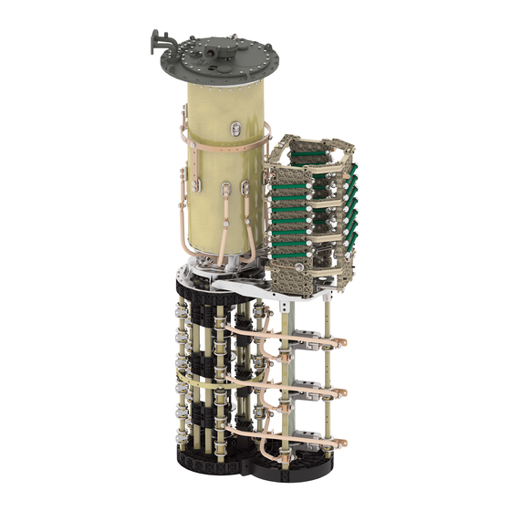
Page 24: Design/Versions
3 Product description Figure 3: System overview of on-load tap-changer, transformer 1 Transformer tank 6 Upper gear unit 2 Motor-drive unit 7 On-load tap-changer 3 Vertical drive shaft 8 Protective relay 4 Bevel gear 9 Oil conservator 5 Horizontal drive shaft 10 Active part of the transformer 3.2.2 Design/versions The following drawing shows the main components of the on-load tap-... - Page 25 3 Product description Figure 4: On-load tap-changer design 1 On-load tap-changer head 2 Upper gear unit 3 Pipe bend 4 Oil compartment 5 Tap selector 6 Change-over selector (optional) 7 On-load tap-changer head cover 8 Rupture disk ® Maschinenfabrik Reinhausen GmbH 2020 7545652/00 EN VACUTAP VR-Ex...
- Page 26 3 Product description 3.2.2.1 Pipe connections The on-load tap-changer head features 4 pipe connections for different pur- poses. Depending on the order, some or all of these pipe connections are fitted with pipe bends ex factory. All pipe bends can be freely swiveled once the pres- sure ring is loosened.
-
Page 27: Nameplate And Serial Number
3 Product description tween the transformer tank and oil compartment of the on-load tap-changer, which is necessary for drying, filling with insulating fluid and transportation of the transformer. 3.2.3 Nameplate and serial number The nameplate with serial number is on the on-load tap-changer head cover. Figure 6: Nameplate The serial number can also be found on the selector. - Page 28 3 Product description 3.2.4.1 Protective relay 3.2.4.1.1 Function description The protective relay is looped into the circuit breaker tripping circuit, thus protecting the on-load tap-changer and transformer in the event of a fault within the on-load tap-changer oil compartment. It is tripped when the speci- fied speed of flow from the on-load tap-changer head to the oil conservator is exceeded due to a fault.
- Page 29 3 Product description Rear view Figure 9: RS 2001-Ex 1 Ground connection 2 Nameplate View from above Figure 10: RS 2001-Ex 1 Gasket 2 Potential tie-in 3 Terminal box cover 4 Slotted head screw for potential tie-in 5 OPERATION (reset) test button 6 Slotted head screw for protective cover 7 OFF (test tripping) test button...
-
Page 30: Drive Shaft
3 Product description 3.2.4.1.3 Name plate The name plate for the explosion-protected protective relay is on the rear of the product. Figure 11: Position of name plate 3.2.4.2 Rupture disk The rupture disk is a pressure relief device without signaling contact in ac- cordance with IEC 60214-1 and is located in the on-load tap-changer head cover. - Page 31 3 Product description The explosion-proof drive shaft consists of a square tube with insulator and is coupled by two coupling brackets and one coupling bolt at both ends to the drive or driven shaft end of the device to be connected. Figure 12: Explosion-proof drive shaft with insulator ®...
-
Page 32: Design/Model
3 Product description 3.3.2 Design/Model The design of the explosion-proof drive shaft is described in this section. Figure 13: Components of the explosion-proof drive shaft 1 Bevel gear 2 Hose clip 3 Screws 4 Telescopic protective tube 5 Coupling bracket 6 Insulator 7 Double coupling bracket 8 Square tube 9 Pin... - Page 33 3 Product description Configuration V 1 min Intermediate bearing Middle of hand crank – middle of 706 mm If the maximum value of bevel gear (maximum permissible 2472 mm is exceeded, the axial offset 2°) use of an intermediate bearing is necessary. V 1 ≤ 2472 mm (without in- termediate bearing) V 1 >...
-
Page 34: Identification Plate
3 Product description 3.3.3 Identification plate The identification plate is on the telescopic protective tube. Figure 14: Position of the identification plate ® VACUTAP VR-Ex 7545652/00 EN Maschinenfabrik Reinhausen GmbH 2020... -
Page 35: Packaging, Transport And Storage
4 Packaging, transport and storage 4 Packaging, transport and storage 4.1 Packaging The products are sometimes supplied with sealed packaging and sometimes in a dry state, depending on requirements. Sealed packaging surrounds the packaged goods with plastic foil on all sides. -
Page 36: Markings
4 Packaging, transport and storage 4.1.2 Markings The packaging bears a signature with instructions for safe transport and cor- rect storage. The following symbols apply to the shipment of non-hazardous goods. Adherence to these symbols is mandatory. Protect against Fragile Attach lifting Center of mass moisture... -
Page 37: Storage Of Shipments
4 Packaging, transport and storage Visible damage If external transport damage is found upon receipt of the shipment, proceed as follows: ▪ Immediately record the identified transport damage in the shipping docu- ments and have this countersigned by the carrier. ▪... -
Page 38: Unpacking Shipments And Checking For Transportation Damages
4 Packaging, transport and storage When selecting and setting up the storage location, ensure the following: ▪ Protect stored goods against moisture (flooding, water from melting snow and ice), dirt, pests such as rats, mice, termites and so on, and against unauthorized access. -
Page 39: Mounting
5 Mounting 5 Mounting This chapter describes how to correctly install and connect the device. DANGER Danger of explosion! Death or serious injury may result from installing the on-load tap-changer in an environment at risk of explosion and from installation on an energized transformer! ►... -
Page 40: Preparatory Work
5 Mounting 9. Apply suitable corrosion protection to cut edges of the drive shaft's protec- tive cover. 10. Seal joins after installation, e.g. by painting over them. You will find more information about surface treatment and detailed informa- tion about repairing damage to the protective layer in the repair instructions. These are available from Maschinenfabrik Reinhausen GmbH's Technical Service department on request. -
Page 41: Installing The On-Load Tap-Changer In The Transformer (Standard Version)
5 Mounting 2. Fit stud bolts on mounting flange. Figure 16: Tracing template, stud bolts 5.3 Installing the on-load tap-changer in the transformer (standard version) 5.3.1 Fastening on-load tap-changer to transformer cover 5.3.1.1 Fastening oil compartment to transformer cover – standard on-load tap-changer head version You can lower the oil compartment of on-load tap-changers with U <... - Page 42 5 Mounting NOTICE! Unsuitable gaskets may lead to oil escaping and therefore to damage to the on-load tap-changer. Place a gasket suitable for the insu- lating medium in use on the mounting flange. Clean the sealing surfaces on the mounting flange and on-load tap-changer head. Figure 17: Sealing surfaces, gasket ®...
- Page 43 5 Mounting NOTICE! Lowering the oil compartment without due care can result in the oil compartment colliding with the transformer cover and becoming dam- aged. Lift the oil compartment by hooking up the on-load tap-changer head and carefully lower it vertically into the opening of the transformer cover.
- Page 44 5 Mounting 6. Screw the on-load tap-changer head to the mounting flange. Figure 19: On-load tap-changer head with mounting flange 7. Remove the blocking strip from the coupling of the oil compartment base. Figure 20: Oil compartment base with blocking strip ® VACUTAP VR-Ex 7545652/00 EN...
- Page 45 5 Mounting 5.3.1.2 Fastening oil compartment to transformer cover – separable on-load tap-changer head In on-load tap-changers with U ≥ 362 kV, you cannot lower the oil compart- ment through the opening in the mounting flange from above, because the diameter of the shielding rings is greater than the inner diameter of the mounting flange.
- Page 46 5 Mounting 5. Remove on-load tap-changer head cover. Figure 22: On-load tap-changer head cover 5.3.1.2.1.2 Removing tap position indicator disk ► Pull spring clip off shaft end and remove tap position indicator disk. Figure 23: Tap position indicator disk 5.3.1.2.1.3 Removing the tap-change supervisory device Electric shock! DANGER If supply voltage is applied to the tap-change supervisory device, this can...
- Page 47 5 Mounting 1. Take the tap-change supervisory device plug connector out of the mount- ing bracket and disconnect it. Figure 24: Plug connector 2. Remove nuts and locking elements on the mounting plate. Figure 25: Mounting plate ® Maschinenfabrik Reinhausen GmbH 2020 7545652/00 EN VACUTAP VR-Ex...
- Page 48 5 Mounting 3. Remove mounting plate with tap-change supervisory device and drive shaft. Figure 26: Mounting plate with tap-change supervisory device and drive shaft 4. Lift the lead of the tap-change supervisory device off the spacer bolt. Figure 27: Spacer bolt and lead of the tap-change supervisory device ®...
- Page 49 5 Mounting 5. Swivel lead of the tap-change supervisory device out of the on-load tap- changer head. Figure 28: Lead of tap-change supervisory device 6. Remove spacer bolt with locking element. Figure 29: Spacer bolt 5.3.1.2.1.4 Removing the oil suction pipe 1. Remove cable ties from the oil suction pipe. Figure 30: Oil suction pipe ®...
- Page 50 5 Mounting 2. Pull the oil suction pipe out of the on-load tap-changer head. Figure 31: Oil suction pipe 3. Remove the mounting bracket. Figure 32: Mounting bracket 5.3.1.2.1.5 Lifting top part of on-load tap-changer head off bottom part 1. Remove nuts and locking elements joining top part and bottom part of on- load tap-changer head.
- Page 51 5 Mounting 2. Lift top part of on-load tap-changer head off bottom part. Figure 34: Top part of on-load tap-changer head 5.3.1.2.2 Positioning the top part of the on-load tap-changer head on the transformer cover NOTICE! Unsuitable gaskets may lead to oil escaping and therefore to damage to the on-load tap-changer.
- Page 52 5 Mounting CAUTION! An unstably positioned oil compartment may tip over, re- sulting in injuries or property damage. Secure the oil compartment against tipping, lift from below by the transformer cover and align based on the later mounting position. Never lift the oil compartment by the circumferen- tial shielding ring or the connecting screws of the supporting flange.
- Page 53 5 Mounting 5.3.1.2.3 Connecting the oil compartment to the top part of the on-load tap- changer head 5.3.1.2.3.1 Connecting the oil compartment to the top part of the on-load tap- changer head NOTICE Incorrectly lifting the on-load tap-changer will damage it! If the connection screws of the supporting flange are used to lift the on-load tap-changer, the screws may be damaged, which makes it impossible to properly screw the on-load tap-changer and the on-load tap-changer head...
- Page 54 5 Mounting Figure 39: Lifting on-load tap-changer When fitting the top part and bottom part of the on-load tap-changer head together, leave the pins for the mounting plate of the tap-change supervi- sory device, the pins for the mounting bracket of the oil suction pipe and the spacer bolts for the lead of the tap-change supervisory device free.
- Page 55 5 Mounting 2. Remove the lifting device with the claws turned in. Figure 41: Removing lifting device 3. Screw the on-load tap-changer head to the mounting flange. Figure 42: Screwing the on-load tap-changer head to the mounting flange ® Maschinenfabrik Reinhausen GmbH 2020 7545652/00 EN VACUTAP VR-Ex...
- Page 56 5 Mounting 4. Remove the blocking strip from the coupling of the oil compartment base. Figure 43: Oil compartment base with blocking strip 5.3.1.2.3.2 Inserting oil suction pipe 1. Fasten the mounting bracket. Figure 44: Mounting bracket ® VACUTAP VR-Ex 7545652/00 EN Maschinenfabrik Reinhausen GmbH 2020...
- Page 57 5 Mounting 2. Insert oil suction pipe into on-load tap-changer head. Figure 45: Inserting oil suction pipe 3. Fasten oil suction pipe to mounting bracket with cable tie provided. Turn the cable tie so the closure is facing in toward the mounting bracket. Figure 46: Cable tie ®...
- Page 58 5 Mounting 5.3.1.2.3.3 Inserting the tap-change supervisory device 1. Insert mounting plate with tap-change supervisory device and drive shaft. Figure 47: Mounting plate with tap-change supervisory device and drive shaft 2. Check that drive shaft is seated correctly in the plug connector. Figure 48: Drive shaft and plug connector ®...
- Page 59 5 Mounting 3. Attach mounting plate. Figure 49: Mounting plate 4. Attach spacer bolt for fastening the lead of the tap-change supervisory de- vice. Figure 50: Spacer bolt 5. Fasten lead of tap-change supervisory device to spacer bolt. Figure 51: Spacer bolt ® Maschinenfabrik Reinhausen GmbH 2020 7545652/00 EN VACUTAP...
- Page 60 5 Mounting 6. Connect plug connector outside its bracket. Figure 52: Plug connector 7. Insert plug connector into the bracket. Figure 53: Plug connector in bracket 5.3.1.2.3.4 Inserting tap position indicator disk Due to the coupling pin, the tap position indicator disk can only be installed when in the correct position.
- Page 61 5 Mounting ► Place tap position indicator disk on indicator drive shaft, slide spring clip on to shaft end. Figure 54: Tap position indicator disk 5.3.1.2.3.5 Securing on-load tap-changer head cover NOTICE Damage to the on-load tap-changer! A missing or damaged o-ring as well as unclean sealing surfaces lead to in- sulating fluid escaping and therefore to damage to the on-load tap-changer.
- Page 62 5 Mounting 2. Position the on-load tap-changer head cover on the on-load tap-changer head in such a way that the red triangular markings on the on-load tap- changer head and the on-load tap-changer head cover are aligned. Figure 56: On-load tap-changer head cover with o-ring 3.
- Page 63 5 Mounting 5.3.1.3 Fastening potential connection unit to selector 1. Lift the potential connection unit by the pre-mounted lifting straps and po- sition it above the change-over selector. Figure 58: Lifting potential connection unit ® Maschinenfabrik Reinhausen GmbH 2020 7545652/00 EN VACUTAP VR-Ex...
- Page 64 5 Mounting 2. Slowly lower the potential connection unit onto the pre-mounted carrier on the change-over selector so that the studs on the carriers engage with the openings on the potential connection unit, and the drilled holes in the car- riers and potential connection unit align.
- Page 65 5 Mounting 4. Remove the lifting straps from the potential connection unit. Figure 61: Removing lifting straps 5. Only for version without tie-in switch: Attach 3 or 6 potential connection leads to the change-over selector. Attach screening caps in the process. The fixing materials and screening caps are included in the delivery scope.
- Page 66 5 Mounting 5.3.1.4 Securing selector to oil compartment CAUTION! An unstably positioned selector may tip, resulting in in- juries or property damage. Place the selector with transport pallet on a level surface and secure it against tipping. 2. Remove red-colored packaging material and transport material from the selector.
- Page 67 5 Mounting Figure 64: Plastic bag with fastening materials ® Maschinenfabrik Reinhausen GmbH 2020 7545652/00 EN VACUTAP VR-Ex...
- Page 68 5 Mounting 4. Remove the blocking strip from the selector coupling. Once the blocking strip is removed, the selector coupling may no longer be turned. Figure 65: Selector coupling with blocking strip ® VACUTAP VR-Ex 7545652/00 EN Maschinenfabrik Reinhausen GmbH 2020...
- Page 69 5 Mounting Figure 66: Selector coupling with blocking strip 5. Place the selector on the lifting device. The weight of the selector is a maximum of 420 kg. NOTICE! Lifting the selector without due care can result in the selector and oil compartment colliding and becoming damaged. Carefully lift the selector below the oil compartment, ensuring that the tap-selector con- necting leads and potential connection unit (if installed) are free when lift- ing the selector onto the oil compartment, and that they do not touch the...
- Page 70 5 Mounting 8. Screw selector onto oil compartment. Figure 67: Selector with oil compartment ® VACUTAP VR-Ex 7545652/00 EN Maschinenfabrik Reinhausen GmbH 2020...
- Page 71 5 Mounting Figure 68: Screwing selector onto oil compartment ® Maschinenfabrik Reinhausen GmbH 2020 7545652/00 EN VACUTAP VR-Ex...
- Page 72 5 Mounting NOTICE! Incorrect tightening torques and unsecured screw connections can lead to damage to the on-load tap-changer. Screw the tap-selector connecting leads to connecting piece with care. Comply with the specified tightening torque, secure screw connections and snap the screening caps in place over the screw heads.
- Page 73 5 Mounting Figure 70: VACUTAP® VRS ® Maschinenfabrik Reinhausen GmbH 2020 7545652/00 EN VACUTAP VR-Ex...
- Page 74 5 Mounting Figure 71: VACUTAP® VRM/VRH/VRX ® VACUTAP VR-Ex 7545652/00 EN Maschinenfabrik Reinhausen GmbH 2020...
- Page 75 5 Mounting Figure 72: VACUTAP® VRM/VRH/VRX ® Maschinenfabrik Reinhausen GmbH 2020 7545652/00 EN VACUTAP VR-Ex...
- Page 76 5 Mounting Figure 73: VACUTAP® VRL/VRH ® VACUTAP VR-Ex 7545652/00 EN Maschinenfabrik Reinhausen GmbH 2020...
- Page 77 5 Mounting Figure 74: VACUTAP® VRL/VRH ® Maschinenfabrik Reinhausen GmbH 2020 7545652/00 EN VACUTAP VR-Ex...
- Page 78 5 Mounting 10. Remove red supports on selector base (if present). Figure 75: Supports 5.3.1.5 Fastening potential connection unit to oil compartment You only have to fasten the potential connection unit to the oil compartment if the potential connection unit has a mounting bracket. ®...
-
Page 79: Connecting The Tap Winding And On-Load Tap-Changer Take-Off Lead
5 Mounting ► Screw the potential connection unit to the take-off ring of the oil compart- ment. Figure 76: Fastening potential connection unit 1 Nut 5 Spring washer 2 Washer 6 Screening cap 3 Spacing sleeve 7 Screw 4 Mounting bracket 5.3.2 Connecting the tap winding and on-load tap-changer take-off lead Damage to the on-load tap-changer! - Page 80 5 Mounting 5.3.2.1 Selector connection contacts 1. Fasten tap-winding connecting leads with cable shoes and M12 screws as specified in the connection diagram provided (cable shoes and fastening materials are not included in the delivery scope). The through-holes of the connection contacts are horizontal as standard.
- Page 81 5 Mounting 5.3.2.2 Change-over selector connection contacts for reversing change-over selector connection NOTICE Damage to the on-load tap-changer! Tap-winding connecting leads situated too closely to the change-over selec- tor's moving parts block the change-over selector and therefore result in damage to the on-load tap-changer. ►...
- Page 82 5 Mounting Figure 79: Route tap-winding connecting leads with sufficient clearance 5.3.2.3 Change-over selector connection contacts for coarse tap selector connection NOTICE Damage to the on-load tap-changer! Tap-winding connecting leads situated too closely to the change-over selec- tor's moving parts block the change-over selector and therefore result in damage to the on-load tap-changer.
- Page 83 5 Mounting Figure 80: Change-over selector connection contacts for coarse tap selector connection Figure 81: Route tap-winding connecting leads with sufficient clearance ® Maschinenfabrik Reinhausen GmbH 2020 7545652/00 EN VACUTAP VR-Ex...
- Page 84 5 Mounting 5.3.2.4 Connecting the potential connection unit ► Connect leads to the angle connectors on the potential connection unit us- ing cable shoes and M8 screws as specified in the connection diagram provided (cable shoes and fastening materials are not included in the scope of delivery).
- Page 85 5 Mounting 2. Take suitable measures to ensure the screw connection cannot come loose or settle (e.g. by using clamping washers). Figure 83: Take-off ring on oil compartment ® Maschinenfabrik Reinhausen GmbH 2020 7545652/00 EN VACUTAP VR-Ex...
-
Page 86: Performing Transformer Ratio Test Before Drying
5 Mounting 5.3.3 Performing transformer ratio test before drying NOTICE Damage to the on-load tap-changer! Damage to the on-load tap-changer due to transformer ratio test being in- correctly performed. ► Do not perform more than 250 tap-change operations on the on-load tap- changer. -
Page 87: Performing Dc Resistance Measurement On Transformer
► Within 10 hours of drying, seal off oil compartment with on-load tap- changer head cover. Dry on-load tap-changer in accordance with the following instructions to en- sure the dielectric values assured by MR for the on-load tap-changer. If drying in an autoclave, the following methods are possible: ▪ Vacuum drying ▪... - Page 88 5 Mounting 5.3.5.1.1 Moving on-load tap-changer to adjustment position ► Move the on-load tap-changer to the adjustment position. The adjustment position is indicated in the on-load tap-changer connection diagram in- cluded in delivery. 5.3.5.1.2 Removing on-load tap-changer head cover Danger of explosion! WARNING Explosive gases under the on-load tap-changer head cover can deflagrate or explode and result in severe injury or death.
- Page 89 5 Mounting 3. Remove on-load tap-changer head cover. Figure 85: On-load tap-changer head cover 5.3.5.1.3 Drying the on-load tap-changer NOTICE Damage to the on-load tap-changer head cover and on-load tap- changer accessories. Both the on-load tap-changer head cover and the on-load tap-changer ac- cessories will become damaged if they are dried.
- Page 90 5 Mounting 1. Check that the feather key is securely positioned in the adapter shaft. Where necessary, use Vaseline to secure the feather key against falling out. Figure 86: Feather key 2. Position the on-load tap-changer head cover on the on-load tap-changer head in such a way that the red triangular markings on the on-load tap- changer head and the on-load tap-changer head cover are aligned.
- Page 91 5 Mounting 3. Screw the on-load tap-changer head cover onto the on-load tap-changer head. Figure 88: On-load tap-changer head cover 5.3.5.2 Vapor-phase drying in the autoclave If you wish to perform another transformer ratio test after drying, proceed as described in the section "Performing transformer ratio test following dry- ing"...
- Page 92 5 Mounting NOTICE Damage to the on-load tap-changer! Small parts in the oil compartment may block the diverter switch insert, thereby damaging the on-load tap-changer. ► Ensure that parts do not fall into the oil compartment. ► Check that all small parts are accounted for. 1.
- Page 93 5 Mounting Figure 91: Kerosene drain plug 5.3.5.2.4 Drying the on-load tap-changer NOTICE Damage to the on-load tap-changer head cover and on-load tap- changer accessories. Both the on-load tap-changer head cover and the on-load tap-changer ac- cessories will become damaged if they are dried. ►...
- Page 94 5 Mounting 5.3.5.2.6 Securing on-load tap-changer head cover NOTICE Damage to the on-load tap-changer! A missing or damaged o-ring as well as unclean sealing surfaces lead to in- sulating fluid escaping and therefore to damage to the on-load tap-changer. ► Ensure that the o-ring is positioned untwisted in the on-load tap-changer head cover.
-
Page 95: Drying On-Load Tap-Changer In Transformer Tank
5.3.6 Drying on-load tap-changer in transformer tank Dry on-load tap-changer in accordance with the following instructions to en- sure the dielectric values assured by MR on the on-load tap-changer. If you want to dry the on-load tap-changer in the transformer tank, fully as- semble the transformer first and then undertake drying. - Page 96 5 Mounting If drying in the transformer tank, the following methods are possible: ▪ Vacuum-drying ▪ Vapor-phase drying As an alternative to drying the on-load tap-changer in the transformer tank, it can also be dried in an autoclave. 5.3.6.1 Vacuum-drying in the transformer tank The on-load tap-changer head cover remains closed during the entire drying process.
- Page 97 5 Mounting 5.3.6.2 Vapor-phase drying in the transformer tank If you have opened the kerosene drain plug already (e.g. after the trans- former ratio test), you can begin the drying [►Section 5.3.6.2.4, Page 107] right away. Otherwise, you first have to open the kerosene drain plug before you can be- gin the drying.
- Page 98 5 Mounting 2. Remove the screws and washers from the on-load tap-changer head cover. Figure 96: On-load tap-changer head cover 3. Remove on-load tap-changer head cover. Figure 97: On-load tap-changer head cover 5.3.6.2.1.3 Removing tap position indicator disk ► Pull spring clip off shaft end and remove tap position indicator disk. Figure 98: Tap position indicator disk ®...
- Page 99 5 Mounting 5.3.6.2.1.4 Lifting out diverter switch insert CAUTION! Danger of lacerations when turning the coupling tube with- out an operating wrench. If the markings on the coupling flange and on- load tap-changer head are not aligned, turn the coupling tube so that the markings align, either by directly turning the shielding ring while wearing gloves or by using an operating wrench.
- Page 100 5 Mounting CAUTION! An unstably positioned diverter switch insert may tip, re- sulting in injuries or property damage. Place the diverter switch insert on a level surface and secure it against tipping. Do not operate the diverter switch insert or change the position of the selector coupling when the di- verter switch insert is not installed.
- Page 101 5 Mounting 5.3.6.2.3 Inserting diverter switch insert 5.3.6.2.3.1 Inserting diverter switch insert 1. To fit the diverter switch insert, ensure that the selector coupling is in the adjustment position. Figure 102: Adjustment markings in oil compartment base ® Maschinenfabrik Reinhausen GmbH 2020 7545652/00 EN VACUTAP VR-Ex...
- Page 102 5 Mounting NOTICE! Damage to the on-load tap-changer by mixing up the diverter switch inserts. Ensure that there are the same the number of markings on the diverter switch insert and on the on-load tap-changer head. Figure 103: Same number of markings ®...
- Page 103 5 Mounting CAUTION! Danger of lacerations when turning the coupling tube with- out an operating wrench. If the markings on the diverter switch insert are not aligned, turn the coupling tube so that the markings align, either by di- rectly turning the shielding ring while wearing gloves or by using an oper- ating wrench.
- Page 104 5 Mounting 5. Align the diverter switch insert such that the markings on the diverter switch insert and on the on-load tap-changer head align. Ensure that the protective ring is on the indicator drive shaft. Slowly lower diverter switch insert until it meets the oil compartment base. The shape of the selector coupling ensures that coupling is only possible in the correct position.
- Page 105 5 Mounting 6. Check the distance between the upper rim edge of the adapter shaft on the diverter switch insert and the mounting surface of the on-load tap- changer head. The distance must be 13 ± 2 mm. Figure 106: Distance between the upper rim edge of the adapter shaft of the diverter switch in- sert and the mounting surface of the on-load tap-changer head 5.3.6.2.3.2 Inserting tap position indicator disk Due to the coupling pin, the tap position indicator disk can only be installed...
- Page 106 5 Mounting 5.3.6.2.3.3 Securing on-load tap-changer head cover NOTICE Damage to the on-load tap-changer! A missing or damaged o-ring as well as unclean sealing surfaces lead to in- sulating fluid escaping and therefore to damage to the on-load tap-changer. ► Ensure that the o-ring is positioned untwisted in the on-load tap-changer head cover.
- Page 107 5 Mounting 2. Position the on-load tap-changer head cover on the on-load tap-changer head in such a way that the red triangular markings on the on-load tap- changer head and the on-load tap-changer head cover are aligned. Figure 109: On-load tap-changer head cover with o-ring 3.
- Page 108 5 Mounting 2. Seal off unused pipe connections with a suitable blank cover. Figure 111: Shared lead Vapor-phase drying in the transformer tank 1. Supply kerosene vapor at a temperature of around 90°C. Keep this tem- perature constant for 3 to 4 hours. 2.
-
Page 109: Filling The Oil Compartment Of The On-Load Tap-Changer With Insulating Fluid
5 Mounting 5.3.7 Filling the oil compartment of the on-load tap-changer with insulating fluid NOTICE Damage to the on-load tap-changer! Unsuitable insulating fluids cause damage to the on-load tap-changer. ► Use insulating fluids that meet the requirements in accordance with IEC 60296. -
Page 110: Performing Transformer Ratio Test After Drying
5 Mounting 2. Fill on-load tap-changer with new insulating fluid using one of the two free pipe connections of the on-load tap-changer head. Figure 113: Pipe connections S and R 5.3.8 Performing transformer ratio test after drying NOTICE Damage to the on-load tap-changer! Damage to the on-load tap-changer due to transformer ratio test being in- correctly performed. -
Page 111: Installing On-Load Tap-Changer In Transformer (Bell-Type Tank Version)
5 Mounting When actuating the change-over selector, a higher torque is required. 1. Switch the on-load tap-changer into the desired operating position. The di- verter switch operation can be heard distinctly. NOTICE! An incomplete tap-change operation may damage the on-load tap-changer. - Page 112 5 Mounting 2. Slowly lower the potential connection unit onto the pre-mounted carrier on the change-over selector so that the studs on the carriers engage with the openings on the potential connection unit, and the drilled holes in the car- riers and potential connection unit align.
- Page 113 5 Mounting 4. Remove the lifting straps from the potential connection unit. Figure 117: Removing lifting straps 5. Only for version without tie-in switch: Attach 3 or 6 potential connection leads to the change-over selector. Attach screening caps in the process. The fixing materials and screening caps are included in the delivery scope.
- Page 114 5 Mounting 5.4.1.2 Securing selector to oil compartment CAUTION! An unstably positioned selector may tip, resulting in in- juries or property damage. Place the selector with transport pallet on a level surface and secure it against tipping. 2. Remove red-colored packaging material and transport material from the selector.
- Page 115 5 Mounting Figure 120: Plastic bag with fastening materials ® Maschinenfabrik Reinhausen GmbH 2020 7545652/00 EN VACUTAP VR-Ex...
- Page 116 5 Mounting 4. Remove the blocking strip from the selector coupling. Once the blocking strip is removed, the selector coupling may no longer be turned. Figure 121: Selector coupling with blocking strip ® VACUTAP VR-Ex 7545652/00 EN Maschinenfabrik Reinhausen GmbH 2020...
- Page 117 5 Mounting Figure 122: Selector coupling with blocking strip CAUTION! An unstably positioned oil compartment may tip over, re- sulting in severe injuries or property damage. Place the oil compartment on a level surface and secure it against tipping. ® Maschinenfabrik Reinhausen GmbH 2020 7545652/00 EN VACUTAP VR-Ex...
- Page 118 5 Mounting 6. Remove the blocking strip from the coupling of the oil compartment base. Figure 123: Blocking strip 7. Lift the oil compartment by hooking up the on-load tap-changer head and carefully move it over the selector. The weight of the oil compartment is a maximum of 320 kg.
- Page 119 5 Mounting 10. Screw selector onto oil compartment. Figure 124: Selector with oil compartment ® Maschinenfabrik Reinhausen GmbH 2020 7545652/00 EN VACUTAP VR-Ex...
- Page 120 5 Mounting Figure 125: Selector with oil compartment NOTICE! Incorrect tightening torques and unsecured screw connections can lead to damage to the on-load tap-changer. Screw the tap-selector connecting leads to connecting piece with care. Comply with the speci- fied tightening torque, secure screw connections and snap the screening caps in place over the screw heads.
- Page 121 5 Mounting Figure 126: VACUTAP® VRS, tap-selector connecting leads ® Maschinenfabrik Reinhausen GmbH 2020 7545652/00 EN VACUTAP VR-Ex...
- Page 122 5 Mounting Figure 127: VACUTAP® VRS, tap-selector connecting leads ® VACUTAP VR-Ex 7545652/00 EN Maschinenfabrik Reinhausen GmbH 2020...
- Page 123 5 Mounting Figure 128: VACUTAP® VRM/VRH/VRX, tap-selector connecting leads ® Maschinenfabrik Reinhausen GmbH 2020 7545652/00 EN VACUTAP VR-Ex...
- Page 124 5 Mounting Figure 129: VACUTAP® VRM/VRH/VRX, tap-selector connecting leads ® VACUTAP VR-Ex 7545652/00 EN Maschinenfabrik Reinhausen GmbH 2020...
- Page 125 5 Mounting Figure 130: VACUTAP® VRL/VRH, tap-selector connecting leads ® Maschinenfabrik Reinhausen GmbH 2020 7545652/00 EN VACUTAP VR-Ex...
- Page 126 5 Mounting Figure 131: VACUTAP® VRL/VRH, tap-selector connecting leads 5.4.1.3 Fastening potential connection unit to oil compartment You only have to fasten the potential connection unit to the oil compartment if the potential connection unit has a mounting bracket. ® VACUTAP VR-Ex 7545652/00 EN Maschinenfabrik Reinhausen GmbH 2020...
- Page 127 5 Mounting ► Screw the potential connection unit to the take-off ring of the oil compart- ment. Figure 132: Fastening potential connection unit 1 Nut 5 Spring washer 2 Washer 6 Screening cap 3 Spacing sleeve 7 Screw 4 Mounting bracket ®...
- Page 128 5 Mounting 5.4.1.4 Inserting on-load tap-changer into supporting structure NOTICE! Tensile forces can lead to damage and malfunctions on the on- load tap-changer. Using spacers, insert on-load tap-changer vertically into supporting structure (maximum 1° deviation from the vertical) so that the on-load tap-changer reaches its final installation height and only has to be raised a maximum of 5 to 20 mm once the tap winding and on-load tap- changer take-off lead have been connected and the bell-type tank fitted.
- Page 129 5 Mounting 2. Temporarily fasten on-load tap-changer to supporting structure. The sup- porting flange has through holes for this purpose. Figure 134: Fastening the on-load tap-changer 3. Remove red supports on selector base (if present). Figure 135: Supports ® Maschinenfabrik Reinhausen GmbH 2020 7545652/00 EN VACUTAP VR-Ex...
-
Page 130: Connecting The Tap Winding And On-Load Tap-Changer Take-Off Lead
5 Mounting 5.4.2 Connecting the tap winding and on-load tap-changer take-off lead NOTICE Damage to the on-load tap-changer! Connecting leads that place mechanical strain on the on-load tap-changer will damage the on-load tap-changer. ► Establish connections carefully. ► Do not twist connection contacts. ►... - Page 131 5 Mounting 4. Close the screening caps and make sure they are seated correctly. The screw head and nut must be fully covered. Figure 136: Selector connection contacts 5.4.2.2 Change-over selector connection contacts for reversing change-over selector connection Damage to the on-load tap-changer! NOTICE Tap-winding connecting leads situated too closely to the change-over selec- tor's moving parts block the change-over selector and therefore result in...
- Page 132 5 Mounting Figure 137: Change-over selector connection contacts for reversing change-over selector con- nection Figure 138: Route tap-winding connecting leads with sufficient clearance ® VACUTAP VR-Ex 7545652/00 EN Maschinenfabrik Reinhausen GmbH 2020...
- Page 133 5 Mounting 5.4.2.3 Change-over selector connection contacts for coarse tap selector connection NOTICE Damage to the on-load tap-changer! Tap-winding connecting leads situated too closely to the change-over selec- tor's moving parts block the change-over selector and therefore result in damage to the on-load tap-changer. ►...
- Page 134 5 Mounting Figure 140: Route tap-winding connecting leads with sufficient clearance ® VACUTAP VR-Ex 7545652/00 EN Maschinenfabrik Reinhausen GmbH 2020...
- Page 135 5 Mounting 5.4.2.4 Connecting the potential connection unit ► Connect leads to the angle connectors on the potential connection unit us- ing cable shoes and M8 screws as specified in the connection diagram provided (cable shoes and fastening materials are not included in the scope of delivery).
- Page 136 5 Mounting 2. Take suitable measures to ensure the screw connection cannot come loose or settle (e.g. by using clamping washers). Figure 142: Take-off ring on oil compartment ® VACUTAP VR-Ex 7545652/00 EN Maschinenfabrik Reinhausen GmbH 2020...
-
Page 137: Performing Transformer Ratio Test Before Drying
5 Mounting 5.4.3 Performing transformer ratio test before drying NOTICE Damage to the on-load tap-changer! Damage to the on-load tap-changer due to transformer ratio test being in- correctly performed. ► Do not perform more than 250 tap-change operations on the on-load tap- changer. -
Page 138: Performing Dc Resistance Measurement On Transformer
► Within 10 hours of drying, seal off oil compartment with on-load tap- changer head cover. Dry on-load tap-changer in accordance with the following instructions to en- sure the dielectric values assured by MR for the on-load tap-changer. If drying in an autoclave, the following methods are possible: ▪ Vacuum drying ▪... - Page 139 5 Mounting 5.4.5.1.1 Moving on-load tap-changer to adjustment position ► Move the on-load tap-changer to the adjustment position. The adjustment position is indicated in the on-load tap-changer connection diagram in- cluded in delivery. 5.4.5.1.2 Removing on-load tap-changer head cover Danger of explosion! WARNING Explosive gases under the on-load tap-changer head cover can deflagrate or explode and result in severe injury or death.
- Page 140 5 Mounting 3. Remove on-load tap-changer head cover. Figure 144: On-load tap-changer head cover 5.4.5.1.3 Drying the on-load tap-changer NOTICE Damage to the on-load tap-changer head cover and on-load tap- changer accessories. Both the on-load tap-changer head cover and the on-load tap-changer ac- cessories will become damaged if they are dried.
- Page 141 5 Mounting 1. Check that the feather key is securely positioned in the adapter shaft. Where necessary, use Vaseline to secure the feather key against falling out. Figure 145: Feather key 2. Position the on-load tap-changer head cover on the on-load tap-changer head in such a way that the red triangular markings on the on-load tap- changer head and the on-load tap-changer head cover are aligned.
- Page 142 5 Mounting 3. Screw the on-load tap-changer head cover onto the on-load tap-changer head. Figure 147: On-load tap-changer head cover 5.4.5.2 Vapor-phase drying in the autoclave If you wish to perform another transformer ratio test after drying, proceed as described in the section "Performing transformer ratio test following dry- ing"...
- Page 143 5 Mounting NOTICE Damage to the on-load tap-changer! Small parts in the oil compartment may block the diverter switch insert, thereby damaging the on-load tap-changer. ► Ensure that parts do not fall into the oil compartment. ► Check that all small parts are accounted for. 1.
- Page 144 5 Mounting Figure 150: Kerosene drain plug 5.4.5.2.4 Drying the on-load tap-changer NOTICE Damage to the on-load tap-changer head cover and on-load tap- changer accessories. Both the on-load tap-changer head cover and the on-load tap-changer ac- cessories will become damaged if they are dried. ►...
- Page 145 5 Mounting 5.4.5.2.6 Securing on-load tap-changer head cover NOTICE Damage to the on-load tap-changer! A missing or damaged o-ring as well as unclean sealing surfaces lead to in- sulating fluid escaping and therefore to damage to the on-load tap-changer. ► Ensure that the o-ring is positioned untwisted in the on-load tap-changer head cover.
- Page 146 5 Mounting 2. Position the on-load tap-changer head cover on the on-load tap-changer head in such a way that the red triangular markings on the on-load tap- changer head and the on-load tap-changer head cover are aligned. Figure 152: On-load tap-changer head cover with o-ring 3.
-
Page 147: Lifting Top Part Of On-Load Tap-Changer Head Off Supporting Flange (Bottom Part)
5 Mounting 5.4.6 Lifting top part of on-load tap-changer head off supporting flange (bottom part) 5.4.6.1 Removing on-load tap-changer head cover WARNING Danger of explosion! Explosive gases under the on-load tap-changer head cover can deflagrate or explode and result in severe injury or death. ►... - Page 148 5 Mounting 3. Remove the screws and washers from the on-load tap-changer head cover. Figure 155: On-load tap-changer head cover 4. Remove on-load tap-changer head cover. Figure 156: On-load tap-changer head cover 5.4.6.2 Removing tap position indicator disk ► Pull spring clip off shaft end and remove tap position indicator disk. Figure 157: Tap position indicator disk ®...
- Page 149 5 Mounting 5.4.6.3 Removing the oil suction pipe 1. Remove cable ties from the oil suction pipe. Figure 158: Oil suction pipe 2. Pull the oil suction pipe out of the on-load tap-changer head. Figure 159: Oil suction pipe 3. Remove the mounting bracket. Figure 160: Mounting bracket ®...
- Page 150 5 Mounting 5.4.6.4 Lifting top part of on-load tap-changer head off supporting flange 1. Remove nuts and locking elements between top part of on-load tap- changer head and supporting flange. Figure 161: Top part of on-load tap-changer head with nuts 2. Lift top part of on-load tap-changer head off supporting flange. Figure 162: Top part of on-load tap-changer head ®...
-
Page 151: Attaching The Bell-Type Tank And Connecting The On-Load Tap-Changer To The Top Part Of The On-Load Tap-Changer Head
5 Mounting 5.4.7 Attaching the bell-type tank and connecting the on-load tap- changer to the top part of the on-load tap-changer head 5.4.7.1 Attaching bell-type tank 1. Clean sealing surface of supporting flange, place o-ring on supporting flange. Figure 163: Supporting flange with o-ring 2. - Page 152 5 Mounting 5.4.7.2 Positioning top part of on-load tap-changer head on bell-type tank NOTICE! Unsuitable gaskets may lead to oil escaping and therefore to damage to the on-load tap-changer. Place a gasket suitable for the in- sulating fluid used on the mounting flange .
- Page 153 5 Mounting 2. Lower and position the top part of the on-load tap-changer head on mounting flange so that the triangular markings, pins and mounting holes on the top part and bottom part of the on-load tap-changer head are aligned. Figure 166: Markings and aligning pins 5.4.7.3 Connecting on-load tap-changer to top part of on-load tap-changer head...
- Page 154 5 Mounting 2. Carefully insert the lifting device into the oil compartment with the claws turned in. Figure 167: Lifting device NOTICE! Inaccurate alignment of on-load tap-changer head to the sup- porting flange will damage the on-load tap-changer when it is lifted. Swing claws of the lifting device outwards;...
- Page 155 5 Mounting When fitting the top part and bottom part of the on-load tap-changer head together, leave the pins for the mounting plate of the tap-change supervi- sory device, the pins for the mounting bracket of the oil suction pipe and the spacer bolts for the lead of the tap-change supervisory device free.
- Page 156 5 Mounting 3. Screw the on-load tap-changer head to the mounting flange. Figure 171: Screwing the on-load tap-changer head to the mounting flange 5.4.7.4 Inserting oil suction pipe 1. Fasten the mounting bracket. Figure 172: Mounting bracket 2. Insert oil suction pipe into on-load tap-changer head. Figure 173: Inserting oil suction pipe ®...
- Page 157 5 Mounting 3. Fasten oil suction pipe to mounting bracket with cable tie provided. Turn the cable tie so the closure is facing in toward the mounting bracket. Figure 174: Cable tie 5.4.7.5 Inserting tap position indicator disk Due to the coupling pin, the tap position indicator disk can only be installed when in the correct position.
- Page 158 5 Mounting 1. Check that the feather key is securely positioned in the adapter shaft. Where necessary, use Vaseline to secure the feather key against falling out. Figure 176: Feather key 2. Position the on-load tap-changer head cover on the on-load tap-changer head in such a way that the red triangular markings on the on-load tap- changer head and the on-load tap-changer head cover are aligned.
-
Page 159: Drying On-Load Tap-Changer In Transformer Tank
5.4.8 Drying on-load tap-changer in transformer tank Dry on-load tap-changer in accordance with the following instructions to en- sure the dielectric values assured by MR on the on-load tap-changer. If you want to dry the on-load tap-changer in the transformer tank, fully as- semble the transformer first and then undertake drying. - Page 160 5 Mounting 2. Seal off unused pipe connections with a suitable blank cover. Figure 179: Connecting lead Vacuum-drying in the transformer tank 1. Heat up the on-load tap-changer in air at atmospheric pressure with a temperature increase of approximately 10 °C/h to a final temperature of maximum 110 °C.
- Page 161 5 Mounting 5.4.8.2.1.2 Removing on-load tap-changer head cover WARNING Danger of explosion! Explosive gases under the on-load tap-changer head cover can deflagrate or explode and result in severe injury or death. ► Ensure that there are no ignition sources such as open flames, hot sur- faces or sparks (e.g.
- Page 162 5 Mounting 3. Remove on-load tap-changer head cover. Figure 181: On-load tap-changer head cover 5.4.8.2.1.3 Removing tap position indicator disk ► Pull spring clip off shaft end and remove tap position indicator disk. Figure 182: Tap position indicator disk ® VACUTAP VR-Ex 7545652/00 EN Maschinenfabrik Reinhausen GmbH 2020...
- Page 163 5 Mounting 5.4.8.2.1.4 Lifting out diverter switch insert CAUTION! Danger of lacerations when turning the coupling tube with- out an operating wrench. If the markings on the coupling flange and on- load tap-changer head are not aligned, turn the coupling tube so that the markings align, either by directly turning the shielding ring while wearing gloves or by using an operating wrench.
- Page 164 5 Mounting CAUTION! An unstably positioned diverter switch insert may tip, re- sulting in injuries or property damage. Place the diverter switch insert on a level surface and secure it against tipping. Do not operate the diverter switch insert or change the position of the selector coupling when the di- verter switch insert is not installed.
- Page 165 5 Mounting 5.4.8.2.3 Inserting diverter switch insert 5.4.8.2.3.1 Inserting diverter switch insert 1. To fit the diverter switch insert, ensure that the selector coupling is in the adjustment position. Figure 186: Adjustment markings in oil compartment base ® Maschinenfabrik Reinhausen GmbH 2020 7545652/00 EN VACUTAP VR-Ex...
- Page 166 5 Mounting NOTICE! Damage to the on-load tap-changer by mixing up the diverter switch inserts. Ensure that there are the same the number of markings on the diverter switch insert and on the on-load tap-changer head. Figure 187: Same number of markings ®...
- Page 167 5 Mounting CAUTION! Danger of lacerations when turning the coupling tube with- out an operating wrench. If the markings on the diverter switch insert are not aligned, turn the coupling tube so that the markings align, either by di- rectly turning the shielding ring while wearing gloves or by using an oper- ating wrench.
- Page 168 5 Mounting 5. Align the diverter switch insert such that the markings on the diverter switch insert and on the on-load tap-changer head align. Ensure that the protective ring is on the indicator drive shaft. Slowly lower diverter switch insert until it meets the oil compartment base. The shape of the selector coupling ensures that coupling is only possible in the correct position.
- Page 169 5 Mounting 6. Check the distance between the upper rim edge of the adapter shaft on the diverter switch insert and the mounting surface of the on-load tap- changer head. The distance must be 13 ± 2 mm. Figure 190: Distance between the upper rim edge of the adapter shaft of the diverter switch in- sert and the mounting surface of the on-load tap-changer head 5.4.8.2.3.2 Inserting tap position indicator disk Due to the coupling pin, the tap position indicator disk can only be installed...
- Page 170 5 Mounting 5.4.8.2.3.3 Securing on-load tap-changer head cover NOTICE Damage to the on-load tap-changer! A missing or damaged o-ring as well as unclean sealing surfaces lead to in- sulating fluid escaping and therefore to damage to the on-load tap-changer. ► Ensure that the o-ring is positioned untwisted in the on-load tap-changer head cover.
- Page 171 5 Mounting 2. Position the on-load tap-changer head cover on the on-load tap-changer head in such a way that the red triangular markings on the on-load tap- changer head and the on-load tap-changer head cover are aligned. Figure 193: On-load tap-changer head cover with o-ring 3.
- Page 172 5 Mounting 2. Seal off unused pipe connections with a suitable blank cover. Figure 195: Shared lead Vapor-phase drying in the transformer tank 1. Supply kerosene vapor at a temperature of around 90°C. Keep this tem- perature constant for 3 to 4 hours. 2.
-
Page 173: Filling The Oil Compartment Of The On-Load Tap-Changer With Insulating Fluid
5 Mounting 5.4.9 Filling the oil compartment of the on-load tap-changer with insulating fluid NOTICE Damage to the on-load tap-changer! Unsuitable insulating fluids cause damage to the on-load tap-changer. ► Use insulating fluids that meet the requirements in accordance with IEC 60296. -
Page 174: Performing Transformer Ratio Test After Drying
5 Mounting 2. Fill on-load tap-changer with new insulating fluid using one of the two free pipe connections of the on-load tap-changer head. Figure 197: Pipe connections S and R 5.4.10 Performing transformer ratio test after drying NOTICE Damage to the on-load tap-changer! Damage to the on-load tap-changer due to transformer ratio test being in- correctly performed. -
Page 175: Fitting Protective Devices And Drive Components
5 Mounting When actuating the change-over selector, a higher torque is required. 1. Switch the on-load tap-changer into the desired operating position. The di- verter switch operation can be heard distinctly. NOTICE! An incomplete tap-change operation may damage the on-load tap-changer. - Page 176 5 Mounting 5.5.2.1 Electrical protection NOTICE Damage to the connection cable! Damage to the connection cable due to incorrect connection. ► When routing the cable, observe the manufacturer specifications. ► Avoid impermissibly tight bending radii and kinking. You may only connect the protective relay to circuits with an external over- current protection device and an all-pole isolating device, enabling the equip- ment to be fully de-energized if required (service, maintenance etc.).
- Page 177 5 Mounting 5.5.2.2 Checking function of protective relay Check the function of the protective relay before installing it in piping be- tween the on-load tap-changer head and the oil conservator. The associated contact positions for checking electrical continuity are shown in the dimen- sional drawing provided.
- Page 178 5 Mounting 3. Press OFF test button. ð Flap valve is inclined. The red indicator is not visible. Figure 200: OFF position 4. Press OPERATION test button. ð Flap valve is vertical. The red indicator appears in the viewing window. Figure 201: OPERATION position ®...
- Page 179 5 Mounting 5. Position the wire for the terminal box cover and affix using the slotted head screw. Figure 202: Terminal box cover 6. Attach the terminal box cover and secure with screws. Figure 203: Terminal box cover 5.5.2.3 Installing protective relay in piping Ensure the following for installation and proper function of the protective re- lay: 1.
- Page 180 5 Mounting 6. The magnetic field strength (bushings, busbars etc.) must be < 20 kA/m. Higher field strengths have a negative effect on the function of the protec- tive relay. 7. The piping from the protective relay to the oil conservator must be routed with an inclination of at least 2% (1.2°) to ensure the switching gases can escape freely.
- Page 181 5 Mounting 9. The reference arrow on the terminal box cover must point toward the on- load tap-changer's oil conservator. Figure 205: Reference arrow pointing towards the on-load tap-changer's oil conservator ® Maschinenfabrik Reinhausen GmbH 2020 7545652/00 EN VACUTAP VR-Ex...
- Page 182 5 Mounting 10. Install a stop-cock with a nominal width of at least 25 mm between the protective relay and oil conservator. Figure 206: Stop-cock 5.5.2.4 Installing electrics for protective relay The protective relay's dry-reed magnetic switch is supplied as either an NC or NO contact in the following variants: ▪...
- Page 183 When making the electrical connection for the protective relay, proceed as follows. 1. Connect protective conductor with cable cross-section of 1…4 mm cylinder head screw. 2. Take off MR dummy plug. Figure 207: Dummy plug 3. Insert explosion-certified cable bushing into tapped hole on side of termi- nal box.
- Page 184 5 Mounting 5. Take off the slotted head screw for potential tie-in and remove the termi- nal box cover with wire. Figure 209: Terminal box cover 6. Remove screw for the protective cover and take off the protective cover. Figure 210: Terminal box cover and protective cover 7.
- Page 185 11. Attach the terminal box cover and secure with screws. Figure 212: Terminal box cover 5.5.3 Fitting motor-drive unit ► Fit motor-drive unit to transformer as described in relevant MR operating instructions for motor-drive unit. 5.5.4 Fitting drive shaft Observe the following during mounting: ®...
- Page 186 5 Mounting NOTICE Damage to drive and on-load tap-changer or de-energized tap- changer! Trouble-free operation of the drive and the on-load tap-changer or de-ener- gized tap-changer cannot be guaranteed. ► The shaft ends to be connected must be exactly aligned. Permitted axial displacement Minor axial displacement can be tolerated as long as it does not exceed 35 mm per 1,000 mm square tube length (that corresponds to 2°).
- Page 187 5 Mounting Figure 214: Permitted maximum axial displacement of horizontal drive shaft Resistance to corrosion of components Square tubes, coupling brackets, coupling bolts, screws, and locking wash- ers are corrosion-resistant. We therefore recommend not applying the same external coating to these parts as to the transformer tank. Cutting square tubes, telescopic protective tubes, and protective cover The square tubes, telescopic protective tubes, and protective cover are sup- plied in overlengths (graded standard lengths).
- Page 188 5 Mounting 5.5.4.1 Fitting vertical drive shaft with insulator To fit the vertical drive shaft, proceed as follows. CAUTION! Switch off motor protective switch Q1 in the motor-drive unit (position O). If this is not done, the motor-drive unit may be started in- advertently and cause injuries.
- Page 189 5 Mounting 3. Determine dimension A between shaft end of drive and shaft end of bevel gear. Shorten the square tube to length of A–179 mm, taking the insulator into account. Figure 216: Shortening square tube ® Maschinenfabrik Reinhausen GmbH 2020 7545652/00 EN VACUTAP VR-Ex...
- Page 190 5 Mounting 4. Deburr the cut surfaces on the square tube. Figure 217: Deburring cut surfaces 5. Screw down the double coupling bracket with the insulator supplied and the square tube. Mount the insulator on the side facing the drive. Figure 218: Screwing down the square tube and the insulator with double coupling part ®...
- Page 191 5 Mounting 6. Slide the loosely screwed-together coupling part onto the insulator until the stop is reached. Figure 219: Sliding the coupling part onto the insulator 7. Insert the coupling bolt into the shaft end of the drive. Grease the coupling part, coupling bolt and shaft end (e.g.
- Page 192 5 Mounting 8. Attach the square tube to the drive. Figure 221: Attaching the square tube to the drive 9. Pivot the square tube away from the axis. Figure 222: Pivoting the square tube away from the axis 10. When installing the telescopic protective tube, shorten the inner tube on the side without slots if necessary.
- Page 193 5 Mounting The inner tube must not be deformed and must be deburred in order to slide easily in the outer tube. Figure 223: Deburring the inner tube Dimension A (= distance between Inner tube Outer tube the shaft end of the drive and the shaft end of bevel gear) 170 mm...190 mm Shorten to 200 mm...
- Page 194 5 Mounting 11. For the separate grounding with 110 mm spacing (viewed from the slot- ted side), drill an 11 mm diameter hole in the inner tube. Figure 224: Producing grounding hole on the telescopic protective tube ® VACUTAP VR-Ex 7545652/00 EN Maschinenfabrik Reinhausen GmbH 2020...
- Page 195 5 Mounting 12. Slide the outer tube over the inner tube. When doing so, make sure that the non-slotted side of the inner tube is facing upwards. Slide the tele- scopic protective tube onto the square tube. Then slide the hose clips over the telescopic protective tube.
- Page 196 5 Mounting 13. Place the adapter ring over the bearing collar of the bevel gear and slide upwards. Insert the coupling bolt into the shaft end of the bevel gear. Pivot the square tube back to the axis. Figure 226: Fitting the adapter ring and the coupling bolt ®...
- Page 197 5 Mounting 14. Grease the coupling brackets, coupling bolt and shaft end (e.g. ISOFLEX TOPAS L32) and secure the square tube with the coupling brackets on the bevel gear. Set a unilateral axial clearance of 3 mm between the coupling bolt and the upper coupling piece. Figure 227: Mounting the coupling brackets ®...
- Page 198 5 Mounting 15. Use a grounding cable and the supplied screw with contact washers to establish a connection between the bottom protective tube (inner tube) and the functional ground. Due to the risk of collision with the screw head, fit the fixing screw for the grounding cable from the inside. Figure 228: Screwing down the grounding cable on the telescopic protective tube ®...
- Page 199 5 Mounting 16. Attach the bottom protective tube (inner tube) with a hose clip to the bearing collar of drive . Then slide the upper protective tube (outer tube) over the adapter on the bevel gear . Secure the upper protective tube to the second hose clip at top end Figure 229: Mounting the protective tube ®...
- Page 200 5 Mounting 17. Drill two holes (4.5 mm in diameter) in the two tubes, roughly in the cen- ter and offset by 180°. Then, screw in the two tapping screws provided and lock the protective tubes against one another to produce a galvanic connection.
- Page 201 5 Mounting 2. Loosen screws and turn pressure ring segments to one side. Figure 231: Pressure ring segments NOTICE! Align gear unit such that the horizontal drive shaft is flush with the drive shaft of the gear unit. While aligning the gear unit, turn the unit's drive shaft such that its output shaft retains its original position.
- Page 202 5 Mounting 4. Swivel pressure ring segments back towards gear unit and tighten screws. Ensure that the locking washer is between the screw head and pressure ring segment and that the pressure ring segments are firmly in contact with the gear unit housing. Figure 233: Securing pressure ring segments Fitting the horizontal drive shaft To mount the horizontal drive shaft, proceed as follows:...
- Page 203 5 Mounting 2. Calculate inside width B between the housings of the upper gear unit and the bevel gear. Cut down the protective cover to B-2 mm and deburr the cut edges. Figure 235: Shortening and deburring the protective cover 3. For the separate grounding with 110 mm spacing from the bevel gear, drill an 11 mm diameter hole in the protective cover.
- Page 204 5 Mounting 4. Screw down the double coupling bracket with the insulator supplied and the square tube. Mount the insulator on the side facing the bevel gear. Figure 237: Screwing down the square tube and the insulator with double coupling part 5.
- Page 205 5 Mounting 6. Grease the coupling bolt, coupling part and shaft end of the bevel gear (e.g. ISOFLEX TOPAS L32) and insert the coupling bolt into shaft end. Thread the hose clip onto the square tube and slide the square tube with the coupling part onto the shaft end.
- Page 206 5 Mounting 8. Grease the coupling bolt, the coupling brackets and the shaft end of the upper gear unit (e.g. ISOFLEX TOPAS L32) and insert the coupling bolt into the shaft end. Secure the square tube with the coupling brackets on the upper gear unit.
- Page 207 5 Mounting 9. Attach the shortened protective cover to the housing lugs on the on-load tap-changer head and the bevel gear. Secure each end of the protective cover with a hose clip. Figure 242: Fitting the protective cover ® Maschinenfabrik Reinhausen GmbH 2020 7545652/00 EN VACUTAP VR-Ex...
- Page 208 5 Mounting 10. Use the grounding cable and the supplied screw with the contact wash- ers to establish a connection between the protective cover and the func- tional ground. Due to the risk of collision with the screw head, fit the fix- ing screw for the grounding cable from the inside.
- Page 209 MR operating instructions for motor-drive unit. 5.5.6 Making the electrical connections for the motor-drive unit ► Make electrical connections for the motor-drive unit as described in rele- vant MR operating instructions for the motor-drive unit. ® Maschinenfabrik Reinhausen GmbH 2020...
- Page 210 6 Commissioning 6 Commissioning WARNING Danger of explosion! Explosive gases in the oil compartment of the on-load tap-changer, trans- former, pipework system, oil conservator and at the dehydrating breather opening can deflagrate or explode and result in severe injury or death! ►...
- Page 211 6 Commissioning 2. Remove screw cap on air-vent valve E1 on the on-load tap-changer head cover. Figure 244: Screw cap 3. Use screwdriver to lift valve tappet on air-vent valve E1 and bleed on-load tap-changer head. Figure 245: Valve tappet 4. Seal air-vent valve E1 with screw cap (tightening torque 10 Nm). ®...
- Page 212 6 Commissioning 6.1.1.2 Bleeding suction pipe on pipe connection S 1. Remove screw cap from pipe connection S. Figure 246: Screw cap NOTICE! An incompletely bled suction pipe significantly impairs the insu- lation capability of the on-load tap changer to ground. Open vent screw and bleed suction pipe completely.
- Page 213 6 Commissioning 1. Ground the on-load tap-changer. To do this, only connect the grounding terminal on the on-load tap-changer head with the transformer cover. Figure 247: Grounding terminal on on-load tap-changer head 2. Ground the motor-drive unit. To do this, only connect the motor-drive unit's ground connection with protection against twisting to the trans- former's ground connection.
- Page 214 Tests on the motor-drive unit 1. Perform function checks as described in relevant MR operating instruc- tions for motor-drive unit. NOTICE! An incorrectly coupled motor-drive unit will lead to damage to the on-load tap-changer.
- Page 215 4. Do not actuate an on-load tap-changer which is uncoupled and do not turn its drive shaft. 5. Transport the drive to the installation site in the MR delivery packaging. 6. Fit the drive [►Section 5.5.3, Page 185] and the drive shaft to the trans- former at the installation site.
- Page 216 6 Commissioning In the event of a short-term immobilization time (maximum of 4 weeks) with- out an oil conservator, it is also sufficient to remove approximately 5 liters of insulating fluid from the on-load tap-changer oil compartment. 6.2.3 Transport with empty transformer tank NOTICE Damage to the on-load tap-changer! The on-load tap-changer may be subject to oscillating movements during...
- Page 217 6 Commissioning 6.3 Commissioning transformer at operating site Before energizing the transformer, check that the motor-drive unit and pro- tective devices are functioning correctly and fill the on-load tap-changer oil compartment with fresh insulating fluid. 6.3.1 Filling the oil compartment of the on-load tap-changer with insulating fluid Damage to the on-load tap-changer! NOTICE...
- Page 218 6 Commissioning 2. Fill on-load tap-changer with new insulating fluid using one of the two free pipe connections of the on-load tap-changer head. Figure 251: Pipe connections S and R 3. Take an insulating fluid sample from the oil compartment. 4. Record the temperature of the sample immediately after the sample is taken.
- Page 219 6 Commissioning 2. Remove screw cap on air-vent valve E1 on the on-load tap-changer head cover. Figure 252: Screw cap 3. Use screwdriver to lift valve tappet on air-vent valve E1 and bleed on-load tap-changer head. Figure 253: Valve tappet 4. Seal air-vent valve E1 with screw cap (tightening torque 10 Nm). ®...
- Page 220 6 Commissioning 6.3.2.2 Bleeding suction pipe on pipe connection S 1. Remove screw cap from pipe connection S. Figure 254: Screw cap NOTICE! An incompletely bled suction pipe significantly impairs the insu- lation capability of the on-load tap changer to ground. Open vent screw and bleed suction pipe completely.
- Page 221 Tests on the motor-drive unit 1. Perform function checks as described in relevant MR operating instruc- tions for motor-drive unit. NOTICE! An incorrectly coupled motor-drive unit will lead to damage to the on-load tap-changer.
- Page 222 6 Commissioning 8. Press IN SERVICE test button. 9. Leave the transformer's danger zone. 10. Close the transformer's circuit breaker with isolating switches open and the transformer grounded on all sides. 11. Press OFF test button. 12. Ensure that the transformer's circuit breaker is open. ð...
- Page 223 In the event of faults on the on-load tap-changer and motor-drive unit which cannot be easily corrected on site, or if the protective relay or additional pro- tective devices have been tripped, please inform your authorized MR repre- sentative, the transformer manufacturer or contact MR directly.
- Page 224 Contact MR in the event of noise from the motor-drive unit. Red message on monitoring unit If possible read out database and send to MR along with error code. Warning or tripping of Buchholz relay on transformer Notify manufacturer of transformer.
- Page 225 7 Fault elimination 7.1 Tripping the protective relay and re-commissioning the transformer WARNING Danger of explosion! Explosive gases in the protective relay can deflagrate or explode and result in severe injury or death. ► Wait 15 minutes after switching off the transformer before beginning fur- ther work on the protective relay so that the gases can dissipate.
- Page 226 7 Fault elimination 7.1.2 Flap valve in OFF position If the flap valve is in the OFF position, proceed as follows: 1. Ensure that the transformer is not started up under any circumstances. 2. Contact and inform Maschinenfabrik Reinhausen of the following: ð...
- Page 227 8 Technical data 8 Technical data An overview of all key technical data for the on-load tap-changer and motor- drive unit exists in the form of separate documents, which are available on request. 8.1 Technical data for on-load tap-changer 8.1.1 On-load tap-changer properties The VACUTAP®...
- Page 228 8 Technical data Rated peak withstand current [kA] Maximum rated step voltage U 4 500 4 500 4 500 4 500 Step capacity P [kVA] 3 000 3 000 3 000 6 000 Rated frequency [Hz] 50…60 Table 16: Electrical data for VACUTAP® VRM I/II/III Forced current splitting by two parallel winding branches required.
- Page 229 8 Technical data Maximum rated step voltage 6 000 6 000 6 000 12 000 12 000 Step capacity P [kVA] 3 000 6 000 12 000 6 000 12 000 Rated frequency [Hz] 50…60 Table 18: Electrical data for VACUTAP® VRH/VRX I/II/III Forced current splitting by two parallel winding branches required.
- Page 230 8 Technical data 8.2 Technical data for protective relay The technical data for the protective relay RS 2001-Ex is listed in the follow- ing. In accordance with DIN EN 60255-1, operational accuracy = base accu- racy Housing Outdoor model Degree of protection IP 66 Relay actuation Flap valve with aperture Vibration immunity...
- Page 231 8 Technical data Dielectric strength AC dielectric strength between all volt- 2,500 V, 50 Hz, test duration 1 minute age-carrying connections and the grounded parts AC dielectric strength between the 2,000 V, 50 Hz, test duration 1 minute opened contacts Table 24: Dielectric strength Electrical data DC switching capacity...
- Page 232 8 Technical data 8.2.1 Protective relay with several dry-reed magnetic switches The protective relay can be supplied with several independent dry-reed mag- netic switches. These can be designed as normally open (NO) or normally closed (NC) contacts and are electrically isolated (see dimensional drawing supplied).
- Page 233 8 Technical data 8.3 Limit values for dielectric strength and water content of insulating fluids The following tables specify the limit values for dielectric strength (measured in accordance with IEC 60156) and water content (measured in accordance ® with IEC 60814) of insulating fluids for the VACUTAP on-load tap-changer.
- Page 234 9 Drawings 9 Drawings 9.1 Dimensional drawings ® VACUTAP VR-Ex 7545652/00 EN Maschinenfabrik Reinhausen GmbH 2020...
- Page 235 Ra 3,2 PROTECTIVE RELAY MOUNTING FLANGE ON TRANSFORMER COVER M12 FIXING SCREW ON-LOAD TAP-CHANGER HEAD GASKET POSITION INDICATOR, REMOVE BEFORE REMOVING THE DIVERTER SWITCH INSERT INSPECTION WINDOW O 15 HOLES SUCTION PIPE 34,5 ON-LOAD TAP-CHANGER HEAD COVER SCREW COVER GASKET ON-LOAD TAP-CHANGER HEAD COVER CENTRAL GEAR UNIT WITH 25a DRIVE SHAFT PIPE CONNECTION R FOR PROTECTIVE RELAY...
- Page 236 DIMENSION SERIAL NUMBER SELECTOR SIZE RC/RD/RDE/RE/RF IN mm SELECTOR CONNECTION CONTACT MATERIAL NUMBER SHEET EXCEPT AS DIMENSION DRAWING 100099170E 1 1 / NOTED...
- Page 237 9 Drawings 9.2 On-load tap-changer head ® Maschinenfabrik Reinhausen GmbH 2020 7545652/00 EN VACUTAP VR-Ex...
- Page 239 Um [kV] 170 / 245 / 300 362 / 420 ø56 ø100 DIMENSION [mm] ø620 ø695 O-RING 44,2 - 5,7 LIFTING DEVICE O-RING TRANSFORMER COVER SCREENING RING ONLY WITH Um=170/245/300/362/420 kV O 750 SUPPORTING FLANGE LIFTING DEVICE Z = CENTERING BOLT DRIVE SIDE OF SELECTOR SERIAL NUMBER ON-LOAD TAP-CHANGER VACUTAP®...
- Page 240 O 235 O 152,5 1: 1 GASKET 4,25 x 178,5 x 200 DRIVE SIDE OF SELECTOR MA = 50 Nm O 262 SERIAL NUMBER ON-LOAD TAP-CHANGER DIMENSION IN mm OILTAP® M, MS, R, RM AND VACUTAP® VR®, VM®, VMS® MATERIAL NUMBER SHEET EXCEPT AS...
- Page 246 9 Drawings 9.3 Adjustment plans ® VACUTAP VR-Ex 7545652/00 EN Maschinenfabrik Reinhausen GmbH 2020...
- Page 247 THE CONNECTION DIAGRAM OF THE ON-LOAD TAP-CHANGER IS BINDING FOR THE DESIGNATION AND ON-LOAD THE EQUIPMENT OF THE TERMINALS TAP-CHANGER AND PHASES. HEAD = DRIVE SIDE OF THE SELECTOR = ON-LOAD TAP-CHANGER TAKE-OFF TERMINAL DIVERTER SWITCH INSERT TOP VIEW 1 SECTOR 2 SECTORS 3 SECTORS DIVERTER SWITCH...
- Page 248 THE CONNECTION DIAGRAM OF THE ON-LOAD TAP-CHANGER IS BINDING FOR THE DESIGNATION AND ON-LOAD THE EQUIPMENT OF THE TERMINALS TAP-CHANGER AND PHASES. HEAD = DRIVE SIDE OF THE SELECTOR = ON-LOAD TAP-CHANGER TAKE-OFF TERMINAL DIVERTER SWITCH INSERT TOP VIEW 3 SECTORS 1 SECTOR 2 SECTORS DIVERTER SWITCH...
- Page 249 THE CONNECTION DIAGRAM OF THE ON-LOAD TAP-CHANGER IS BINDING FOR THE DESIGNATION AND ON-LOAD THE EQUIPMENT OF THE TERMINALS TAP-CHANGER AND PHASES. HEAD = DRIVE SIDE OF THE SELECTOR = ON-LOAD TAP-CHANGER TAKE-OFF TERMINAL DIVERTER SWITCH INSERT TOP VIEW 1 SECTOR 3 SECTORS 2 SECTORS DIVERTER SWITCH...
- Page 250 THE CONNECTION DIAGRAM OF THE ON-LOAD TAP-CHANGER IS BINDING FOR THE DESIGNATION AND ON-LOAD THE EQUIPMENT OF THE TERMINALS TAP-CHANGER AND PHASES. HEAD = DRIVE SIDE OF THE SELECTOR = ON-LOAD TAP-CHANGER TAKE-OFF TERMINAL DIVERTER SWITCH INSERT TOP VIEW 1 SECTOR 2 SECTORS 3 SECTORS DIVERTER SWITCH...
- Page 251 THE CONNECTION DIAGRAM OF THE ON-LOAD TAP-CHANGER IS BINDING FOR THE DESIGNATION AND ON-LOAD THE EQUIPMENT OF THE TERMINALS TAP-CHANGER AND PHASES. HEAD = DRIVE SIDE OF THE SELECTOR = ON-LOAD TAP-CHANGER TAKE-OFF TERMINAL DIVERTER SWITCH INSERT TOP VIEW 3 SECTORS 1 SECTOR 2 SECTORS DIVERTER SWITCH...
- Page 252 THE CONNECTION DIAGRAM OF THE ON-LOAD TAP-CHANGER IS BINDING FOR THE DESIGNATION AND ON-LOAD THE EQUIPMENT OF THE TERMINALS TAP-CHANGER AND PHASES. HEAD = DRIVE SIDE OF THE SELECTOR = ON-LOAD TAP-CHANGER TAKE-OFF TERMINAL DIVERTER SWITCH INSERT TOP VIEW 1 SECTOR 3 SECTORS 2 SECTORS DIVERTER SWITCH...
- Page 253 Glossary Glossary Direct current Ingress protection Dielectric strength Material-specific property of isolators [kV/2.5 Maschinenfabrik Reinhausen GmbH mm]; maximum electrical field strength without a breakdown (arc) Normally Closed contact The International Electrotechnical Commission (IEC for short) is involved in the preparation and Normally Open contact publication of international standards for electri- cal, electronic and related technologies.
- Page 256 Maschinenfabrik Reinhausen GmbH Falkensteinstrasse 8 93059 Regensburg +49 (0)941 4090-0 sales@reinhausen.com www.reinhausen.com ® 7545652/00 EN - VACUTAP VR-Ex - - 08/20 - Maschinenfabrik Reinhausen GmbH 2020 THE POWER BEHIND POWER.
Need help?
Do you have a question about the VACUTAP VR-Ex and is the answer not in the manual?
Questions and answers