
MR VACUTAP VR-Ex Manuals
Manuals and User Guides for MR VACUTAP VR-Ex. We have 4 MR VACUTAP VR-Ex manuals available for free PDF download: Installation And Commissioning Instructions, Operating Instructions Manual

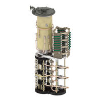
MR VACUTAP VR-Ex Installation And Commissioning Instructions (236 pages)
On-load tap-changer
Brand: MR
|
Category: Industrial Equipment
|
Size: 20 MB
Table of Contents
Advertisement
MR VACUTAP VR-Ex Installation And Commissioning Instructions (236 pages)
On-load tap-changer
Brand: MR
|
Category: Industrial Equipment
|
Size: 17 MB
Table of Contents

MR VACUTAP VR-Ex Installation And Commissioning Instructions (256 pages)
On-load tap-changer
Brand: MR
|
Category: Industrial Electrical
|
Size: 28 MB
Table of Contents
Advertisement

MR VACUTAP VR-Ex Operating Instructions Manual (88 pages)
On-load tap-changer
Brand: MR
|
Category: Transformer
|
Size: 15 MB
Table of Contents
Advertisement