MR VACUTAP VR-Ex Operating Instructions Manual
On-load tap-changer
Hide thumbs
Also See for VACUTAP VR-Ex:
- Installation and commissioning instructions (236 pages) ,
- Installation and commissioning instructions (256 pages) ,
- Installation and commissioning instructions (236 pages)

Related Manuals for MR VACUTAP VR-Ex


Summary of Contents for MR VACUTAP VR-Ex
- Page 1 On-load tap-changer ® VACUTAP VR-Ex Operating Instructions 7545646/00 EN . Irm 700…1 300 A, selector sizes RC/RD/RDE/RE/RF/RES...
- Page 2 © All rights reserved by Maschinenfabrik Reinhausen Dissemination and reproduction of this document and use and disclosure of its content are strictly prohibited unless expressly permitted. Infringements will result in liability for compensation. All rights reserved in the event of the granting of patents, utility models or designs.
-
Page 3: Table Of Contents
Table of contents Table of contents Introduction......................... 6 Manufacturer............................ 6 Completeness............................. 6 Safekeeping............................ 6 Notation conventions .......................... 7 1.4.1 Hazard communication system .......................... 7 1.4.2 Information system.............................. 8 1.4.3 Instruction system .............................. 8 Safety.......................... 10 Appropriate use .......................... 10 Inappropriate use.......................... 11 Fundamental safety instructions ....................... 11 Standards and regulations........................ - Page 4 Table of contents Commissioning......................... 34 Commissioning transformer at operating site ................... 34 4.1.1 Filling the oil compartment of the on-load tap-changer with insulating fluid............ 34 4.1.2 Bleeding on-load tap-changer head and suction pipe.................. 36 4.1.3 Checking motor-drive unit ........................... 37 4.1.4 Checking protective relay............................ 38 4.1.5 Commissioning the transformer .......................... 39 Operation...........................
- Page 5 Table of contents Drawings ........................... 67 Dimensional drawings........................ 67 9.1.1 10017720 ................................ 68 9.1.2 10009917 ................................ 69 On-load tap-changer head........................ 70 9.2.1 720847 ................................ 71 9.2.2 720781 ................................ 72 9.2.3 895168 ................................ 73 9.2.4 892916 ................................ 74 9.2.5 723015 ................................ 75 9.2.6 720845 ................................ 76 9.2.7 766161 ................................ 77 Adjustment plans ..........................
-
Page 6: Introduction
1 Introduction 1 Introduction This technical file contains detailed descriptions for monitoring during opera- tion, fault elimination, and maintenance. It also includes safety instructions and general information about the prod- uct. Information about installation can be found in the installation and commis- sioning instructions. -
Page 7: Notation Conventions
1 Introduction 1.4 Notation conventions 1.4.1 Hazard communication system Warnings in this technical file are displayed as follows. 1.4.1.1 Warning relating to section Warnings relating to sections refer to entire chapters or sections, sub-sec- tions or several paragraphs within this technical file. Warnings relating to sections use the following format: Type of danger! WARNING... -
Page 8: Information System
1 Introduction Pictograms warn of dangers: Pictogram Definition Warning of a danger point Warning of dangerous electrical voltage Warning of combustible substances Warning of danger of tipping Warning of danger of crushing Table 2: Pictograms used in warning notices 1.4.2 Information system Information is designed to simplify and improve understanding of particular procedures. - Page 9 1 Introduction Aim of action ü Requirements (optional). ► Step 1 of 1. ð Result of step (optional). ð Result of action (optional). Multi-step instructions Instructions which consist of several process steps are structured as follows: Aim of action ü Requirements (optional). 1.
-
Page 10: Safety
2 Safety 2 Safety ▪ Read this technical file through to familiarize yourself with the product. ▪ This technical file is a part of the product. ▪ Read and observe the safety instructions provided in this chapter. ▪ Read and observe the warnings in this technical file in order to avoid func- tion-related dangers. -
Page 11: Inappropriate Use
2 Safety In the standard version, the on-load tap-changer is designed for sinusoidal 50/60 Hz alternating current with a curve form symmetrical to the zero axis and can switch 1.5 times the rated through-current I at its rated step voltage Exceeding the rated step voltage U for a short period by up to 10% is per- mitted if the rated through-current I... - Page 12 2 Safety Work area Untidy and poorly lit work areas can lead to accidents. ▪ Keep the work area clean and tidy. ▪ Make sure that the work area is well lit. ▪ Observe the applicable laws for accident prevention in the relevant coun- try.
-
Page 13: Standards And Regulations
2 Safety ▪ It is imperative that you consult with Maschinenfabrik Reinhausen GmbH because specific operating conditions apply to alternative insulating fluids. ▪ Only use conductive and grounded hoses, pipes, and pump equipment that are approved for flammable liquids. ▪ Only use lubricants and auxiliary materials approved by the manufacturer. ▪... - Page 14 2 Safety Equipment groups (number 2) Equipment in this category is intended for use in underground parts of mines as well as those parts of surface installations of such mines endangered by firedamp and/or combustible dust. Equipment in this category is intended for use in other areas in which explosive atmospheres may be present.
-
Page 15: Standards And Regulations
2 Safety Explosion group (number 6) EN/IEC Gases, vapors (examples) Min. ignition energy (mJ) Ammonia Acetic acid, acetone, benzene, diesel, 0.18 ethane, ether, fuel oil, hexane, meth- ane, petrol, petroleum, propane Ethylene, isoprene, town gas 0.06 Acetylene, carbon disulfide, hydrogen 0.02 Table 7: Explosion groups Temperature classes (number 7) -
Page 16: Measures For Ensuring Compliance With Explosion Protection Requirements
2 Safety 2.5 Measures for ensuring compliance with explosion protection requirements 2.5.1 Measures taken by the manufacturer Maschinenfabrik Reinhausen has taken the following measures for ensuring compliance with explosion protection requirements. You do not need to take any special measures in this regard. 2.5.1.1 Quality of the insulating oil in the on-load tap-changer The quality of the insulating oil required by IEC 60296 and the quality of the synthetic esters required by IEC 61099 in the oil compartment of the on-load... - Page 17 2 Safety 2.5.2.2 Setting up the on-load tap-changer oil system Operate the on-load tap-changer only with a suitable oil system. This di- verter switch oil system consists of the diverter switch oil compartment, pro- tective relay, and oil conservator of the on-load tap-changer. It ensures that enough insulating oil is present in the diverter switch oil compartment at all times.
- Page 18 2 Safety 2.5.2.3.1 Dehydrating breather The oil conservator must be equipped with a dehydrating breather in accor- dance with VDE 0532-216-5 with downward-leading outlet and a protection degree of at least IP66 in accordance with IEC 60529. 2.5.2.3.2 Level indicator The oil conservator must have a level indicator from which the minimum oil quantity required and the maximum quantity permitted, as well as the current oil level, can be read.
-
Page 19: Personnel Qualification
2 Safety 2.5.2.4 Corrosion protection measures Because further installation steps are required before operation of the on- load tap-changer, sufficient corrosion protection cannot be provided at cer- tain interfaces to the transformer when the device leaves the factory. Figure 2: On-load tap-changer head 1 Sealing surface on piping connec- 3 Contact surface on on-load tap- tion flange... - Page 20 2 Safety Electrically skilled person The electrically skilled person has a technical qualification and therefore has the required knowledge and experience, and is also conversant with the ap- plicable standards and regulations. The electrically skilled person is also pro- ficient in the following: ▪...
-
Page 21: Personal Protective Equipment
2 Safety 2.7 Personal protective equipment Personal protective equipment must be worn during work to minimize risks to health. ▪ Always wear the personal protective equipment required for the job at hand. ▪ Never wear damaged personal protective equipment. ▪ Observe information about personal protective equipment provided in the work area. -
Page 22: Product Description
3 Product description 3 Product description 3.1 Scope of delivery The product is packaged with protection against moisture and is usually de- livered as follows: ▪ Oil compartment with on-load tap-changer head and built-in diverter switch insert ▪ Selector ▪ Ex motor-drive unit ▪... -
Page 23: Design/Versions
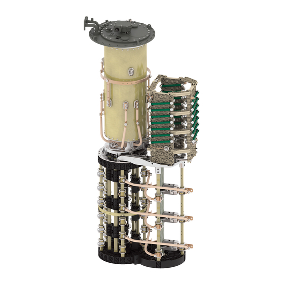
3 Product description Figure 3: System overview of on-load tap-changer, transformer 1 Transformer tank 6 Upper gear unit 2 Motor-drive unit 7 On-load tap-changer 3 Vertical drive shaft 8 Protective relay 4 Bevel gear 9 Oil conservator 5 Horizontal drive shaft 10 Active part of the transformer 3.2.2 Design/versions The following drawing shows the main components of the on-load tap-... - Page 24 3 Product description Figure 4: On-load tap-changer design 1 On-load tap-changer head 2 Upper gear unit 3 Pipe bend 4 Oil compartment 5 Tap selector 6 Change-over selector (optional) 7 On-load tap-changer head cover 8 Rupture disk ® VACUTAP VR-Ex 7545646/00 EN Maschinenfabrik Reinhausen GmbH 2020...
- Page 25 3 Product description 3.2.2.1 Pipe connections The on-load tap-changer head features 4 pipe connections for different pur- poses. Depending on the order, some or all of these pipe connections are fitted with pipe bends ex factory. All pipe bends can be freely swiveled once the pres- sure ring is loosened.
-
Page 26: Nameplate And Serial Number
3 Product description tween the transformer tank and oil compartment of the on-load tap-changer, which is necessary for drying, filling with insulating fluid and transportation of the transformer. 3.2.3 Nameplate and serial number The nameplate with serial number is on the on-load tap-changer head cover. Figure 6: Nameplate The serial number can also be found on the selector. - Page 27 3 Product description 3.2.4.1 Protective relay 3.2.4.1.1 Function description The protective relay is looped into the circuit breaker tripping circuit, thus protecting the on-load tap-changer and transformer in the event of a fault within the on-load tap-changer oil compartment. It is tripped when the speci- fied speed of flow from the on-load tap-changer head to the oil conservator is exceeded due to a fault.
- Page 28 3 Product description Rear view Figure 9: RS 2001-Ex 1 Ground connection 2 Nameplate View from above Figure 10: RS 2001-Ex 1 Gasket 2 Potential tie-in 3 Terminal box cover 4 Slotted head screw for potential tie-in 5 OPERATION (reset) test button 6 Slotted head screw for protective cover 7 OFF (test tripping) test button...
-
Page 29: Drive Shaft
3 Product description 3.2.4.1.3 Name plate The name plate for the explosion-protected protective relay is on the rear of the product. Figure 11: Position of name plate 3.2.4.2 Rupture disk The rupture disk is a pressure relief device without signaling contact in ac- cordance with IEC 60214-1 and is located in the on-load tap-changer head cover. - Page 30 3 Product description The explosion-proof drive shaft consists of a square tube with insulator and is coupled by two coupling brackets and one coupling bolt at both ends to the drive or driven shaft end of the device to be connected. Figure 12: Explosion-proof drive shaft with insulator ®...
-
Page 31: Design/Model
3 Product description 3.3.2 Design/Model The design of the explosion-proof drive shaft is described in this section. Figure 13: Components of the explosion-proof drive shaft 1 Bevel gear 2 Hose clip 3 Screws 4 Telescopic protective tube 5 Coupling bracket 6 Insulator 7 Double coupling bracket 8 Square tube 9 Pin... - Page 32 3 Product description Configuration V 1 min Intermediate bearing Middle of hand crank – middle of 706 mm If the maximum value of bevel gear (maximum permissible 2472 mm is exceeded, the axial offset 2°) use of an intermediate bearing is necessary. V 1 ≤ 2472 mm (without in- termediate bearing) V 1 >...
-
Page 33: Identification Plate
3 Product description 3.3.3 Identification plate The identification plate is on the telescopic protective tube. Figure 14: Position of the identification plate ® Maschinenfabrik Reinhausen GmbH 2020 7545646/00 EN VACUTAP VR-Ex... -
Page 34: Commissioning
4 Commissioning 4 Commissioning WARNING Danger of explosion! Explosive gases in the oil compartment of the on-load tap-changer, trans- former, pipework system, oil conservator and at the dehydrating breather opening can deflagrate or explode and result in severe injury or death! ►... - Page 35 4 Commissioning 1. Establish a connecting lead between pipe connection E2 and one of the pipe connections R, S or Q to ensure equal pressure in the oil compart- ment and transformer during evacuation. Figure 15: Connecting lead between E2 and Q 2.
-
Page 36: Bleeding On-Load Tap-Changer Head And Suction Pipe
4 Commissioning 5. Determine the dielectric strength and water content at a sample tempera- ture of 20°C ± 5°C. The dielectric strength and water content must comply with the limit values [►Section 8.3, Page 66] specified in the technical data. 4.1.2 Bleeding on-load tap-changer head and suction pipe 4.1.2.1 Bleeding on-load tap-changer head 1. -
Page 37: Checking Motor-Drive Unit
4 Commissioning 4.1.2.2 Bleeding suction pipe on pipe connection S 1. Remove screw cap from pipe connection S. Figure 19: Screw cap NOTICE! An incompletely bled suction pipe significantly impairs the insu- lation capability of the on-load tap changer to ground. Open vent screw and bleed suction pipe completely. -
Page 38: Checking Protective Relay
Tests on the motor-drive unit 1. Perform function checks as described in relevant MR operating instruc- tions for motor-drive unit. NOTICE! An incorrectly coupled motor-drive unit will lead to damage to the on-load tap-changer. -
Page 39: Commissioning The Transformer
4 Commissioning 8. Press IN SERVICE test button. 9. Leave the transformer's danger zone. 10. Close the transformer's circuit breaker with isolating switches open and the transformer grounded on all sides. 11. Press OFF test button. 12. Ensure that the transformer's circuit breaker is open. ð... -
Page 40: Operation
5 Operation 5 Operation 5.1 Actuating motor-drive unit with hand crank WARNING Danger of explosion! Unauthorized operation of the motor-drive unit with the hand crank may re- sult in death or serious injury. ► Only ever open the motor-drive unit when it is de-energized and wait at least 30 minutes after the voltage supply has failed or the motor-drive unit has been switched off before you open it. - Page 41 5 Operation Operating the motor-drive unit with the hand crank To carry out a tap-change operation with the hand crank, proceed as follows: ü Ensure that the protective gas supply has been switched off. 1. Open the door of the protective housing for the motor-drive unit. 2.
-
Page 42: Fault Elimination
In the event of faults on the on-load tap-changer and motor-drive unit which cannot be easily corrected on site, or if the protective relay or additional pro- tective devices have been tripped, please inform your authorized MR repre- sentative, the transformer manufacturer or contact MR directly. - Page 43 Contact MR in the event of noise from the motor-drive unit. Red message on monitoring unit If possible read out database and send to MR along with error code. Warning or tripping of Buchholz relay on transformer Notify manufacturer of transformer.
-
Page 44: Tripping The Protective Relay And Re-Commissioning The Transformer
6 Fault elimination 6.1 Tripping the protective relay and re-commissioning the transformer WARNING Danger of explosion! Explosive gases in the protective relay can deflagrate or explode and result in severe injury or death. ► Wait 15 minutes after switching off the transformer before beginning fur- ther work on the protective relay so that the gases can dissipate. -
Page 45: Flap Valve In Off Position
6 Fault elimination 6.1.2 Flap valve in OFF position If the flap valve is in the OFF position, proceed as follows: 1. Ensure that the transformer is not started up under any circumstances. 2. Contact and inform Maschinenfabrik Reinhausen of the following: ð... -
Page 46: Maintenance
7 Maintenance 7 Maintenance DANGER Electric shock! An energized transformer could cause death or serious injuries. ► Switch off transformer on high and low-voltage side. ► Lock transformer to prevent unintentional restart. ► Ensure that everything is de-energized. ► Visibly connect all transformer terminals to ground (grounding leads, grounding disconnectors) and short circuit them. -
Page 47: Inspection
7 Maintenance 7.1 Inspection Monitoring the on-load tap-changer and motor-drive unit is limited to occa- sional visual checks of on-load tap-changer head, protective relay, and mo- tor-drive unit. For efficiency reasons these visual inspections can be com- bined with the usual checks on the transformer. Check the following: Interval Action... -
Page 48: Maintenance Intervals
"Changing the insulating fluid" section. Table 11: Inspection plan 7.2 Maintenance intervals Maintenance intervals without MR monitoring system WARNING Danger of explosion! If pending maintenance work is not carried out immediately, this may lead to death or serious injury as a result of a progressive short circuit, for example. - Page 49 7 Maintenance If you are operating the on-load tap-changer without an MR monitoring sys- tem, the following maintenance intervals shall apply. Interval Action after 150,000 switching operations (mo- Maintenance of the on-load tap-changer tor-drive unit counter reading) after 1.2 million switching operations...
-
Page 50: Changing The Insulation Fluid
MR monitoring system issues a maintenance warning. ► In the event of failure or shutdown of the MR monitoring system, observe the maintenance intervals as specified in the maintenance plan without the MR monitoring system. - Page 51 7 Maintenance 1. Loosen hose clips on protective cover of horizontal drive shaft, remove protective cover. Figure 21: Removing protective cover ® Maschinenfabrik Reinhausen GmbH 2020 7545646/00 EN VACUTAP VR-Ex...
-
Page 52: Emptying The Oil Compartment And Oil Conservator
7 Maintenance 2. Depending on version, loosen 4 or 6 screws on coupling brackets to upper gear unit and bevel gear. Figure 22: Loosening coupling brackets 3. Remove horizontal drive shaft. Be sure not to lose the coupling bolts. Figure 23: Removing drive shaft 7.3.3 Emptying the oil compartment and oil conservator 1. - Page 53 7 Maintenance 4. Once the gas has been discharged and insulating fluid is flowing out of the air-vent valve, close the air-vent valve. 5. Close the stop-cock between the oil conservator and on-load tap-changer. 6. Open air-vent valve E1 again and extract approximately 5–10 liters of in- sulating fluid via the pipe connection S until the area under the on-load tap-changer head cover is free of insulating fluid.
-
Page 54: Filling The Oil Compartment And Oil Conservator With Fresh Insulating Fluid
7 Maintenance 7.3.4 Filling the oil compartment and oil conservator with fresh insulating fluid NOTICE Damage to the on-load tap-changer! Unsuitable insulating fluids cause damage to the on-load tap-changer. ► Use insulating fluids that meet the requirements in accordance with IEC 60296. - Page 55 7 Maintenance 4. Position the on-load tap-changer head cover on the on-load tap-changer head in such a way that the red triangular markings on the on-load tap- changer head and the on-load tap-changer head cover are aligned. Figure 27: Triangular markings and o-ring 5.
- Page 56 7 Maintenance 9. Remove screw cap from pipe connection S. Figure 29: Pipe connection S 10. Open vent screw and bleed piping. 11. Close vent screw. 12. Seal vent screw with screw cap. 13. Check the level in the oil conservator and top up with insulating fluid if necessary.
-
Page 57: Installing Horizontal Drive Shaft
7 Maintenance 7.3.5 Installing horizontal drive shaft 1. Secure horizontal drive shaft between upper gear unit and bevel gear with coupling brackets and 4 or 6 screws. Refer to the drive shaft operating in- structions for details. Figure 30: Securing drive shaft ®... -
Page 58: Centering On-Load Tap-Changer And Motor-Drive Unit
3. For special design types featuring cardan shafts, be sure to check the ex- pansion bellows and the lubricant reservoir of the cardan shafts. You will find a detailed description of how to fit the drive shaft in the MR op- erating instructions "Drive shaft". - Page 59 7 Maintenance Perform the DC resistance measurement in various on-load tap-changer op- erating positions. You need to distinguish here whether the measured cur- rent is interrupted when changing operating position or not. Status of oil compart- Without interruption in With interruption (mea- ment measured current sured current = 0 A be-...
-
Page 60: Technical Data
8 Technical data 8 Technical data An overview of all key technical data for the on-load tap-changer and motor- drive unit exists in the form of separate documents, which are available on request. 8.1 Technical data for on-load tap-changer 8.1.1 On-load tap-changer properties The VACUTAP®... - Page 61 8 Technical data Rated peak withstand current [kA] Maximum rated step voltage U 4 500 4 500 4 500 4 500 Step capacity P [kVA] 3 000 3 000 3 000 6 000 Rated frequency [Hz] 50…60 Table 15: Electrical data for VACUTAP® VRM I/II/III Forced current splitting by two parallel winding branches required.
-
Page 62: Permissible Ambient Conditions
8 Technical data Maximum rated step voltage 6 000 6 000 6 000 12 000 12 000 Step capacity P [kVA] 3 000 6 000 12 000 6 000 12 000 Rated frequency [Hz] 50…60 Table 17: Electrical data for VACUTAP® VRH/VRX I/II/III Forced current splitting by two parallel winding branches required. -
Page 63: Technical Data For Protective Relay
8 Technical data 8.2 Technical data for protective relay The technical data for the protective relay RS 2001-Ex is listed in the follow- ing. In accordance with DIN EN 60255-1, operational accuracy = base accu- racy Housing Outdoor model Degree of protection IP 66 Relay actuation Flap valve with aperture Vibration immunity... - Page 64 8 Technical data Dielectric strength AC dielectric strength between all volt- 2,500 V, 50 Hz, test duration 1 minute age-carrying connections and the grounded parts AC dielectric strength between the 2,000 V, 50 Hz, test duration 1 minute opened contacts Table 23: Dielectric strength Electrical data DC switching capacity...
-
Page 65: Protective Relay With Several Dry-Reed Magnetic Switches
8 Technical data 8.2.1 Protective relay with several dry-reed magnetic switches The protective relay can be supplied with several independent dry-reed mag- netic switches. These can be designed as normally open (NO) or normally closed (NC) contacts and are electrically isolated (see dimensional drawing supplied). -
Page 66: Limit Values For Dielectric Strength And Water Content Of Insulating Fluids
8 Technical data 8.3 Limit values for dielectric strength and water content of insulating fluids The following tables specify the limit values for dielectric strength (measured in accordance with IEC 60156) and water content (measured in accordance ® with IEC 60814) of insulating fluids for the VACUTAP on-load tap-changer. -
Page 67: Drawings
9 Drawings 9 Drawings 9.1 Dimensional drawings ® Maschinenfabrik Reinhausen GmbH 2020 7545646/00 EN VACUTAP VR-Ex... - Page 68 Ra 3,2 PROTECTIVE RELAY MOUNTING FLANGE ON TRANSFORMER COVER M12 FIXING SCREW ON-LOAD TAP-CHANGER HEAD GASKET POSITION INDICATOR, REMOVE BEFORE REMOVING THE DIVERTER SWITCH INSERT INSPECTION WINDOW O 15 HOLES SUCTION PIPE 34,5 ON-LOAD TAP-CHANGER HEAD COVER SCREW COVER GASKET ON-LOAD TAP-CHANGER HEAD COVER CENTRAL GEAR UNIT WITH 25a DRIVE SHAFT PIPE CONNECTION R FOR PROTECTIVE RELAY...
- Page 69 DIMENSION SERIAL NUMBER SELECTOR SIZE RC/RD/RDE/RE/RF IN mm SELECTOR CONNECTION CONTACT MATERIAL NUMBER SHEET EXCEPT AS DIMENSION DRAWING 100099170E 1 1 / NOTED...
-
Page 70: On-Load Tap-Changer Head
9 Drawings 9.2 On-load tap-changer head ® VACUTAP VR-Ex 7545646/00 EN Maschinenfabrik Reinhausen GmbH 2020... - Page 72 Um [kV] 170 / 245 / 300 362 / 420 ø56 ø100 DIMENSION [mm] ø620 ø695 O-RING 44,2 - 5,7 LIFTING DEVICE O-RING TRANSFORMER COVER SCREENING RING ONLY WITH Um=170/245/300/362/420 kV O 750 SUPPORTING FLANGE LIFTING DEVICE Z = CENTERING BOLT DRIVE SIDE OF SELECTOR SERIAL NUMBER ON-LOAD TAP-CHANGER VACUTAP®...
- Page 73 O 235 O 152,5 1: 1 GASKET 4,25 x 178,5 x 200 DRIVE SIDE OF SELECTOR MA = 50 Nm O 262 SERIAL NUMBER ON-LOAD TAP-CHANGER DIMENSION IN mm OILTAP® M, MS, R, RM AND VACUTAP® VR®, VM®, VMS® MATERIAL NUMBER SHEET EXCEPT AS...
-
Page 78: Adjustment Plans
9 Drawings 9.3 Adjustment plans ® VACUTAP VR-Ex 7545646/00 EN Maschinenfabrik Reinhausen GmbH 2020... - Page 79 THE CONNECTION DIAGRAM OF THE ON-LOAD TAP-CHANGER IS BINDING FOR THE DESIGNATION AND ON-LOAD THE EQUIPMENT OF THE TERMINALS TAP-CHANGER AND PHASES. HEAD = DRIVE SIDE OF THE SELECTOR = ON-LOAD TAP-CHANGER TAKE-OFF TERMINAL DIVERTER SWITCH INSERT TOP VIEW 1 SECTOR 2 SECTORS 3 SECTORS DIVERTER SWITCH...
- Page 80 THE CONNECTION DIAGRAM OF THE ON-LOAD TAP-CHANGER IS BINDING FOR THE DESIGNATION AND ON-LOAD THE EQUIPMENT OF THE TERMINALS TAP-CHANGER AND PHASES. HEAD = DRIVE SIDE OF THE SELECTOR = ON-LOAD TAP-CHANGER TAKE-OFF TERMINAL DIVERTER SWITCH INSERT TOP VIEW 3 SECTORS 1 SECTOR 2 SECTORS DIVERTER SWITCH...
- Page 81 THE CONNECTION DIAGRAM OF THE ON-LOAD TAP-CHANGER IS BINDING FOR THE DESIGNATION AND ON-LOAD THE EQUIPMENT OF THE TERMINALS TAP-CHANGER AND PHASES. HEAD = DRIVE SIDE OF THE SELECTOR = ON-LOAD TAP-CHANGER TAKE-OFF TERMINAL DIVERTER SWITCH INSERT TOP VIEW 1 SECTOR 3 SECTORS 2 SECTORS DIVERTER SWITCH...
- Page 82 THE CONNECTION DIAGRAM OF THE ON-LOAD TAP-CHANGER IS BINDING FOR THE DESIGNATION AND ON-LOAD THE EQUIPMENT OF THE TERMINALS TAP-CHANGER AND PHASES. HEAD = DRIVE SIDE OF THE SELECTOR = ON-LOAD TAP-CHANGER TAKE-OFF TERMINAL DIVERTER SWITCH INSERT TOP VIEW 1 SECTOR 2 SECTORS 3 SECTORS DIVERTER SWITCH...
- Page 83 THE CONNECTION DIAGRAM OF THE ON-LOAD TAP-CHANGER IS BINDING FOR THE DESIGNATION AND ON-LOAD THE EQUIPMENT OF THE TERMINALS TAP-CHANGER AND PHASES. HEAD = DRIVE SIDE OF THE SELECTOR = ON-LOAD TAP-CHANGER TAKE-OFF TERMINAL DIVERTER SWITCH INSERT TOP VIEW 3 SECTORS 1 SECTOR 2 SECTORS DIVERTER SWITCH...
- Page 84 THE CONNECTION DIAGRAM OF THE ON-LOAD TAP-CHANGER IS BINDING FOR THE DESIGNATION AND ON-LOAD THE EQUIPMENT OF THE TERMINALS TAP-CHANGER AND PHASES. HEAD = DRIVE SIDE OF THE SELECTOR = ON-LOAD TAP-CHANGER TAKE-OFF TERMINAL DIVERTER SWITCH INSERT TOP VIEW 1 SECTOR 3 SECTORS 2 SECTORS DIVERTER SWITCH...
-
Page 85: Glossary
Glossary Glossary Direct current Ingress protection Dielectric strength Material-specific property of isolators [kV/2.5 Maschinenfabrik Reinhausen GmbH mm]; maximum electrical field strength without a breakdown (arc) Normally Closed contact The International Electrotechnical Commission (IEC for short) is involved in the preparation and Normally Open contact publication of international standards for electri- cal, electronic and related technologies. - Page 88 Maschinenfabrik Reinhausen GmbH Falkensteinstrasse 8 93059 Regensburg +49 (0)941 4090-0 sales@reinhausen.com www.reinhausen.com ® 7545646/00 EN - VACUTAP VR-Ex - - 08/20 - Maschinenfabrik Reinhausen GmbH 2020 THE POWER BEHIND POWER.
Need help?
Do you have a question about the VACUTAP VR-Ex and is the answer not in the manual?
Questions and answers