Advertisement
Quick Links
Advertisement

Related Manuals for Iridium 9523


Summary of Contents for Iridium 9523
- Page 1 Iridium 9523/9523N L-Band Transceiver I n t e g r a t o r D e v e l o p me n t G u i d e V e r s i o n 7 . 4 Proprietary & Confidential Information...
- Page 2 Revis ion 7 .4 LEGAL DISCLAIMER AND CONDITIONS OF USE This document contains information for the Iridium Core 9523/9523N (“Product”) and is provided “as is.” The purpose of providing such information is to enable Value Added Resellers and Value Added Manufacture rs (collectively, “Product Developer(s)”) to understand the Product and how to integrate it into a wireless...
-
Page 3: Export Compliance Information
Iridium 9523/9523N L-Band Tra nsce iver Integrator Devel opme nt Guide Revis ion 7 .4 Export Compliance Information This Product is controlled by the export laws and regulations of the United States of America. The U.S. Government may restrict the export or re-export of this Product to certain individuals and/or destinations . - Page 4 Iridium 9523/9523N L-Band Tra nsce iver Integrator Devel opme nt Guide Revis ion 7 .4 Con ten ts Revision History Product Overview Key Features Iridium Core 9523/9523N Packaging and Regulatory Certification Software Revision Unauthorized Changes Radio Interference RF Exposure FCC Class B Digital Device Notice...
- Page 5 Iridium 9523/9523N L-Band Tra nsce iver Integrator Devel opme nt Guide Revis ion 7 .4 RF Interface RF Connector Type 4.1.1 Antenna Characteristics RF Interface Specifications Radio Characteristics S-meter Performance AT Interface Proprietary & Confidential Information Distribution of guide restricted to product dev elopers only . Inf ormation contained in this guide is subject to change without notice.
- Page 6 Data Communications Equipment. In this Product, DCE refers to the Iridium Core 9523 (V.24 signal) Data Set Ready. This signal, from the Iridium Core 9523, indicates readiness to accept communication over the data port Data Terminal Equipment. In this Product, DTE refers to the FA (V.24 signal) Data Terminal Ready.
- Page 7 ‘Iridium Core 9523/9523N’. Where the contents of this document apply specifically to either the Iridium Core 9523 or Iridium Core 9523N then this is indicated by the use of the terms ‘Iridium Core 9523’ and ‘Iridium Core 9523N’ respectively.
- Page 8 Iridium 9523/9523N L-Band Tra nsce iver Integrator Devel opme nt Guide Revis ion 7 .4 Table 1: Iridium Core 9523 Regulatory and Technical Certifications Electrical / Regulatory Mechanical / Radio Tests EMC Tests Approvals Operational Safety Tests ETSI EN 301 489-1 V1.8.1 (2008-04) ETSI EN 301 441 V1.1.1...
- Page 9 Product Developers should read this document in conjunction with the “Software Release Notes” relevant to the revision of the software that is loaded into their Iridium Core 9523/9523N. The software release notes are available on the Iridium for Partners section of the Iridium.com website.
- Page 10 Iridium 9523/9523N L-Band Tra nsce iver Integrator Devel opme nt Guide Revis ion 7 .4 RF Exposure This equipment complies with FCC and IC radiation exposure limits set forth for an uncontrolled environment. The antenna should be installed and operated with minimum distance of 20 cm between the radiator and your body.
- Page 11 Iridium 9523/9523N L-Band Tra nsce iver Integrator Devel opme nt Guide Revis ion 7 .4 Labelling Requirements for the Host device The host device shall be properly labelled to identify the modules within the host device. The certification label of the module shall be clearly visible at all times when installed in the host device, otherwise the host device must be labelled to display the FCC ID and IC of the module, preceded by the words "Conta ins transmitter...
- Page 12 Revis ion 7 .4 R&TTE Statement Iridium Communications Inc. hereby declares that the 9523N is in compliance with the essential requirements and other relevant provisions of Directive1999/5/EC. A copy of the Declaration of Conformity is given below. Proprietary & Confidential Information...
- Page 13 Iridium 9523/9523N L-Band Tra nsce iver Integrator Devel opme nt Guide Revis ion 7 .4 Reference ITU-T Recommandation V.25ter, 08/95 ETS 300 642: Digital Cellular Telecommunications System (Phase 2); AT C ommand Set for GSM Mobile Equipment (GSM 07.07) ETS 300 585: Digital Cellular Telecommunications System (Phase 2); Use of DTE-DCE Interface SMS and CBS (GSM 07.05)
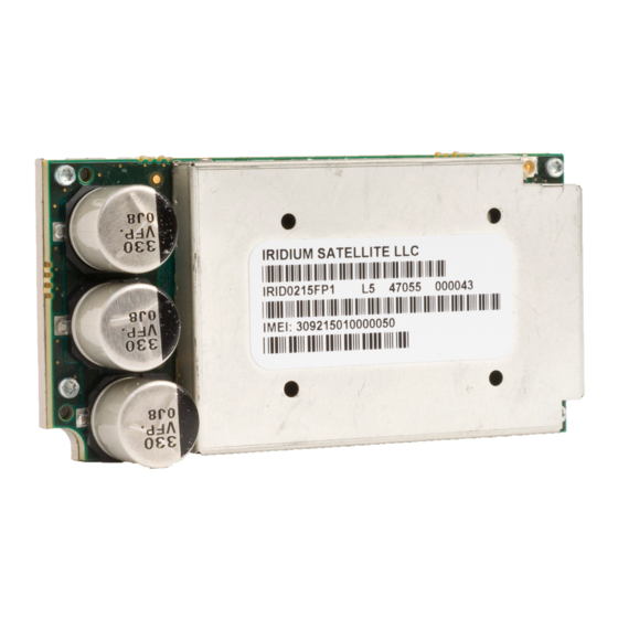
- Page 14 Revis ion 7 .4 Physical Specification For illustrative purposes, pictures of the Iridium Core 9523 and Iridium Core 9523N, fitted with its aluminum shielding frame, are shown in Figure 1 and Figure 2 respectively. Figure 1: Photos of Iridium Core 9523...
- Page 15 Iridium 9523/9523N L-Band Tra nsce iver Integrator Devel opme nt Guide Revis ion 7 .4 Figure 2: Photos of Iridium Core 9523N Top View Bottom View Left View Proprietary & Confidential Information Distribution of guide restricted to product dev elopers only . Inf ormation contained in this guide is subject to change without notice.
- Page 16 The two height values provided in Table 3 do not include the height of the compressible gasket on the bottom of the Iridium Core 9523/9523N that will mate to the FA board. It is assumed that this gasket will compress to near zero thickness if screws are torqued sufficiently.
- Page 17 Figure 3: Dimensions of the Iridium Core 9523/9523N (Dimensions in millimeters) Part Numbering The part numbers for the Iridium Core 9523/9523N are as shown in Table 4. The part number is stated on the product label. Table 4: Iridium Core 9523/9523N Part Numbering...
- Page 18 The layout of the mounting location for the Iridium Core 9523/9523N on the FA board – including the locations and diameters of all nine holes, layout of the grounding ring, and identification of areas with different grounding requirements –...
- Page 19 Iridium Core 9523/9523N may exceed 70ºC. In the case where the ambient temperature in the host product incorporating the Iridium Core 9523/9523N can exceed 50ºC, the host product must prevent direct access to the Iridium Core 9523/9523N module by the end user/operator in order to comply with EN 60950-1 clause 4.5.
-
Page 20: Environmental Specification
Environmental Tests An Iridium system that incorporates the Iridium Core 9523 has passed the tests listed in Table 6. The Iridium Core 9523N has passed the tests in Table 7. It is expected that a system incorporating the Iridium Core 9523/9523N designed according to this document should also pass these tests. - Page 21 Iridium 9523/9523N L-Band Tra nsce iver Integrator Devel opme nt Guide Revis ion 7 .4 Table 7: Iridium Core 9523N Environmental Tests Test Name Test Reference Test Description Change of Temperature Five cycles of 1 hour each from -30°C to +70°C.
- Page 22 Iridium 9523/9523N L-Band Tra nsce iver Integrator Devel opme nt Guide Revis ion 7 .4 Test Name Test Reference Test Description Temperature Shock Soak at -40ºC for 4 hours. Transfer to +85ºC and soak for an additional 4 hours. Repeat 4 times (4 cold to Method 503.5...
- Page 23 Data sheets on these connectors can be found at: http://www.molex.com Pin numbering schemes for the Molex connectors on the Iridium Core 9523/9523N and the host FA board are shown in Figure 6 (both pictures show the pin-out when looking down onto the boards).
- Page 24 Figure 7 provides a reference for the pin designation and shows the connector’s location and rotation with respect to the corner of the Iridium Core 9523/9523N board. This view is for illustrative purposes only. This view designation is when looking into the user connector towards the Iridium Core 9523/9523N.
- Page 25 Iridium 9523/9523N L-Band Tra nsce iver Integrator Devel opme nt Guide Revis ion 7 .4 Signal direction Signal Name Signal function Signal group (WRT modem) CODEC_PCMCLK Clock PCM audio port 1 CODEC_PCMIN Data from modem PCM audio port 1 CODEC_PCMSYNC...
- Page 26 Table 12. The Iridium Core 9523/9523N produces the logic signal PA_BOOST_EN to indicate when the external Boost Power voltage must be applied. This signal can be used as the enable signal to an external boost regulator (logic high = VBOOST needed, logic low = VBOOST not needed).
-
Page 27: Typical Power Usage Profile
The Iridium Core 9523/9523N starts up when power is applied and the TRX_ON input is high. As long as the input voltage is applied, logic high on this line turns the Iridium Core 9523/9523N on and a logic low turns it off. - Page 28 The current peak in the VBOOST rail lasts for 8.3ms and repeats every 90ms (this is the period of a frame in the Iridium air interface). When not transmitting, the VBOOST current returns to zero. The VBOOST current was measured when the Iridium Core 9523/9523N was connected to a 27V power source that could meet its instantaneous power requirements (around 25W).
- Page 29 20ms, as it maintains synchronization with the signal from the satellites. When an Iridium call is in progress, there are two peaks in the current drawn by the VBAT rail in each 90ms frame – one of about 300mA during the transmit time-slot and a slightly smaller one, 250mA, during the receive time-slot.
-
Page 30: Signal Function
PCM Digital Audio The Iridium Core 9523/9523N has two PCM digital audio ports, though only one of these can be in use at any time. The active port is selected using the AT+CAR command. This setup allows the FA board to provide two parallel audio paths and switch between them through software instead of hardware. - Page 31 UC_DATX PCM data input UC_DARX Note: the data signal names on Port 2 are defined from the point of view of the Iridium Core 9523/9523N. 3.3.3 11Hz Signal for Manufacturing and Regulatory Testing An external ‘frame tick’ signal needs to be passed to the Iridium Core 9523/9523N during regulatory radio testing of the host system, and possibly also during manufacturing testing.
- Page 32 External GPS Receiver Switch If the Iridium Core 9523/9523N is used near a GPS receiver, it is possible that the input circuitry of the GPS receiver could be damaged by the output power of the Iridium transmitter, especially if the two devices share a single antenna.
- Page 33 Additional information can be found at: http://www.i-pex.com Note that the RF connector on the Iridium Core 9523/9523N is not mounted directly to the FA board along with the user interface connector. It must be attached to the FA board through a coaxial cable.
- Page 34 4. If the reading is near the decision threshold it would be easy to see a 1 bar difference. AT Interface The Iridium Core 9523/9523N is configured and operated through the use of AT commands. See the ISU AT Command Reference for the full set of AT commands and responses. For differences in AT command support between Iridium Core 9523/9523N software releases, see the relevant software release notes, which are made available to authorized Iridium VARs and VAMs on the Iridium Developer Extranet.
Need help?
Do you have a question about the 9523 and is the answer not in the manual?
Questions and answers