Table of Contents

Related Manuals for Iridium NAL Research Corporation 9602-NAL


Summary of Contents for Iridium NAL Research Corporation 9602-NAL
- Page 1 451-92695-001A 9602-NAL User Guide Version A March 28, 2022 Copyright © 2021 by NAL Research Corporation Powered by 11100 Endeavor Ct., Suite 300 Manassas, Virginia 20109 USA Phone: 703-392-1136 Email: contact@nalresearch.com...
- Page 2 Product (including hardware, software and/or firmware) and/or the Iridium satellite, or arising out of or in connection with the ability or inability to use the Product (including hardware, software and/or firmware) and/or the Iridium satellite to the fullest extent these damages may be disclaimed by law and whether advised of the possibilities of such damages.
- Page 3 9602-N User Guide Version A EVISION ISTORY Revision Date Description Author 1.0.1 02/25/2013 Initial version A. Schiltz - Updated to new template; editorial update. A. Schiltz, 03/28/2022 A. Nguyen - Formal release Document Number: 451-92695-001A 3 of 40...
- Page 4 9602-N User Guide Version A EFERENCE OCUMENTS The latest revisions of the NAL documents are available from the NAL Research website at https://www.nalresearch.com/support/documentation-downloads/. Reference Title Revision/Date Product Information Model 9602-N 2019 AT Commands for Models 9602 (TN2010-111-V1.0) Version 1.0, 2010 SatTerm Software Manual (TN2009-19-V7.0) Version 8.9.7, 2022 Additional Information on DirectIP SBD (TN2007-637-...
-
Page 5: Table Of Contents
Appendix A: Power Consumption of the 9602-NAL ............... 25 Appendix B: Standards Compliance ..................29 Appendix C: Export Compliance ................... 30 Appendix D: The Iridium Network ..................31 Iridium Network Data Capabilities ....................32 Dial-up Data Service ........................33 Direct Internet Connection ......................35 Short Burst Data .......................... - Page 6 Figure 9: Current Drawn During Standby..................27 Figure 10: Current Drawn During SBD ..................27 Figure 11: Current Drawn During Sleep ..................28 Figure 12: Iridium Network Major Components ................31 Figure 13: Iridium Network Data Capabilities ................33 Figure 14: PSTN Dial-up Connectivity ................... 34 Figure 15: Iridium Dial-up Data Service ..................
- Page 7 FDMA ......Frequency-Division Multiple Access GND ......Ground GPS ......Global Positioning System GSM ......Global System for Mobile Communications I/O ......Input/Output IP ........Internet Protocol ISU ......Iridium Subscriber Unit kbps ......Kilobits Per Second LAN ......Local Area Network LED ......Light-Emitting Diode LNA ......Low-Noise Amplifier Document Number: 451-92695-001A...
- Page 8 9602-N User Guide Version A MT-SBD ......Mobile-Terminated Short-Burst Data NIPRNet ......Non-classified Internet Protocol Router Network OFAC ......Office of Foreign Asset Controls PDA ......Personal Digital Assistant PPP ......Point-To-Point Protocol PSTN ......Public Switched Telephone Network PWR ......Power RI ........Ring Indicator RF........Radio Frequency RHCP ......Right-Handed Circular Polarization RTS ......Request To Send RUDICS .......Router-Based Unrestricted Digital Internetworking Connectivity Solution...
-
Page 9: Introduction
Iridium 9602 transceiver with an extended input voltage range, and only allows Short Burst Data (SBD connectivity to the Iridium satellite network. It does not support voice, circuit-switched data, or Short Message Service (SMS). Similar to a standard landline modem, the 9602-NAL can be controlled by any Data Terminal Equipment (DTE) capable of sending standard AT commands via an RS232 serial port. -
Page 10: Mechanical Interfaces
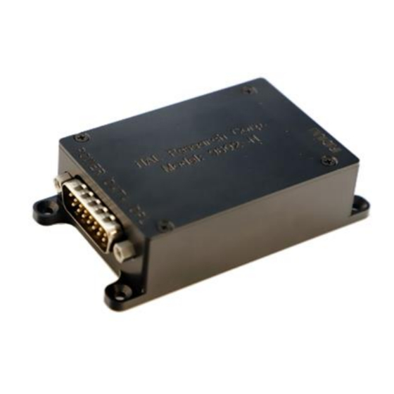
The 9602-NAL is intended to be used as a modem connected to a DTE via an RS232 serial interface. The 9602-NAL incorporates two different connectors—a multi-interface connector and a SubMiniature version A (SMA) Iridium antenna connector—as shown in Figure 1. When requested, an SMA Global Positioning System (GPS) pass-through connector can be installed as an option (see section 5). -
Page 11: Multi-Interface Connector
9602-N User Guide Version A ULTI NTERFACE ONNECTOR The multi-interface connector is a male 15-pin miniature D-Sub type (DB-15 connector) that includes five interfaces—DC power input, power on/off control, RS232 data interface, network availability output, and supply power indicator output. Individual pin assignments are summarized in Table 1. -
Page 12: Rs232 Data Interface (3-Wire Configuration)
9602-N User Guide Version A DTE can monitor this pin and use appropriate AT commands to retrieve the MT-SBD message. The 9602-NAL does not support autobaud. Set the baud using the AT+IPR command. The factory-set baud is 19.2 kbps. RS232 D (3-W NTERFACE ONFIGURATION... -
Page 13: Figure 2: Power Input Settings
9602-N User Guide Version A when the jumper is on the right pin. Both power pins on the multi-interface connector and their corresponding voltage settings on the jumper must be used for the unit to power up properly. Jumper used to set input voltage range Figure 2: Power Input Settings... -
Page 14: Power On/Off Control
9602-N User Guide Version A Figure 3: Model HRC-24-11 Data/Power Cable Assembly Power reset by the 9602-NAL during an SBD session indicates the power source is unable to sustain required peak current demand. OWER ONTROL The 9602-NAL is shipped with hardware set for automatic startup when power is applied, whether the voltage setting is for +5 VDC or for +6.5 VDC to +32 VDC. -
Page 15: Dc Supply Indicator Output
9602-NAL can successfully receive the Ring Channel, or, put more simply, it can see an Iridium satellite. Network Available is not a guarantee that a message is successfully sent. The Network Available state is evaluated every time the Ring Channel is received or missed. If the Ring Channel is visible, then it is updated every four seconds. -
Page 16: S-Meter Performance
9602-N User Guide Version A currently visible, then the update period can be as long as two minutes, depending on how long the lack of satellite visibility existed. This is because the 9602-NAL attempts to conserve power by increasing the ring-search interval while the satellites are not visible. Every time a ring search fails, the time to wait is increased until it reaches a limit at 120 seconds. -
Page 17: Iridium Antenna Connector
3 dB at the operating frequency of 1616 to 1626.5 MHz. Implementation loss higher than this will affect the Iridium link performance and quality of service. Connect the 9602-NAL to an antenna with the characteristics shown in Table 2. -
Page 18: Table 3: Custom Antenna Characteristics Required
9602-N User Guide Version A If the specific application requires a custom antenna, it must meet the following characteristics in Table 3. Table 3: Custom Antenna Characteristics Required Parameter Value Operating Temperature Range –40°C/+85°C without loss of function Measurement Frequency Range 1616 to 1626.5 MHz Return Loss (Minimum) 9.5 dB (<1.5:1 VSWR) -
Page 19: Gps Pass-Through
Iridium antenna path. It is provided for GPS receivers with the ability to share the Iridium antenna. An overview of this circuit is provided in Figure 6. Select a wideband Iridium antenna with appropriate sensitivity in both the Iridium frequency and the GPS frequency. -
Page 20: Figure 6: Gps Path When 9602-Nal Is Not Transmitting And Gps Is Active
RX path and requires minimal current of less than 100 μA. The GPS path is activated when this center-pin voltage is higher than 1.2 V. There is a path loss of approximately 3 dB in the receive direction from Iridium SMA connector to the GPS SMA connector. -
Page 21: Configuration Settings
9602-N User Guide Version A ONFIGURATION ETTINGS The 9602-NAL allows the DTE to configure the data port communication parameters. The three configuration types are active, factory default, and stored. The active configuration is the set of parameters currently in use. They can be changed by the DTE individually via specific AT commands. -
Page 22: Modes Of Operations
DTE; when CTS is OFF (high), the 9602-NAL expects the DTE to suspend transfer of data to the 9602-NAL. When in SBD Session mode, the 9602-NAL attempts to conduct an SBD session with the Iridium network. In SBD session mode: ... -
Page 23: Hardware Failure Reporting
9602-N User Guide Version A ARDWARE AILURE EPORTING If the 9602-NAL detects a hardware problem during initialization, it may not be able to function. Under such case, the 9602-NAL notifies the DTE by issuing an unsolicited result code at the end of initialization: HARDWARE FAILURE: <subsys>,<error>... -
Page 24: Technical Support
9602-N User Guide Version A ECHNICAL UPPORT For technical support, please contact us at: Phone: 703-392-1136, x203 Fax: 703-392-6795 Email: contact@nalresearch.com Technical documents are also available to download on NAL Research’s website www.nalresearch.com in the Support > Documentation & Downloads section. Document Number: 451-92695-001A 24 of 40... -
Page 25: Appendix A: Power Consumption Of The 9602-Nal
9602-N User Guide Version A A: P 9602-NAL PPENDIX OWER ONSUMPTION OF THE This section provides some insight to the electrical power profile of the 9602-NAL. It does not describe every situation and permutation possible. It is a starting point to continue your own development design. -
Page 26: Figure 7: In-Rush Current Spike During Power-Up (6 Vdc Input)
9602-N User Guide Version A In-rush current 3.00 2.25 1.50 0.75 0.00 0.05000 0.05625 0.06250 0.06875 0.07500 Time (Seconds) Figure 7: In-rush Current Spike During Power-up (6 VDC Input) Voltage (DC) Figure 8: In-rush Current Spike During Power-up Document Number: 451-92695-001A 26 of 40... -
Page 27: Figure 9: Current Drawn During Standby
9602-N User Guide Version A 0.100 0.075 0.050 0.025 0.000 Voltage (DC) Figure 9: Current Drawn During Standby 0.15 0.12 0.09 0.06 0.03 0.00 Voltage (DC) Figure 10: Current Drawn During SBD Document Number: 451-92695-001A 27 of 40... -
Page 28: Figure 11: Current Drawn During Sleep
9602-N User Guide Version A Voltage (DC) Figure 11: Current Drawn During Sleep Document Number: 451-92695-001A 28 of 40... -
Page 29: Appendix B: Standards Compliance
9602-N User Guide Version A B: S PPENDIX TANDARDS OMPLIANCE The 9602 transceiver is designed to meet the regulatory requirements for approval for FCC, Canada, and CE, assuming an antenna with a gain of approximately 3 dBi and adequate shielding. The 9602 transceiver is tested to the regulatory and technical certifications shown in the table below. -
Page 30: Appendix C: Export Compliance
9602-N User Guide Version A C: E PPENDIX XPORT OMPLIANCE The 9602-NAL is controlled by the export laws and regulations of the United States of America (USA). It is the policy of NAL Research to fully comply with all U.S. export and economic sanction laws and regulations. -
Page 31: Appendix D: The Iridium Network
Figure 12: Iridium Network Major Components The Iridium network is designed to operate in the band of 1616.0 to 1626.5 MHz, although the exact frequencies used depend on the local regulating authorities and issued licenses in any particular region. -
Page 32: Iridium Network Data Capabilities
1,100 simultaneous circuits. The Iridium network uses a Time-Division Duplex (TDD) method and transmits and receives in an allotted time window within the frame structure. Since the system is TDD, the ISUs transmit and receive in the same frequency band. -
Page 33: Dial-Up Data Service
(or modem training) can range from 15 to 30 seconds. For an Iridium-to-Iridium call, dial-up data service offers an additional option known as Data After Voice (DAV). Similar to a voice call, a DAV call is routed directly from one Iridium modem to another Iridium modem without going through the gateway. -
Page 34: Figure 14: Pstn Dial-Up Connectivity
Antenna Figure 14: PSTN Dial-up Connectivity The Iridium dial-up data service, as shown in Figure 15, functions in much the same way as the PSTN dial-up connectivity. From the perspective of a computer, the Iridium modem is just another external modem. The only difference is that the dialed telephone number must conform to the international dialing pattern used by Iridium. -
Page 35: Direct Internet Connection
NTERNET ONNECTION The Iridium direct internet service allows users to connect to the internet via the Iridium gateway without having to sign up with an internet service provider. This service utilizes a dedicated Apollo Server at the Iridium gateway, which provides high-speed connectivity to the internet and optimizes server-to-Iridium modem communications. -
Page 36: Short Burst Data
As a result, small amounts of data can be transferred more efficiently than those associated with circuit-switched data calls. Messages that originate from an Iridium modem can be delivered to a variety of destinations. Commonly, data are delivered across terrestrial communications networks (NIPRNet and internet) to servers and applications that process data from one or multiple fielded Iridium modems. -
Page 37: Rudics
The Iridium network can locate an ISU to within 10 km only about 78% of the time. The so- called error ellipse can have a large eccentricity with the major axis oriented in the azimuth dimension and the minor axis oriented in the radial dimension. -
Page 38: Appendix E: Design Specifications
PECIFICATIONS Dimensions:..............2.81” x 1.90” x 0.91” (71 mm x 48 mm x 23 mm) Weight (approximate): ..........4.8 oz (136 g) Multi-Interface Connector: ........15-Pin D-Sub Iridium Antenna: ............SMA Enclosure: ..............Aluminum alloy/EMI shielding RF S PECIFICATIONS Operating Frequency: ..........1616 to 1626.5 MHz Duplexing Method: ............TDD... -
Page 39: Environmental Specifications
SBD Message Transfer Power (Average): ....≤ 1.0 W Note: The power requirements apply to DC power measured at the 9602-NAL multi-interface connector input. The average power consumption may vary depending on the field of view between the 9602-NAL antenna and the Iridium satellite. NVIRONMENTAL PECIFICATIONS Operating Temperature Range: .........–40°F to +185°F (–40°C to +85°C) -
Page 40: Appendix F: Mechanical Drawing
9602-NUser Guide Version A F: M PPENDIX ECHANICAL RAWING Figure 16: 9602-NAL Mechanical Drawing Document Number: TN2010-210A 40 of 40...
Need help?
Do you have a question about the NAL Research Corporation 9602-NAL and is the answer not in the manual?
Questions and answers