Table of Contents
Advertisement
I r i d i u m 9 6 0 2 S B D T r a n s c e i v e r Developer's Guide
I r i d i u m C o m m u n i c a t i o n s I n c .
P r o p r i e t a r y & C o n f i d e n t i a l I n f o r m a t i o n
Iridium Communications Inc.
Toll Free: +1.866.947.4348 [US Only]
1750 Tysons Blvd, Suite 1400
International +1.480.752.5155
McLean, VA 22102
email:
info@iridium.com
www.iridium.com
Advertisement
Table of Contents

Related Manuals for Iridium SBD9602


Summary of Contents for Iridium SBD9602
- Page 1 P r o p r i e t a r y & C o n f i d e n t i a l I n f o r m a t i o n Iridium Communications Inc. Toll Free: +1.866.947.4348 [US Only] 1750 Tysons Blvd, Suite 1400 International +1.480.752.5155...
- Page 2 Product Developer assumes any and all risk of using the Product specifications and any other information provided. Your use of this document is governed by your Partner Agreement with Iridium. Please review your Partner Agreement and the Iridium Product Sales Terms and Conditions that govern your relationship with Iridium.
-
Page 3: Revision History
PARTY. Your use of the information contained in this Guide is restricted to the development activity authorized under the agreement(s) between you and Iridium, and is otherwise subject to all applicable terms and conditions of such agreement(s), including without limitation software license, warranty, conditions of use and confidentiality provisions. -
Page 4: Table Of Contents
Iridium Communications Inc. Information Contained in this Guide 9602 SBD Transceiver Product Developers Guide is Subject to Change Without Notice Revision 4.0 Contents Revision History ..........................3 Contents ............................4 List of Abbreviations ........................5 Product Overview ........................6 ... -
Page 5: List Of Abbreviations
Data Communications Equipment. In this Product, DCE refers to the Iridium 9602 (V.24 signal) Data Set Ready. This signal, from the Iridium 9602, indicates readiness to accept communication over the data port Data Terminal Equipment. In this Product, DTE refers to the FA (V.24 signal) Data Terminal Ready. -
Page 6: Product Overview
Revision 4.0 1 Product Overview The Iridium 9602 Short Burst Data Only Transceiver (9602) is designed to be integrated into a wireless data application with other host system hardware and software to produce a full solution designed for a specific application or vertical market. Examples of these solutions include tracking a maritime vessel or automatic vehicle location. -
Page 7: Transceiver Packaging And Regulatory Certification
Iridium Communications Inc. Information Contained in this Guide 9602 SBD Transceiver Product Developers Guide is Subject to Change Without Notice Revision 4.0 1.2 Transceiver Packaging and Regulatory Certification The 9602 SBD Transceiver is a regulatory approved daughter module transceiver that can be fitted within an enclosed host system. -
Page 8: Software Revision
Iridium Communications Inc. Information Contained in this Guide 9602 SBD Transceiver Product Developers Guide is Subject to Change Without Notice Revision 4.0 1.3 Software Revision Product Developers should read this document in conjunction with the “Software Release Notes” relevant to the revision of the software that is loaded into their 9602 SBD Transceiver. -
Page 9: French
Iridium Communications Inc. Information Contained in this Guide 9602 SBD Transceiver Product Developers Guide is Subject to Change Without Notice Revision 4.0 1.5.5 French Conformément à la réglementation d'Industrie Canada, le présent émetteur radio peut fonctionner avec une antenne d'un type et d'un gain maximal (ou inférieur) approuvé pour l'émetteur par Industrie Canada. -
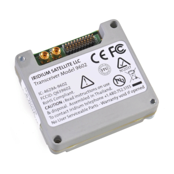
Page 10: Physical Specification
Subject to Change Without Notice Revision 4.0 2 Physical Specification For illustrative purposes a picture of the Iridium 9602 SBD Transceiver Module is shown in Figure 1. Figure 1 Iridium 9602 SBD Transceiver 2.1 Module Dimensions The overall dimensions of the 9602 module and its weight are summarized in Table 2 and represented... - Page 11 Iridium Communications Inc. Information Contained in this Guide 9602 SBD Transceiver Product Developers Guide is Subject to Change Without Notice Revision 4.0 Figure 2 General Assembly and Dimensions of the 9602 SBD Transceiver Module (Not to scale, dimensions in millimeters) This drawing shows some of the key dimensions within the 9602 specify the mechanical position of its connectors with respect to its mounting holes.
-
Page 12: Mechanical Dimensions - Motherboard Mounting
Iridium Communications Inc. Information Contained in this Guide 9602 SBD Transceiver Product Developers Guide is Subject to Change Without Notice Revision 4.0 2.2 Mechanical Dimensions – Motherboard Mounting The 9602 SBD Transceiver must be fitted within an enclosed host system. With appropriate external connections, the host system motherboard and host system enclosure can be designed to meet full transceiver regulatory tests. - Page 13 Iridium Communications Inc. Information Contained in this Guide 9602 SBD Transceiver Product Developers Guide is Subject to Change Without Notice Revision 4.0 Figure 4 Example host system motherboard footprint showing mounting position of 9602 (Not to scale. Dimensions in millimeters) Notes for Figure 4: Iridium Communications Inc.
- Page 14 Iridium Communications Inc. Information Contained in this Guide 9602 SBD Transceiver Product Developers Guide is Subject to Change Without Notice Revision 4.0 1. This example of a host system motherboard footprint is shown for illustrative purposes only. The host system may require a different PCB layout or mechanical arrangement.
-
Page 15: Environmental
Operating Temperature Range based on a duty-cycled usage model with 9602 sending one SBD message per hour and is otherwise turned off during the hour. Iridium has tested the 9602 per these temperature condition and partners venturing outside of these stated conditions need to ensure they have engineered a solution appropriate to the stated environmental conditions for the 9602. -
Page 16: Electrical Interfaces
Iridium Communications Inc. Information Contained in this Guide 9602 SBD Transceiver Product Developers Guide is Subject to Change Without Notice Revision 4.0 3 Electrical Interfaces The following subsections contain information for the electrical interfaces of the 9602 SBD Transceiver for the non-RF connections. -
Page 17: User Connector Pin Allocation
Iridium Communications Inc. Information Contained in this Guide 9602 SBD Transceiver Product Developers Guide is Subject to Change Without Notice Revision 4.0 3.1.5 User Connector Pin Allocation The user connector is a 2-row 20-way header. Individual pin assignments are shown in Table 7 and the limits for the digital signals are listed in Table 8. - Page 18 Iridium Communications Inc. Information Contained in this Guide 9602 SBD Transceiver Product Developers Guide is Subject to Change Without Notice Revision 4.0 Figure 5 provides a reference for the pin designation. This view is not to scale and not representative of the connector mechanical layout.
-
Page 19: Dc Power Interface
Iridium Communications Inc. Information Contained in this Guide 9602 SBD Transceiver Product Developers Guide is Subject to Change Without Notice Revision 4.0 3.2 DC Power Interface The DC power interface is comprised of the DC power inputs and a control signals as summarized in Table 7. -
Page 20: Power On/Off Control
Iridium Communications Inc. Information Contained in this Guide 9602 SBD Transceiver Product Developers Guide is Subject to Change Without Notice Revision 4.0 3.2.4 Power On/Off Control An external on/off input is provided on a pin of the User connector. The 9602 starts up when power is applied and the power on/off input is high. - Page 21 Iridium Communications Inc. Information Contained in this Guide 9602 SBD Transceiver Product Developers Guide is Subject to Change Without Notice Revision 4.0 Transmitter data burst (Typically 1.5A ) Receiver data burst (Typically 195mA) Background (Typically 40mA) Time (mS) Figure 6 Typical Supply Current Profile Iridium Communications Inc.
-
Page 22: Serial Data Interface
Network Available means only that the 9602 can successfully receive the Ring Channel, or, put more simply, it can see an Iridium satellite. Network Available is not a guarantee that a message can be successfully sent. The Network Available state is evaluated every time the Ring Channel is received or missed. -
Page 23: Rf Interface
Polarization RHCP VSWR (maximum operational) 1.5 : 1 Note: Existing qualified Iridium antennas may be used. (i.e. antennas designed for the 9601, 9522, 9522A Iridium Communications Inc. Distribution of Guide Restricted Proprietary & Confidential Information to Product Developers Only... -
Page 24: Gps Connector
9602 module has been turned off using its ON/OFF control signal. If the GPS port is not used it may be left un-terminated with no adverse effect. The GPS receiver must present 50 ohm impedance across the Iridium band or SBD performance could be degraded. -
Page 25: R F Interface Specifications
3dB. The total cable loss between the antenna and the modem includes losses in the motherboard. Implementation loss higher than this will affect the Iridium link performance and quality of service. Solutions with a loss higher than 3dB will not meet the requirements of Iridium Solution Certification. -
Page 26: At Command Set Description
9602 software releases, see the relevant software release notes, which are made available to authorized Iridium VARs and VAMs on the Iridium Developer Extranet. It is the responsibility of Product Developers to check compatibility of applications software with the AT Commands on all 9602s used for both development and commercial deployments.
Need help?
Do you have a question about the SBD9602 and is the answer not in the manual?
Questions and answers