
Related Manuals for RKI Instruments AirLink 7010


Summary of Contents for RKI Instruments AirLink 7010
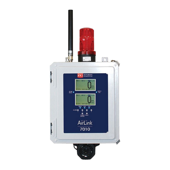
- Page 1 AirLink 7010 Gas Monitor Operator’s Manual Part Number: 71-0537 Revision: P2 Released: 7/13/21 www.rkiinstruments.com...
- Page 2 Product Warranty RKI Instruments, Inc. (Manufacturer) warrants its products to be free of defects in workmanship and materials—under normal use and service—for one year from the date of purchase from the manufacturer or from the product's authorized reseller. The manufacturer is not liable (under this warranty) if its testing and examination disclose that the alleged defect in the product does not exist or was caused by the purchaser's (or any third party's) misuse, neglect, or improper installation, testing or calibrations.
-
Page 3: Table Of Contents
Mounting the AirLink 7010 Gas Monitor ........ - Page 4 Register Map ..............46 4 • Product Warranty AirLink 7010 Gas Monitor Operator’s Manual...
-
Page 5: Chapter 1: Introduction
Once the threshold value of a relay is reached, the relay is activated. However, the AirLink 7010 screen will not lock on the channel with a triggered relay while the reading is below the Relay Set Point (the user must scroll through the channels to find the channel with a triggered relay). -
Page 6: About This Manual
About this Manual The AirLink 7010 Gas Monitor Operator’s Manual uses the following conventions for notes, cautions, and warnings: NOTE: Describes additional or critical information. CAUTION: Describes potential damage to equipment. WARNING: Describes potential danger that can result in injury or death. -
Page 7: Specifications
Specifications Table 1 lists specifications for the AirLink 7010. Table 1: AirLink 7010 Specifications Description Specification Input Power 110/240V ~ 12 - 35 V Current Draw 175 mA max at 24 VDC (monitor without sensor assemblies); 6.6 Watts max Operating Temperature -22°F to 158°F (-30°C to 70°C) -
Page 8: Chapter 2: Description
Chapter 2: Description Front Panel Figure 1: Front Panel 8 • Chapter 2: Description AirLink 7010 Gas Monitor Operator’s Manual... -
Page 9: Terminal Board
Terminal Board Figure 2: Terminal Board AirLink 7010 Gas Monitor Operator’s Manual Chapter 2: Description • 9... -
Page 10: Internal Components
Internal Components Note: Delta power supply only included with AC-powered version. Figure 3: Internal Components 10 • Chapter 2: Description AirLink 7010 Gas Monitor Operator’s Manual... -
Page 11: Chapter 3: Installation
2. Close and latch the housing door. 3. Prepare the selected mounting site as required to mount the AirLink 7010. It should be mounted at eye level (4 1/2 to 5 feet from the floor). Refer to Figure 4 for the outline and mounting dimensions. - Page 12 Ø .31 x .51 slot, 4X 27.84 18.63 20.49 12.19 900 M Hz Antenna 2.4 GHz Antenna Figure 4: Outline and Mounting Dimensions 12 • Chapter 3: Installation AirLink 7010 Gas Monitor Operator’s Manual...
-
Page 13: Wiring The Airlink 7010 Gas Monitor
CAUTION: The internal components can be static sensitive. Use caution when opening the enclosure and handling internal components. WARNING: Make all connections to the AirLink 7010 before you plug in or turn on the AC or DC power source. Before you make any wiring adjustments, always verify that all power sources are not live. - Page 14 10. Clamp down the enclosure latches. Connecting an AC Power Source NOTE: The AirLink 7010 is configured for AC or DC operation, depending on how it is ordered. If you are using DC power as the primary power source, go to the previous section, “Connecting a DC Power Source”.
- Page 15 Delta power supply terminals “L” (AC Load IN), “N” (AC Neutral IN), and “EG” (Chassis GND or Earth GND). This set of wires will be used to plug into an AC power outlet ONCE ALL WIRING CONFIGURATIONS ARE COMPLETE. AirLink 7010 Gas Monitor Operator’s Manual Chapter 3: Installation • 15...
- Page 16 Connect a ground wire from the AC power source to the power supply’s “EG” terminal. NOTE: If the AirLink 7010 was not ordered with any housing holes, at least one hole will have to be drilled to bring in AC power.
- Page 17 8. Plug the DB-9 connector into a PLC. Figure 7: Modbus Out Wiring 9. Close the Front Panel. 10. Screw in the thumb-screws. 11. Close the enclosure box. 12. Clamp down the enclosure latches. AirLink 7010 Gas Monitor Operator’s Manual Chapter 3: Installation • 17...
- Page 18 4. Locate the Fault Terminal Block on the terminal board. 5. Connect a positive (red) wire to the terminal labeled “+”. 6. Connect a negative (black) wire to the terminal labeled “-”. Figure 8: Fault Indicator Wiring 18 • Chapter 3: Installation AirLink 7010 Gas Monitor Operator’s Manual...
- Page 19 Connecting Sensors The AirLink 7010 allows up to 32 WireFree sensor assemblies or up to 28 WireFree sensor assemblies and 4 wired 4-20 mA type sensor assemblies to be monitored. 1. Open the enclosure box to expose the Front Panel.
- Page 20 Relay Wiring The AirLink 7010 has four relays. Each of the four relays may be setup as Normally Open (NO) or Normally Closed (NC). See page 42 for more explanation about relay actuation. NOTE: If installed, the strobe is factory wired to the Relay 1 terminals and the horn is factory wired to the Relay 2 terminals.
- Page 21 Figure 10: Relay Wiring AirLink 7010 Gas Monitor Operator’s Manual Chapter 3: Installation • 21...
-
Page 22: Chapter 4: Startup And Operation
CAUTION: The internal components can be static sensitive. Use caution when opening the enclosure and handling internal components. Once power is supplied to the AirLink 7010—by being plugged into an AC outlet or by being wired to a DC power supply—the display screen and LEDs will illuminate. - Page 23 Normal Operation The AirLink 7010 can monitor up to 32 WireFree sensor assemblies or up to 28 WireFree sensor assemblies and up to 4 wired sensor assemblies. When in Normal Operating Mode, configured channels are scanned through, 2 channels at a time, every 3 seconds.
-
Page 24: Holding Channels
A Fault condition is occurring on the monitor blue Normal Operating Mode 1. Press and release RESET/ESC to clear an alarm indication once the alarm condition has cleared. 24 • Chapter 4: Startup and Operation AirLink 7010 Gas Monitor Operator’s Manual... -
Page 25: Chapter 5: Setup Mode
Information. NOTE: Each channel must be set up individually. NOTE: To save any changes and exit Setup Mode at any time, press ESC. The AirLink 7010 automatically saves any changes and returns to Normal Operating Mode 15 minutes after the last button press. - Page 26 5. Wired/WireFree (for channels 29-32 only): Press ADD or SUB to change the channel type to Wired or WireFree. NOTE: Any sensors wired directly to the AirLink 7010 must be set up on channels 29-32. 6. Press MENU (Next). 26 • Chapter 5: Setup Mode...
- Page 27 R1234, R32, SF6, SiH4, B2H6, BF3. 8. Press MENU (Next). 9. Sensor Scale (wired only): Press ADD (increase) or SUB (decrease) to select a sensor scale (1- 65,000). 10. Press MENU (Next). AirLink 7010 Gas Monitor Operator’s Manual Chapter 5: Setup Mode • 27...
- Page 28 0 decimals: Scale greater than 100 (decimal screen does not appear in this case) 12. Press MENU (Next). 13. Radio Address (wirefree only): Press ADD (increase) or SUB (decrease) to set to radio address (1- 255). 14. Press MENU (Next). 28 • Chapter 5: Setup Mode AirLink 7010 Gas Monitor Operator’s Manual...
-
Page 29: Relay Settings
3. Relay Increasing/Decreasing: Press ADD or SUB to manipulate the relay's Increasing/Decreasing status. 4. Press MENU (next). 5. Relay Threshold: Press ADD (increase) or SUB (decrease) to manipulate the threshold value (1- 65,000). AirLink 7010 Gas Monitor Operator’s Manual Chapter 5: Setup Mode • 29... -
Page 30: View System Information
After the last channel is set, press MENU to view the system's information, including the: • Build Date (Example: 01/01/2011) • Serial # (Example: H00001) • Radio (type) • Radio error 30 • Chapter 5: Setup Mode AirLink 7010 Gas Monitor Operator’s Manual... -
Page 31: Exiting Setup Mode
1. Press ESC at any time to exit Setup Mode. 2. Close the enclosure box. 3. Clamp down the enclosure latches. NOTE: The AirLink 7010 automatically saves any changes and returns to Normal Operating Mode 15 minutes after the last button press. AirLink 7010 Gas Monitor Operator’s Manual... -
Page 32: Chapter 6: Advanced Configuration Menu
2. Cycle the unit's power (turn OFF, then ON). For instructions on how to cycle the unit's power, see page 22. 3. When the RKI Logo is shown on the Display Screen, press MENU. NOTE: The AirLink 7010 automatically saves any changes and returns to Normal Operating Mode 15 minutes after the last button press. Adjusting Contrast 1. -
Page 33: Restore Factory Default Settings
All relays set to “Auto Reset” / “Increasing” • Modbus Output Baud set at 9600 • Radio Timeout set to 10 minutes • Network ID set to 5 • Secondary Monitor AirLink 7010 Gas Monitor Operator’s Manual Chapter 6: Advanced Configuration Menu • 33... -
Page 34: Relay Setup
4. Fault Terminal Failsafe: Press ADD or SUB (Yes/No—as indicated on the display screen) to setup the Fault terminal as failsafe (or not failsafe). To leave the setting as it is, press MENU (Next). 34 • Chapter 6: Advanced Configuration Menu AirLink 7010 Gas Monitor Operator’s Manual... -
Page 35: Modbus Setup
3. Global Baud: Press ADD (increase) or SUB (decrease) to manipulate the global Baud setting to: 4800, 9600, or 19200. NOTE: Baud default is 9600. 4. Press MENU (Next). AirLink 7010 Gas Monitor Operator’s Manual Chapter 6: Advanced Configuration Menu • 35... -
Page 36: Wirefree Setup
NOTE: There can only be one Primary monitor on a network. All other monitors must be set up as Secondary monitors. If an AirLink 7010 is set as a Secondary monitor when there is no Primary monitor, the AirLink 7010 will go into a Fault 15 status. The POWER/STATUS LED will be green if the monitor becomes the Primary monitor;... -
Page 37: Exiting The Advanced Configuration Menu
1. Press ESC at any time to exit the Advanced Configuration Menu. 2. Close the enclosure box. 3. Clamp down the enclosure latches. NOTE: The AirLink 7010 automatically saves any changes and returns to Normal Operating Mode 15 minutes after the last button press. AirLink 7010 Gas Monitor Operator’s Manual... -
Page 38: Chapter 7: Maintenance
3. Starting with Relay 1, the relays will activate in 5-second intervals. 4. To return to Normal Operating Mode, release and press RESET/ESC. 5. Close the enclosure box. 6. Clamp down the enclosure latches. 38 • Chapter 7: Maintenance AirLink 7010 Gas Monitor Operator’s Manual... -
Page 39: Troubleshooting
Table 2 describes symptoms, probable causes, and recommended actions for the most common problems you may encounter with the AirLink 7010. NOTE: This troubleshooting guide describes AirLink 7010 problems only. See the detector head operator’s manuals for preventive maintenance procedures that apply to the detector heads installed on your AirLink 7010. - Page 40 Table 2: Troubleshooting the AirLink 7010 (Continued) Condition Probable Causes Recommended Action There are 2 sensor assemblies with the 1. Make sure all sensor assemblies same address trying to communicate with have unique addresses. the monitor. The monitor has not received a 1.
-
Page 41: Chapter 8: Parts List
Chapter 8: Parts List Table 3 lists the part numbers and descriptions for replacement parts and accessories offered for the AirLink 7010 Gas Monitor. Table 3: Parts List, AirLink 7010 Gas Monitor Part No. Description 18-0107RK Conduit hub (3/4 in.) 51-0040-RED Strobe/horn, 20 - 28 VDC, Cl. -
Page 42: Appendix A: Relay Operation
When using a Wet Contact Relay, power should run through the “COMM” terminal to the end equipment. Figure 13: “Dry” Contact Relay Configured as a “Wet” Contact 42 • Appendix A: Relay Operation AirLink 7010 Gas Monitor Operator’s Manual... - Page 43 The NC (normally closed) relay contacts are open during non-alarm operation and close when the appropriate alarm condition occurs. Figure 14: Relay Circuit Schematic AirLink 7010 Gas Monitor Operator’s Manual Appendix A: Relay Operation • 43...
- Page 44 (DMM), or current meter, may be used in conjunction with the controller and/or to test the 4-20 mA current loop signal. To measure the current, place the meter probes in line with the current loop. 44 • Appendix B: Introduction to 4-20 mA Current Loop Signals AirLink 7010 Gas Monitor Operator’s Manual...
-
Page 45: Appendix B: Rs-485 Modbus Output
Start Address: The first register the user would like to view (must be between 1-255) Length: Depends on the number of addresses the user would like to view Scan Rate:1000 ms Data Format: Hex, Decimal, Float AirLink 7010 Gas Monitor Operator’s Manual Appendix C: RS-485 Modbus Output • 45... -
Page 46: Register Map
Radio Address (1-255) Channel 32 Radio Address R/W 16 INTEGER Radio Address (1-255) Channel 1 Reading FLOAT Any valid sensor reading Channel 2 Reading FLOAT Any valid sensor reading 46 • Appendix C: RS-485 Modbus Output AirLink 7010 Gas Monitor Operator’s Manual... - Page 47 Channel 10 Mode ENUMERATION 0-7 See Mode Enumeration Below Channel 11 Mode ENUMERATION 0-7 See Mode Enumeration Below Channel 12 Mode ENUMERATION 0-7 See Mode Enumeration Below AirLink 7010 Gas Monitor Operator’s Manual Appendix C: RS-485 Modbus Output • 47...
- Page 48 Channel 20 Battery FLOAT Sensor Input Voltage( >= 0.0) Channel 21 Battery FLOAT Sensor Input Voltage( >= 0.0) Channel 22 Battery FLOAT Sensor Input Voltage( >= 0.0) 48 • Appendix C: RS-485 Modbus Output AirLink 7010 Gas Monitor Operator’s Manual...
- Page 49 -1-32768 Seconds, -1 = no transmissions. Staying 0 = timeout Channel 32 Sec Since Last Message INTEGER -1-32768 Seconds, -1 = no transmissions. Staying 0 = timeout AirLink 7010 Gas Monitor Operator’s Manual Appendix C: RS-485 Modbus Output • 49...
- Page 50 Channel 8 Gas Type ENUMERATION 0-127 See Gas Enumeration below Channel 9 Gas Type ENUMERATION 0-127 See Gas Enumeration below Channel 10 Gas Type ENUMERATION 0-127 See Gas Enumeration below 50 • Appendix C: RS-485 Modbus Output AirLink 7010 Gas Monitor Operator’s Manual...
- Page 51 Channel 18 Fault ENUMERATION 0-15 See Fault Enumeration below Channel 19 Fault ENUMERATION 0-15 See Fault Enumeration below Channel 20 Fault ENUMERATION 0-15 See Fault Enumeration below AirLink 7010 Gas Monitor Operator’s Manual Appendix C: RS-485 Modbus Output • 51...
- Page 52 R/W 16 ENUMERATION 0 – 1, 0 means off, 1 means on Channel 30 On/Off R/W 16 ENUMERATION 0 – 1, 0 means off, 1 means on 52 • Appendix C: RS-485 Modbus Output AirLink 7010 Gas Monitor Operator’s Manual...
- Page 53 ENUMERATION 0 - 1 ,0 means low, 1 means high Channel 8 Relay 1 High/Low R/W 16 ENUMERATION 0 - 1 ,0 means low, 1 means high AirLink 7010 Gas Monitor Operator’s Manual Appendix C: RS-485 Modbus Output • 53...
- Page 54 Any number 65000 or less and higher than 0 Channel 18 Relay 1 Set Point R/W 32 FLOAT Any number 65000 or less and higher than 0 54 • Appendix C: RS-485 Modbus Output AirLink 7010 Gas Monitor Operator’s Manual...
- Page 55 ENUMERATION 0 - 1 ,0 means unlatch, 1 means latch Channel 28 Relay 1 Latch/Unlatch R/W 16 ENUMERATION 0 - 1 ,0 means unlatch, 1 means latch AirLink 7010 Gas Monitor Operator’s Manual Appendix C: RS-485 Modbus Output • 55...
- Page 56 ENUMERATION 0 - 1 ,0 means low, 1 means high Channel 6 Relay 2 High/Low R/W 16 ENUMERATION 0 - 1 ,0 means low, 1 means high 56 • Appendix C: RS-485 Modbus Output AirLink 7010 Gas Monitor Operator’s Manual...
- Page 57 Any number 65000 or less and higher than 0 Channel 16 Relay 2 Set Point R/W 32 FLOAT Any number 65000 or less and higher than 0 AirLink 7010 Gas Monitor Operator’s Manual Appendix C: RS-485 Modbus Output • 57...
- Page 58 ENUMERATION 0 - 1 ,0 means unlatch, 1 means latch Channel 26 Relay 2 Latch/Unlatch R/W 16 ENUMERATION 0 - 1 ,0 means unlatch, 1 means latch 58 • Appendix C: RS-485 Modbus Output AirLink 7010 Gas Monitor Operator’s Manual...
- Page 59 ENUMERATION 0 - 1 ,0 means low, 1 means high Channel 4 Relay 3 High/Low R/W 16 ENUMERATION 0 - 1 ,0 means low, 1 means high AirLink 7010 Gas Monitor Operator’s Manual Appendix C: RS-485 Modbus Output • 59...
- Page 60 Any number 65000 or less and higher than 0 Channel 14 Relay 3 Set Point R/W 32 FLOAT Any number 65000 or less and higher than 0 60 • Appendix C: RS-485 Modbus Output AirLink 7010 Gas Monitor Operator’s Manual...
- Page 61 ENUMERATION 0 - 1 ,0 means unlatch, 1 means latch Channel 24 Relay 3 Latch/Unlatch R/W 16 ENUMERATION 0 - 1 ,0 means unlatch, 1 means latch AirLink 7010 Gas Monitor Operator’s Manual Appendix C: RS-485 Modbus Output • 61...
- Page 62 ENUMERATION 0 - 1 ,0 means low, 1 means high Channel 2 Relay 4 High/Low R/W 16 ENUMERATION 0 - 1 ,0 means low, 1 means high 62 • Appendix C: RS-485 Modbus Output AirLink 7010 Gas Monitor Operator’s Manual...
- Page 63 Any number 65000 or less and higher than 0 Channel 12 Relay 4 Set Point R/W 32 FLOAT Any number 65000 or less and higher than 0 AirLink 7010 Gas Monitor Operator’s Manual Appendix C: RS-485 Modbus Output • 63...
- Page 64 ENUMERATION 0 - 1 ,0 means unlatch, 1 means latch Channel 22 Relay 4 Latch/Unlatch R/W 16 ENUMERATION 0 - 1 ,0 means unlatch, 1 means latch 64 • Appendix C: RS-485 Modbus Output AirLink 7010 Gas Monitor Operator’s Manual...
- Page 65 Number of days since last nulled. (Added in Firmware 5.1.3) 1024 Channel 20 Time Since Last Nulled UINT Number of days since last nulled. (Added in Firmware 5.1.3) AirLink 7010 Gas Monitor Operator’s Manual Appendix C: RS-485 Modbus Output • 65...
- Page 66 Number of days since last Calibrated. (Added in Firmware 5.1.3) 1066 Channel 30 Time Since Last Calibrated R UINT Number of days since last Calibrated. (Added in Firmware 5.1.3) 66 • Appendix C: RS-485 Modbus Output AirLink 7010 Gas Monitor Operator’s Manual...
- Page 67 Channel 2 RSSI INTEGER 0-100% Receive Signal Strength 183B 6203 Channel 3 RSSI INTEGER 0-100% Receive Signal Strength 183C 6204 Channel 4 RSSI INTEGER 0-100% Receive Signal Strength AirLink 7010 Gas Monitor Operator’s Manual Appendix C: RS-485 Modbus Output • 67...
- Page 68 0 – 65535 270D 9997 Uptime Days UINT 0 – 65535 270E 9998 Uptime Hours UINT 0 – 65535 270F 9999 Uptime Minutes UINT 0 – 65535 68 • Appendix C: RS-485 Modbus Output AirLink 7010 Gas Monitor Operator’s Manual...
- Page 69 14 No Primary Monitor at Sensor Head 15 Monitor Fault GAS TYPE NUM 0 H2S 1 SO2 2 O2 3 CO 4 CL2 5 CO2 6 LEL AirLink 7010 Gas Monitor Operator’s Manual Appendix C: RS-485 Modbus Output • 69...
- Page 70 28 EtO (Firmware 5.1.3) 29 CH3SH (Firmware 5.1.3) 30 AsH3 (Firmware 5.1.3) 31 R410A (Firmware 5.1.3) 32 R1234YF (Firmware 5.1.3) 33 R32 (Firmware 5.1.3) 34..N Future Gases 70 • Appendix C: RS-485 Modbus Output AirLink 7010 Gas Monitor Operator’s Manual...
Need help?
Do you have a question about the AirLink 7010 and is the answer not in the manual?
Questions and answers