
Related Manuals for Eco-Eye Smart 3pA Series

Summary of Contents for Eco-Eye Smart 3pA Series
- Page 1 Eco-Eye Smart Commercial Smart 3pA 3 phase monitoring and recording Set-up and Operating Instructions Efficient technology for today’s world Smart 3pA Page 1...
-
Page 2: Table Of Contents
Contents 1. Introduction 1.1 Package contents 1.2 Important notes 2. Installing Eco-eye Smart Commercial 2.1 Overview 2.2 Find your Electricity supply 2.3 Attaching the sensors 2.4 Connecting to the transmitter 2.5 Powering the display 2.6 Is it working 3. Using the Display 3.1 Real-time or Predicted Mode... -
Page 3: Introduction
The Smart 3pA monitors are sophisticated devices designed especially for commercial 3 phase monitoring . This monitor combines the simplicity of the Eco-eye brand but has some clever features which are useful to anyone with commercial premises which they would like to monitor in detail and get a better... -
Page 4: Overview
2.1. Overview Eco Eye Smart has three basic components – The sensors, the transmitter and the Wireless display. The sensors clip round the three live cables under your meter or fuse box (as illustrated above 1,2,3) and monitors the total current passing through them. This is a simple job and involves no cutting or disturbing of any wiring or the need for a qualified electrician unless you feel uncomfortable removing electrical trunking to get access to cables. - Page 5 2.2 Locating your meter Once you have located your electricity meter it should look something like the one listed below. You will need to connect the 3 sensors round the 3 live cables coming into that meter. The sensors simply clip round each of the coloured cables – Red, Yellow and blue. (The black is the neutral) In the picture below there are 2 cables for each phase, generally the left hand one is from the grid and the right one is the supply to the property.
-
Page 6: Attaching The Sensors
2.3 Attaching the sensors The Sensor is in two parts and one is clipped around each of the three live cables. Press the side clips of the sensor to separate the two parts. Place it around the cable. Click shut- do not force the sensor shut around a cable that is too big as this could damage the sensors inner core. - Page 7 2.4 Connecting the sensors to the transmitter lug the three sensor cables into the transmitter on the underside of the transmitter. Remembering which cable is plugged into each socket. (I.e. sensor 1 = Red etc.) Press the release catch to remove the wall plate and use a double sided self-adhesive sticky pad or screw (not supplied) to affix in a convenient position close to the cables being monitored.
-
Page 8: Is It Working
2.5 Power up the display unit Remove the battery cover from the display unit (and the memory card if installed) and insert 2 x C Cell batteries, ensuring they are in the right way round. Then replace the battery cover After a short power up routine you will need to input some basic information. -
Page 9: Using The Display
● Phase 3 3.1 Real-time or Predicted Mode Eco-eye Smart normally shows how much electricity you are using right now. This is real-time or predicted mode. You will see the arrow and P (see left) when you are in predicted mode. -
Page 10: Checking The Signal Strength
4.1 Changing the Voltage on the display The Kilowatt value is calculated from the amps being monitored by reference to a voltage stored on the monitor. To change the stored voltage value: Use the round green button to the KW display press and hold the rectangular green button 3 seconds and Volts “SET”... -
Page 11: Guide To The Screen
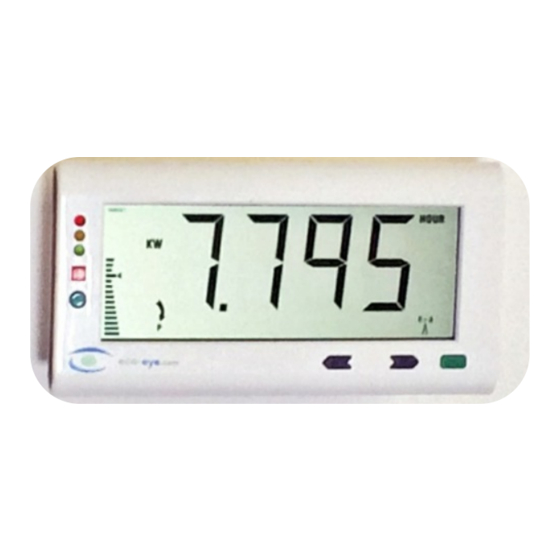
5. Guide to the screen A. The Big Number K. See Trax manual B. Modes L. See Trax manual C.Time Periods M. See Trax manual D.Target graph N. Big number is accumulated E. Real-time (predicted) display O. Big number is target % F. -
Page 12: Important - Safety And Care
Before attempting to fit Eco-eye, ensure you have read and understood the fitting instructions fully. Do not attempt to carry out any repairs to Eco-eye. Contact your retailer or Eco-eye direct if problems occur. Use of Eco-eye near moisture or liquids; or in extreme temperatures can cause malfunction and damage.
Need help?
Do you have a question about the Smart 3pA Series and is the answer not in the manual?
Questions and answers