IBM Power System LC921 Quick Install Manual
Hide thumbs
Also See for Power System LC921:
- Quick install manual (16 pages) ,
- Quick install manual (20 pages) ,
- Manual (126 pages)
Advertisement
Quick Links
IBM
Power System LC921
(9006-12P) Quick Install
IBM
Guide
®
®
IBM
Power
System LC921 (9006-12P) Quick Install Guide
The IBM Knowledge Center is available online from: http://www.ibm.com/support/knowledgecenter/
POWER9/p9hdx/9006_12p_landing.htm.
v Read all precautions and instructions before you start working on key parts.
v Use normal electrostatic discharge (ESD) procedures when working on the system and parts. IBM
recommends wearing gloves and an anti-static wrist strap to avoid possible damage to the equipment.
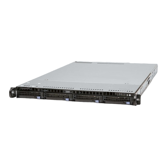
9006-12P parts
Figure 1. Rack final assembly
Advertisement

Related Manuals for IBM Power System LC921


Summary of Contents for IBM Power System LC921
- Page 1 Read all precautions and instructions before you start working on key parts. v Use normal electrostatic discharge (ESD) procedures when working on the system and parts. IBM recommends wearing gloves and an anti-static wrist strap to avoid possible damage to the equipment.
- Page 2 Figure 2. System parts...
-
Page 3: Rear Ports
Figure 3. Additional system parts Rear ports... -
Page 4: Installing And Removing
Figure 4. Rear ports Table 1. Input and output ports Identifier Description USB 2.0 used for keyboard and mouse. Certain USB drives might be too wide to fit properly into the USB ports on the rear of the system. Test the fit of your USB drive before proceeding. - Page 5 Figure 7. Removing a front drive Figure 8. Removing the 3.5-inch drive from the tray Figure 9. Removing a DOM Figure 10. Removing the disk drive backplane and screws...
- Page 6 Figure 11. Removing the fan holder Figure 12. Removing a fan Figure 14. Aligning the fan holder Figure 13. Disconnecting the fan cable...
- Page 7 Figure 16. Two-processor memory plugging sequence Figure 15. Removing the memory DIMM Figure 17. 9006-12P PCIe adapter positions Figure 18. Removing the PCIe riser...
- Page 8 Figure 20. Removing a PCIe adapter from position 3 of the riser Figure 19. Removing the UIO Network screws Figure 21. Removing a PCIe adapter from position 2 or 3 of the riser Figure 22. Removing the PCIe riser cards from the PCIe adapter cage...
- Page 9 Figure 23. Removing the processor socket screws from the bottom of the chassis Figure 24. Screw locations Figure 25. Lifting out the system backplane Figure 26. Loosening the load arm screw of the heat sink...
- Page 10 Figure 27. Removing the heat sink Figure 28. Locking the system processor module into the tool Figure 29. Installing the system processor module Figure 30. Removing the system processor module tool...
- Page 11 Figure 34. Removing the TPM card Figure 33. Removing the time-of-day battery ™ ™ This May 17, 2018 edition applies to IBM Power Systems servers that contain the POWER9 processor and to all associated models. © Copyright IBM Corporation 2018.
Need help?
Do you have a question about the Power System LC921 and is the answer not in the manual?
Questions and answers