
Related Manuals for Pilz PNOZ ms2p HTL


Summary of Contents for Pilz PNOZ ms2p HTL
- Page 1 PNOZ ms2p HTL Configurable safety systems PNOZmulti Operating Manual-1001401-EN-04...
- Page 2 Preface This document is a translation of the original document. All rights to this documentation are reserved by Pilz GmbH & Co. KG. Copies may be made for internal purposes. Suggestions and comments for improving this documentation will be gratefully received.
-
Page 3: Table Of Contents
Connect incremental encoder to the speed monitor via an adapter Connection of proximity switches and incremental encoder 6.5.1 Proximity switch and incremental encoder on various axes 6.5.2 Proximity switch and incremental encoder on one axis Operating Manual PNOZ ms2p HTL 1001401-EN-04... - Page 4 Connection of an incremental encoder and proximity switch on an axis Section 7 Operation LED indicators Signal statuses Faults - malfunctions Section 8 Technical details Safety characteristic data Section 9 Order reference Product Accessories Section 10 Application Examples Operating Manual PNOZ ms2p HTL 1001401-EN-04...
-
Page 5: Operating Manual Pnoz Ms2P Htl
Introduction Introduction Validity of documentation This documentation is valid for the product PNOZ ms2p HTL. It is valid until new document- ation is published. This operating manual explains the function and operation, describes the installation and provides guidelines on how to connect the product. - Page 6 Introduction INFORMATION This gives advice on applications and provides information on special fea- tures. Operating Manual PNOZ ms2p HTL 1001401-EN-04...
-
Page 7: Overview Scope
Scope Expansion module PNOZ ms2p HTL Jumper Unit features Using the product PNOZ ms2p HTL: Speed monitor for connection to a base unit from the configurable control system PNOZmulti The product has the following features: Monitoring of 2 independent axes Connection per axis –... -
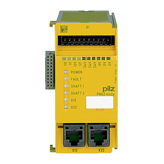
Page 8: Front View
X22: – female connector for the connection of an incremental encoder at axis 2 LEDs: – POWER – FAULT – SHAFT 1 – SHAFT 2 – – Operating Manual PNOZ ms2p HTL 1001401-EN-04... -
Page 9: Safety
For applications in accordance with PL e and SIL CL 3, the "Overspeed" output must be integrated into the safety function in every operating mode and evaluated so that a shutdown occurs if the output switches to a safe condition ("Overspeed" output = "0"). Operating Manual PNOZ ms2p HTL 1001401-EN-04... -
Page 10: System Requirements
System requirements Please refer to the "Product Modifications PNOZmulti" document in the "Version overview" section for details of which versions of the base unit and PNOZmulti Configurator can be used for this product. Operating Manual PNOZ ms2p HTL 1001401-EN-04... -
Page 11: Safety Regulations
In safety-related applications, please comply with the mission time T in the safety-re- lated characteristic data. When decommissioning, please comply with local regulations regarding the disposal of electronic devices (e.g. Electrical and Electronic Equipment Act). Operating Manual PNOZ ms2p HTL 1001401-EN-04... -
Page 12: For Your Safety
Do not open the housing or make any unauthorised modifications. Please make sure you shut down the supply voltage when performing maintenance work (e.g. exchanging contactors). Operating Manual PNOZ ms2p HTL 1001401-EN-04... -
Page 13: Function Description
Incremental encoders and/or proximity detectors can be used to record the values. The configuration of the speed monitor is described in detail in the PNOZmulti Configur- ator's online help. Block diagram RJ45 RJ45 Operating Manual PNOZ ms2p HTL 1001401-EN-04... -
Page 14: Input Device Types
Requirements of the incremental encoders Only incremental encoders with a differential output of the following type are permitted – HTL (12 V – 30 V) Please note the values stated in the technical details Operating Manual PNOZ ms2p HTL 1001401-EN-04... -
Page 15: Adapter For Incremental Encoders
The adapter records the data between the encoder and drive and makes it available to the PNOZ ms2p HTL via the RJ45 socket. Pilz supplies complete adapters as well as ready-made cable with RJ45 connector, which can be used when making your own adapter. The range of products in this area is con- stantly being expanded. -
Page 16: Installation
Damage due to electrostatic discharge! Electrostatic discharge can damage components. Ensure against discharge before touching the product, e.g. by touching an earthed, conductive sur- face or by wearing an earthed armband. Dimensions 94 (3.70") (1.77") Operating Manual PNOZ ms2p HTL 1001401-EN-04... -
Page 17: Connecting The Base Unit And Expansion Modules
Please refer to the document "PNOZmulti System Expansion" for details of the number of modules that can be connected to the base unit and the module types. Operating Manual PNOZ ms2p HTL 1001401-EN-04... -
Page 18: Commissioning
1 incremental encoder 2 proximity switches 1 incremental encoder and 1 proximity switch Incremental encoder Proximity switch Connection axis 1 I10, I11, 0 V I10, 0 V Connection axis 2 I20, I21, 0 V I20, 0 V Operating Manual PNOZ ms2p HTL 1001401-EN-04... -
Page 19: Pin Assignment Of Rj45 Socket
The proximity switch must always be connected to a 0 V terminal of the speed monitor. The 0 V terminals are connected internally. Connect proximity switch to 24 VDC of the power supply or the speed monitor (the 24 V terminals of the speed monitor are connected internally) Operating Manual PNOZ ms2p HTL 1001401-EN-04... -
Page 20: Connection Of The Incremental Encoder
Supply voltage (12 V – 30 V) to incremental encoder only. HTL signals may not be fitted with a terminating resistor. Operating Manual PNOZ ms2p HTL 1001401-EN-04... - Page 21 Adapter Incremental Drive 24 V 24 V DC encoder Speed monitor Fig.: Connection via adapter and drive Adapter Incremental 24 V 24 V DC encoder Speed monitor Fig.: Connection via adapter Operating Manual PNOZ ms2p HTL 1001401-EN-04...
- Page 22 Proximity switch and incremental encoder on various axes Axis 1: Proximity switch at I10, I11 incremental encoder at X12 Axis 2: Proximity switch at I20, I21 incremental encoder at X22 Fig.: Proximity switch and incremental encoder on various axes Operating Manual PNOZ ms2p HTL 1001401-EN-04...
- Page 23 Proximity switch at I10 (I11 is unused) Incremental encoder at X12 Axis 2: Proximity switch at I20 (I21 is unused) Incremental encoder at X22 Axis 1 Axis 1 Fig.: Proximity switch and incremental encoder on one axis Operating Manual PNOZ ms2p HTL 1001401-EN-04...
-
Page 24: Connection Examples
6.6.1 Connection of 2 proximity switches and an incremental encoder Description 2 proximity switches, pnp-switching 1 incremental encoder Speed monitor Incremental Encoder Drive PNOZ msi15p Fig.: Connection of 2 proximity switches, pnp-switching, one incremental encoder Operating Manual PNOZ ms2p HTL 1001401-EN-04... -
Page 25: Connection Of 4 Proximity Switches
Connection of 4 proximity switches Description 4 proximity switches, pnp-switching Connection through 24 V terminals and 0 V Speed monitor Fig.: Connection of 4 proximity switches, pnp-switching, connection through 24 V terminals and 0 V Operating Manual PNOZ ms2p HTL 1001401-EN-04... - Page 26 1 proximity switch, pnp-switching 1 incremental encoder Incremental encoder and proximity switch on one axis Speed monitor Incremental encoder Drive PNOZ msi15p Fig.: Connection of an incremental encoder and proximity switch, pnp-switching, on an axis Operating Manual PNOZ ms2p HTL 1001401-EN-04...
-
Page 27: Operation
The LEDs “POWER”, “DIAG”, “FAULT”, “IFAULT” and “OFAULT” will light up on the base unit. The PNOZmulti safety system is ready for operation when the "POWER" and "RUN" LEDs on the base unit and the "READY" LED on the PNOZ ms2p HTL are lit continuously. LED indicators Legend... -
Page 28: Signal Statuses
Monitoring the direction of rotation: If an internal error occurs or there is an error due to a defective incremental encoder ("FAULT" LED illuminates or flashes), an incorrect direction of rotation may be signalled for approx. 500 ms. Operating Manual PNOZ ms2p HTL 1001401-EN-04... -
Page 29: Technical Details
20 ms Reaction time f>100 Hz: Configurable switch-off delay + switch- off delay of base unit 10 ms f<100 Hz: Configurable switch-off delay + switch- off delay of base unit 10 ms + 1/f Operating Manual PNOZ ms2p HTL 1001401-EN-04... - Page 30 2 core with the same cross section, flexible without 0,25 - 0,75 mm², 24 - 20 AWG crimp connectors or with TWIN crimp connectors Torque setting with screw terminals 0,25 Nm Stripping length with screw terminals 7 mm Operating Manual PNOZ ms2p HTL 1001401-EN-04...
-
Page 31: Safety Characteristic Data
A safety function's SIL/PL values are not identical to the SIL/PL values of the units that are used and may be different. We recommend that you use the PAScal software tool to calculate the safety function's SIL/PL values. Operating Manual PNOZ ms2p HTL 1001401-EN-04... -
Page 32: Order Reference
PNOZmulti bus terminator Terminator 779 110 KOP-XE Jumper 774 639 Connection terminals Product type Features Order no. Set spring terminals 1 set of spring-loaded terminals 783 800 Set screw terminals 1 set of screw terminals 793 800 Operating Manual PNOZ ms2p HTL 1001401-EN-04... -
Page 33: Application Examples
If the "Overspeed" output (see red marking) = "0", either the maximum permitted speed has been exceeded or the speed monitor has recognised a fault. "Overspeed" output = "0" must lead to the shutdown of the relevant axis. Operating Manual PNOZ ms2p HTL 1001401-EN-04... - Page 34 If the "Overspeed" output (see red marking) = "0", either the maximum permitted speed has been exceeded or the speed monitor has recognised a fault. "Overspeed" output = "0" must lead to the shutdown of the relevant axis, irrespective of whether the "reduced speed" operating mode is active. Operating Manual PNOZ ms2p HTL 1001401-EN-04...
- Page 35 Front cover Support Technical support is available from Pilz round the clock. Americas Australia Scandinavia Brazil +61 3 95600621 +45 74436332 +55 11 97569-2804 Spain Canada Europe +34 938497433 +1 888-315-PILZ (315-7459) Austria Switzerland +41 62 88979-30 Mexico +43 1 7986263-0...
Need help?
Do you have a question about the PNOZ ms2p HTL and is the answer not in the manual?
Questions and answers