
Related Manuals for National Instruments NI 9485


Summary of Contents for National Instruments NI 9485
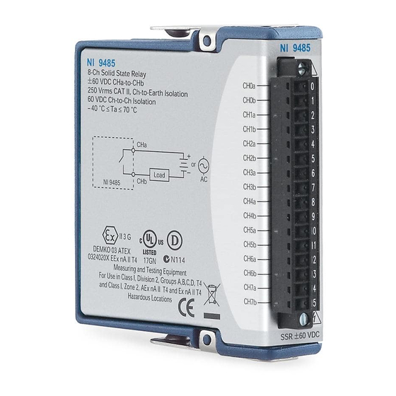
- Page 1 GETTING STARTED GUIDE NI 9485 8-Channel Solid-State Relay (SSR) Digital Output Module...
-
Page 2: Safety Guidelines
This document explains how to connect to the NI 9485. Before you begin, complete the software and Note hardware installation procedures in your chassis documentation. The guidelines in this document are specific to Note the NI 9485. The other components in the system might not meet the same safety ratings. -
Page 3: Safety Guidelines For Hazardous Voltages
You must use the NI 9939 connector backshell kit to ensure that the terminals are not accessible. NI 9485 Getting Started Guide | © National Instruments | 3... -
Page 4: Safety Voltages
1,000 Vrms, verified by a 5 s dielectric withstand test Channel-to-earth ground (up to 2,000 m) Continuous 250 Vrms, Measurement Category II Withstand 2,300 Vrms, verified by a 5 s dielectric withstand test 4 | ni.com | NI 9485 Getting Started Guide... - Page 5 Measurement Categories II, III, or IV. Measurement Categories CAT I and CAT O are Note equivalent. These test and measurement circuits are not intended for direct connection to the MAINS building NI 9485 Getting Started Guide | © National Instruments | 5...
-
Page 6: Safety Guidelines For Hazardous Locations
IV. Safety Guidelines for Hazardous Locations The NI 9485 is suitable for use in Class I, Division 2, Groups A, B, C, D, T4 hazardous locations; Class I, Zone 2, AEx nA IIC T4 and Ex nA IIC T4 hazardous locations; and nonhazardous locations only. - Page 7 Special Conditions for Hazardous Locations Use in Europe and Internationally The NI 9485 has been evaluated as Ex nA IIC T4 Gc equipment under DEMKO Certificate No. 03 ATEX 0324020X and is IECEx 14.0089X certified. Each NI 9485 is marked...
-
Page 8: Electromagnetic Compatibility Guidelines
-40 °C ≤ Ta ≤ 70 °C. If you are using the NI 9485 in Gas Group IIC hazardous locations, you must use the device in an NI chassis that has been evaluated as Ex nC IIC T4, Ex IIC T4, Ex nA IIC T4, or Ex nL IIC T4 equipment. -
Page 9: Special Conditions For Marine Applications
(shipboard) applications. To verify Lloyd’s Register certification for a product, visit ni.com/certification and search for the LR certificate, or look for the Lloyd’s Register mark on the product. NI 9485 Getting Started Guide | © National Instruments | 9... -
Page 10: Preparing The Environment
EMC performance is attained. Preparing the Environment Ensure that the environment in which you are using the NI 9485 meets the following specifications. Operating temperature -40 °C to 70 °C... - Page 11 Refer to the device datasheet on ni.com/manuals Note for complete specifications. Connecting the NI 9485 The NI 9485 has a 16-terminal, detachable screw-terminal connector. NI 9485 Getting Started Guide | © National Instruments | 11...
-
Page 12: Connecting Loads
Figure 1. NI 9485 Pinout CH0a CH0b CH1a CH1b CH2a CH2b CH3a CH3b CH4a CH4b CH5a CH5b CH6a CH6b CH7a CH7b Connecting Loads You can connect loads to the NI 9485. 12 | ni.com | NI 9485 Getting Started Guide... -
Page 13: Protecting Inductive Loads
Protecting Inductive Loads When you connect inductive loads to the NI 9485 SSR outputs, a large counter-electromotive force may occur at switching time as a result of the energy stored in the inductive load. These flyback voltages can damage the relay outputs and/or the external power supply. - Page 14 For AC loads—Install a metal oxide varistor (MOV) rated for 30 Vrms or slightly higher. Figure 3. Contact Protection for DC Inductive Loads Flyback Diode for DC Inductive Loads Inductive – Load NI 9485 14 | ni.com | NI 9485 Getting Started Guide...
-
Page 15: High-Vibration Application Connections
NI 9485: • Use ferrules to terminate wires to the detachable connector. • Use the NI 9939 backshell kit. NI 9485 Getting Started Guide | © National Instruments | 15... -
Page 16: Where To Go Next
NI 9485 Datasheet NI 9485 Datasheet NI-RIO Help NI-DAQmx Help LabVIEW FPGA Help LabVIEW Help RELATED INFORMATION C Series Documentation Services & Resources ni.com/services ni.com/info cseriesdoc Located at ni.com/manuals Installs with the software 16 | ni.com | NI 9485 Getting Started Guide... -
Page 17: Worldwide Support And Services
You can obtain the DoC for your product by visiting ni.com/certification. If your product supports calibration, you can obtain the calibration certificate for your product at ni.com/calibration. NI 9485 Getting Started Guide | © National Instruments | 17... - Page 18 Refer to the NI Trademarks and Logo Guidelines at for information on ni.com/trademarks National Instruments trademarks. Other product and company names mentioned herein are trademarks or trade names of their respective companies. For patents covering National Instruments products/technology, refer to the appropriate location: Help»Patents in your software, file on your media, or the National Instruments Patent Notice at patents.txt...
Need help?
Do you have a question about the NI 9485 and is the answer not in the manual?
Questions and answers