Table of Contents
Advertisement
Advertisement
Table of Contents

Subscribe to Our Youtube Channel
Related Manuals for SPARLING Irrigation FM314


Summary of Contents for SPARLING Irrigation FM314
- Page 1 Issue Date: .ebruary 1999 .M314/.T194...
- Page 2 SECTION 1.0 on page 1 concerning verifying equipment and operation, installation instructions and notes and wiring instructions. SPARLING INSTRUMENTS, INC. 4097 N. Temple City Blvd. El Monte, CA 91731 Ph (626) 444-0571 Fx (626) 452-0723 email: sales@sparlinginstruments.com Internet: http://www.sparlinginstruments.com Copyright© 1999 Sparling Instruments, Inc. All rights reserved.
-
Page 3: Table Of Contents
TABLE OF CONTENTS Page Page Section 1 - Unpacking & Inspection .....1 Figures 1.1 Receiving & Inspection ........1 Meter Operation ........... 1 1.2 Storage ............1 Installation Considerations ......3 1.3 Operation ............1 Tube mounting ..........4 Template for 4"-12" Meters ......4 1.4 Specifications .......... -
Page 5: Section 1 - Unpacking & Inspection
(626) 444-0571 you will then be advised of the measures to take. If you find items are missing from your shipment, contact the Sparling Customer Service Depart- ment immediately, at (626) 444-0571. They will verify the order and trace any missing item for you. -
Page 6: Specifications
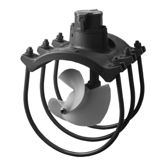
FM 314 ±2.0% of flow Specifications 32°. to 100°. -40°. to 175°. Saddle .......... Cast Iron (2" - 12") / Cast Aluminum (14") Propeller ..................Polyethylene Gearbox ....................Bronze Mechanical Parts ..............Stainless Steel Coatings ............... Grey water base paint Mounting .............. -
Page 7: Section 2 - Pre-Installation
Process Fluid The .M314 MainLine Electronic Propeller Meter is designed to operate with relatively clean process water. The percentage of solids should not exceed 0.5%. While the propeller shape is designed to shed debris Pre- and the propeller material is durable and somewhat pliable, large solid objects in the flowing stream could damage or become entangled in the propeller, causing inaccuracies or malfunction. -
Page 8: Mounting Low Pressure Line Meter
3.2 Mounting The Low Pressure Line Meter Meterheads are available with either a plain end tube or as a meterhead only which is strapped onto existing process pipe. Installation cont'd. Figure 3.2 Tube Mounting a. Be sure to read Section 3.1 Site Selection Criteria prior to installing your meter. b. -
Page 9: With Customers Existing Pipe - 14
c. Cut or burn a full opening in the pipe so there will be no projec- tions of the pipe beyond the straight inside edge of the hole. Smooth the pipe around the opening to make a good Installation surface for the saddle. cont'd. -
Page 10: Section 4 - Flow Rates & Dimensions
Maximum flow ranges can be safely exceeded by 50% when used intermittently (10-15% of the time). Your Sparling meter utilizes specially designed propellers and bearings matched to your flow range to insure long life. Flow Rates & Dimensions TABLE 2 - .LOW & DIMENSIONS .low Range... -
Page 11: Section 5 - Preventative Maintenance
Preventative Maintenance Low pressure line meters with ball bearings (low flow range) should be greased every 90 days of actual operation time with Lubriplate #105. Meters with fluted rubber bearings (standard flow range) and don't need to be lubricated as water provides their lubrication. Meter Maintenance Remove the meter from the line once each year and inspect the propeller shaft bearings, propeller,... -
Page 12: Disassembly & Repair
5.2 Disassembly & Repair 5.2.1 Grip the propeller and remove the propeller nut. Slip the propeller off by tapping it lightly Meter and remove the propeller shaft key (a). Maintenance 5.2.2 Remove the propeller shaft plug assembly and drive the propeller shaft out the rear of the gear box by tapping at the end of the propeller shaft with a rubber mallet or a piece of wood to pro- tect the shaft (b). -
Page 13: Section 6 - Preventative Maintenance Of Totalizer
Preventative Maintenance — Inspection of Totalizer The ideal time to inspect the totalizer is when you are changing the battery. Totalizer Open meter cover and check for condensation on inside of glass. Spin propeller and make Maintenance sure that the register advances properly. Remove screws holding the totalizer on the meterhead. Examine the battery contacts for signs of moisture intrusion. -
Page 14: Scaled Pulse Output
Integral Mount 4-20mA & Scaled Pulse Output (optional) Figure 7.1 4-20 mA & Scaled Pulse Output Remote Mount 4-20mA & Totalizer Output & Power to Unit Figure 7.2 4-20 mA & Scaled Pulse Output - Remote Mount Page 10 MainLine... -
Page 15: Orward/Reverse 4-20Ma
Forward & Reverse Totalization Reverse 4-20mA & Totalizer Output Forward 4-20mA & Totalizer Output Figure 7.2 4-20 mA & Scaled Pulse Output - Forward & Reverse IDS 314/194 Page 11... -
Page 16: Section 8 - Programming Of Electronic Totalizer
Programming 8.1 Preliminary Calculations of Electronic Totalizer Before programming your meter you will need to determine: Model 703 1) The Totalizer Scaling .actor and 2) The Rate Scaling .actor Programmer Optional These factors are not the same, but are both calculated using the meter's K (calibration) factor. The meter K is located on the flowmeter calibration sheet originally shipped with your meter. -
Page 17: Connect Programmer
(K/E) Programming K = Propeller Meter Calibration .actor (pulses/gallon) of Electronic E (GPM) = Desired Indication from table 4 below = 60 Totalizer Example: Meter K = 2.236 pulses/gallon Desired Engineering Unit = GPM (from Table 2 below) Rate Scaling .actor (GPM) K/E = 2.236 / 60 = 0.0373 .0373 pulses equals 1 gallon per minute K = Propeller Meter Calibration .actor (pulses/gallon) E = Engineering Unit Conversion .actor (from table below) -
Page 18: Programming Mode
8.3 Programming Mode Programming Press PROGRAM button on the programmer for 5-10 seconds. This activates the programming mode. The display will appear of Electronic as shown in .igure #8.2. The least significant digit will flash on Totalizer and off. cont'd. Enter the you calculated per the formu- Figure 8.2... -
Page 19: Reset Totalizer
8.4 Reset Totalizer - Figure 8.11 Programming of Electronic Totalizer CAUTION cont'd. 8.5 Programming Analog Rate Output (optional) Press PROGRAM Button and display screen as shown in .ig- ure #8.12 will appear. Enter , which for standard analog output is 0. The range is from 00000 to 99999 Using Vertical and Horizontal buttons program 00000. - Page 20 Sparling Instruments, Inc. Sparling Instruments, Inc. 4097 N. Temple City Blvd. • El Monte, CA 91731 • Ph (626) 444-0571 • Fax (626) 452-0723 Website: www.sparlinginstruments.com Email: sales@sparlinginstruments.com IDS 314 2/99 Copyright 1999 by Sparling Instruments, Inc. All rights reserved.
Need help?
Do you have a question about the Irrigation FM314 and is the answer not in the manual?
Questions and answers