
Related Manuals for Volpi Tecno Energia PAGURO 4 SY


Summary of Contents for Volpi Tecno Energia PAGURO 4 SY
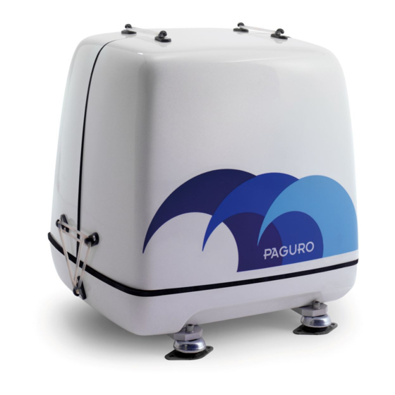
- Page 1 Web Site: www.volpitecno.com - E-mail: info@volpitecno.com MANUALE ISTRUZIONI OWNERS MANUAL PAGURO 4 SY...
- Page 2 142607201741...
- Page 3 Non c’è quindi bisogno di sprecare rilevanti spazi per l’installazione a bordo ed anche se l’ubicazione scelta non é centrale, il peso contenuto del PAGURO non influenzerà l’assetto della Vostra imbarcazione. CARATTERISTICHE TECNICHE E PRESTAZIONI PAGURO 4 SY Costruttore del motore YANMAR ITALY S.P.A. Modello motore...
- Page 4 INSTALLAZIONE Nell’installare il generatore PAGURO, prestate particolare attenzione alle seguenti informazioni: NORME Seguire con molta attenzione le norme di sicurezza di base, quando si installa il generatore PAGURO. VALVOLA ANTISIFONE: Se il generatore viene installato sotto o in prossimità della linea di galleggiamento (prendere come riferimento gli antivibranti esterni)- considerando anche l’imbarcazione in navigazione - è...
- Page 5 DOVE INSTALLARE IL VOSTRO PAGURO Bisogna prevedere uno spazio sufficiente intorno all’unità per le seguenti operazioni: Per il corretto ricambio dell’aria. Attorno al PAGURO sono consigliabili le distanze minime indicate di seguito; ovviamente l’ambiente dovrà essere ventilato naturalmente con più di un’apertura verso l’esterno. Per fissare il PAGURO a bordo.
- Page 6 DIMENSIONI: Un ulteriore attenuazione delle vibrazioni trasmesse all'imbarcazione e conseguentemente un ulteriore abbattimento del livello sonoro può essere ottenuto installando sotto il generatore una piattaforma di legno, a sua volta appoggiata su supporti antivibranti soffici. Tale piattaforma deve avere uno spessore di almeno di 30 mm allo scopo di avere un peso proprio superiore ai 10 Kg, comportandosi, quindi, come una massa in opposizione alle vibrazione indotte dal motore.
- Page 7 COLLEGAMENTI ESTERNI Deve essere rispettato il valore indicato dei diametri interni dei tubi per evitare allentamenti e perdite; è da mantenere anche il valore dei diametri esterni, poiché la loro corretta dimensione impedisce l’uscita del rumore dalla capsula, tagliando il diaframma di fonoassorbente il minimo possibile.
- Page 8 IMPIANTO DI SCARICO (a richiesta) IMPIANTO TRADIZIONALE: Una buona riduzione del rumore della linea di scarico è ottenuta installando i tre tipi di marmitte della "Vetus": 1. la prima marmitta anti-sifone evita il ritorno d'acqua nel generatore e riduce del 50% l'emissione acustica;...
- Page 9 IMPIANTO DI SCARICO (a richiesta) SEPARATORE TERMINALE: Un ulteriore beneficio al silenziamento dello scarico all'uscita si ottiene con l'installazione del separatore terminale secondo lo schema sottostante. Con la separazione al foro di scarico del gas dall'acqua viene eliminato lo sciabordio che deriva dall'acqua spruzzata in modo discontinuo dagli impianti tradizionali eliminando la tipica rumorosità...
- Page 10 Nota 2: Le prese mare sono normalmente conformate in modo asimmetrico per cui provocano, a seconda della direzione di montaggio, pressione o depressione nel circuito ad esse connesso. Per il generatore la presa mare deve essere posizionata in modo da provocare depressione, diversamente si determina un riempimento del tubo di scarico con acqua con conseguente entrata nell’olio lubrificante e gravi danni al motore.
- Page 11 COMANDO A DISTANZA Il comando a distanza è uno strumento di gestione, supervisione e protezione per il PAGURO. Dispone di un display LCD grafico con retroilluminazione bianca, per la visualizzazione dei giri motore, della corrente erogata, della frequenza e del conta-ore; è dotato di una spia per la visione rapida dello stato di allarme del generatore.
- Page 12 CONNESSIONI ELETTRICHE (PAGURO / CAVO BLU 8 VIE / COMANDO A DISTANZA): CONNETTORE CAVO CONNETTORE DESCRIZIONE 8 PIN 15 MT 24 PIN ROSSO 8A e 4C POSITIVO BATTERIA ELETTROVALVOLA MARRONE CARBURANTE GRIGIO MOTORINO AVVIAMENTO VERDE SENSORI (TEMP. / PRES.) NERO NEGATIVO BATTERIA GIALLO PRERISCALDO...
- Page 13 DESCRIZIONE FUNZIONALE: POS. TIPOLOGIA DESCRIZIONE DISPLAY Display grafico con retro-illuminazione color bianco FRECCIA SU TASTO Tasto di incremento, tasto ESC se tenuto premuto FRECCIA TASTO Tasto di decremento, tasto ENTER se tenuto premuto GIÙ START TASTO Tasto per l'avviamento del generatore STOP TASTO Tasto per l'arresto del generatore...
- Page 14 I parametri visualizzati sono: giri motore: carico erogato: % e barra (alternatori tradizionali) preriscaldo: candelette (PAGURO 6000 / 9000 / 14000 / 18000 corrente erogata: / 6500 / 8500 / 16500 / 22 EK / 9000v / ...
- Page 15 Entrambe le entrate o almeno quella del solo generatore devono essere protette da un interruttore magnetotermico di sicurezza installato sul quadro principale di distribuzione di bordo, con la seguente taratura: PAGURO 4 SY 230 V 50 Hz (A) A lato della scatola grigia montata sul motore è sistemato un interruttore di sicurezza che scatta, interrompendo l'erogazione, in caso di corto circuito o persistente sovraccarico sulla sezione caricabatteria.
- Page 16 Avviamento Note: all'avviamento l'interruttore generale di linea deve essere spento allo scopo di lasciar girare il motore per un breve periodo prima di metterlo sotto sforzo. Per avviare il generatore premere direttamente il pulsante di "START" sul pannello di comando a distanza. Il led giallo inizierà a lampeggiare per indicare che la valvola di intercettazione combustibile si è...
- Page 17 CONTROLLI DA EFFETTUARE PRIMA DEL PRIMO AVVIAMENTO che il livello dell’olio motore raggiunga la tacca del massimo sull’astina che le seguenti valvole di intercettazione siano aperte: acqua mare di raffreddamento aspirazione combustibile ritorno combustibile che l’interruttore principale di bordo sia spento ...
- Page 18 FUNZIONAMENTO ANOMALO Ciascun generatore è collaudato individualmente in fabbrica, e le prestazioni nelle varie condizioni di impiego vengono sempre verificate; in certi casi però, dopo l'installazione o dopo diverse ore di funzionamento, si possono rendere necessarie alcune regolazioni, secondo la seguente tabella di suggerimenti: INCONVENIENTI CAUSE...
- Page 19 PAGURO will not influence the stability. TECHNICAL SPECIFICATION AND PERFORMANCES PAGURO 4 SY Engine manufacturer YANMAR ITALY S.P.A.
- Page 20 INSTALLATION When installing PAGURO generators, it is important that strict attention be paid to the following information: CODES AND REGULATIONS Federal regulations, ABYC guidelines and safety codes must be complied with when installing generators in a marine environment. SIPHON-BREAK For installation where the external shock absorbers close to or will be below the vessel’s waterline, provisions must be looped a minimum of 50 cm above the vessel’s waterline.
- Page 21 WHERE TO FIT YOUR PAGURO Must be kept enough room around the unit for the following operations: For a correct air replacement Around the PAGURO have at least the shown tolerance; of course the ambient have to be naturally vented with more then one external connection. For fixing the PAGURO on board A solid, level mounting platform is very important for the proper operation of your generator.
- Page 22 If the vibration-dampening mounts furnished with the generator are not adequate to muffle vibration or resonance in an installation where the mounting surface is not ideal, then adding a plate between the generator and the boat's mounting platform is a possible solution. This will also improve the sound insulation.
- Page 23 EXTERNAL CONNECTIONS The internal diameter of the pipes have to be respected to avoid untightening and leakage, but the external diameter is important too, because the correct size avoids a noise way-out from the sound- proof capsule. Water inlet: 13 mm ...
- Page 24 EXHAUST LINE (on request) STANDARD SYSTEM: the best dumping result is obtained fitting the 3 typical "Vetus" exhaust mufflers: 1. the first as water lock avoids the risk of water return into the engine and dumps 50% of noise so it must be installed; 2.
- Page 25 EXHAUST LINE (on request) IMPROVED SYSTEM: a further improvement in the noise dampening is achieved fitting instead of the third muffler the water separator. The cooling water is separately thrown from a separate hole flowing smoothly, avoiding the noise produced by the water coming alternatively spread from the exhaust pipe.
- Page 26 FUEL LINE It is usually employed the main fuel tank of the boat: the feeding pump driven by the engine assure a suction from a maximal height of 1 m, no length limits. A separate line coming from the tank avoids air bubbles troubles. Note 1: The injection pump of the PAGURO is self-bleeding, it means that in case the engine shut-off for lack of fuel, after fuel tank filling up there is no need of disconnecting the...
- Page 27 REMOTE CONTROL PANEL The remote control is a management tool, supervision and safety for PAGURO. It has a graphical LCD with white backlight, to display engine speed, supplied current, frequency and hour-counter; it is equipped with a light for quick view of the generator alarm. GENERAL INFORMATION Sizes ref.: DIMENSIONS...
- Page 28 ELECTRICAL CONNECTIONS (PAGURO / 8 WIRES BLUE CABLE / CONTROL PANEL): CONNECTOR CABLE CONNECTOR DESCRIPTION 8 PIN 15 MT 24 PIN 8A e 4C BATTERY POSISTIVE BROWN FUEL SHUT-OFF VALVE GRAY STARTING MOTOR GREEN SENSORI (TEMP. / PRES.) BLACK BATTERY NEGATIVE YELLOW PREHEATING WHITE...
- Page 29 FUNCTIONAL DESCRIPTION: POS. TYPE DESCRIPTION DISPLAY Graphical display white backlighted UP ARROW BUTTON Up button, ESC button if kept pushed DOWN ARROW BUTTON Down button, ENTER button if kept pushed START BUTTON START button STOP BUTTON STOP button TRIANGOLO ALARM LED Alarm DISPLAY LCD: The remote control panel is a device to start, stop and manage the generator.
- Page 30 The displayed parameters are the following: engine speed: load indicator: % e bar (traditional alternators) pre heating: glows (PAGURO 6000 / 9000 / 14000 / 18000 current supplied: / 6500 / 8500 / 16500 / 22 EK / 9000v / ...
- Page 31 Both the lines or at least the generator line only, have to be protected with a magneto thermic safety switch, fitted on the main board panel. For your PAGURO choose a: PAGURO 4 SY 230 V 50 Hz (A) In any case at the engine grey box side it is located a safety switch on the main 230V that must be considered as last additional protection if that on the board panel is out of order.
- Page 32 WHAT CHECKING BEFORE FIRST STARTING that the lubricating oil level in the engine reaches the upper line on the deep stick that the valves of the following feeding pipes are properly open: cooling sea water fuel oil suction ...
- Page 33 FAILURES Each unit is carefully tested in our factory and the performances are verified; even so a readjustment can be sometime necessary according to the following suggestions. PROBLEMS CAUSES REMEDIES 1. Check rpm and set at the nominal 1. Low engine speed value of 3100 rpm without load (3700 for 60 cycles) Alternator excitation failure...
- Page 34 ELECTRICAL PLANT THIN GREEN THIN GREEN BLUE WHITE YELLOW TEMPERATURE SWITCH EXHAUST BLACK PRESSURE SWITCH OIL ENGINE GREEN SOLENOID STARTER GREY FUEL FEEDING PUMP BROWN SHUT-OFF VALVE STARTING BATTERY...
- Page 35 ELECTRICAL PLANT...
- Page 36 COMMUTATORE AUTOMATICO GENERATORE / BANCINA (A RICHIESTA) AUTOMATIC COMMUTATOR GENERATOR / SHORE LINE (ON REQUEST) GEW40026 hager - ES 470 GENERATOR SHORE LINE BOARD 4 mm2 4 mm2 4 mm2 = YELLOW / GREEN 1.5 mm2...
- Page 37 ATTENZIONE / WARNING Con grande frequenza nel primo periodo A great marine sets number of any type and di utilizzo dei generatori nautici di ogni marca manufacture, after first installation on board are modello e dimensione, si devono constatare dei flooded by sea water causing severe damages to ritorni d’acqua marine nella coppa dell’olio del the unit with high replacement or repairing costs,...
- Page 38 On a high speed motorboat, a neutral Se lo scafo è planante, o comunque flush hull mounted water intake can cause as raggiunge velocità elevate, tende well dynamical pressure due to the hull gradient impopparsi, anche una presa mare di tipo neutro compared the sea surface, or the decreased water può...
- Page 39 2° ERRORE: MISTAKE Installation below the sea level without a Installazione al di sotto della linea di proper cooling pipe goose neck and vacuum galleggiamento senza il montaggio di una siphon break valve. appropriata valvola di disinnesco sifone. If the set installation surface is just a little Se il basamento del generatore viene below the external sea water level but can be posizionato...
- Page 40 3° ERRORE: MISTAKE An exhaust line trapping too much water Una tubazione di scarico che per for length excess or negative gradient course, eccessiva lunghezza o pendenza sfavorevole, that return back into the engine when the set is trattiene e fa fluire verso il motore in fase di shut off.
- Page 41 Un'ulteriore indicazione della presenza di Another water presence signal, acqua nel motore proviene da difficoltà di becomes from starting difficulties as due to avviamento , in quanto la valvola di scarico some roost on the exhaust valve, the forma un velo di ruggine che ne riduce la compression does not reach the proper tenuta diminuendo la compressione.
- Page 42 La VOLPI TECNO ENERGIA è a Quando l’installazione è effettuata disposizione per rispondere a qualsiasi quesito correttamente senza compromessi riguardante situazioni particolari l’impianto è tenuto sotto controllo soprattutto installazione, suggerendo il metodo più sicuro nella prima stagione utilizzo, anche con condizioni alternative a quelle manutenzione necessaria si riduce al cambio tradizionali marine.
- Page 44 Volpi Tecno Energia S.r.l. via Petronio, 1/c - Zona Industriale Noghere 34015 Muggia - Trieste Italia Tel.: +39 040 231715 - Fax: +39 040 231933 Web Site: www.volpitecno.com - E-ma mail: info@volpitecno.com...
Need help?
Do you have a question about the PAGURO 4 SY and is the answer not in the manual?
Questions and answers