nilan CTS602I HMI Installation Instructions Manual
Hide thumbs
Also See for CTS602I HMI:
- Installation & service instructions manual (44 pages) ,
- Software instructions (32 pages) ,
- User manual (28 pages)

Subscribe to Our Youtube Channel
Related Manuals for nilan CTS602I HMI


Summary of Contents for nilan CTS602I HMI
- Page 1 INSTALLATION INSTRUCTIONS CTS602I HMI BY NILAN VPM 120-560 (English) Version 3.00 - 04.10.2019...
-
Page 2: Table Of Contents
TABLE OF CONTENTS Safety Power supply ....................................................Pressure-bearing equipment ............................................Disposal ..........................................................Heat pump ......................................................General information Introduction ........................................................General information prior to installation ......................................Disclaimer ......................................................Symbol explanation .................................................. Supervision of application ..............................................Type plate ......................................................Warnings and rules .................................................... - Page 3 VPM 120-560 (English) BY NILAN Control panel ......................................................CTS602i HMI Touch ................................................Wall bracket ....................................................Electrical connection of accessories ..........................................Connection to user selection and modbus ....................................Water after-heating element (accessory) ....................................Electrical after-heating element (accessory) ..................................Plumbing installation Condensate drain ....................................................
-
Page 4: Power Supply
Safety Power supply CAUTION Always disconnect the power supply to the unit if an error occurs that cannot be rectified via the control panel. CAUTION If an error occurs on electrically conductive parts of the unit, always contact an authorised electrician to rectify the error. -
Page 5: General Information Introduction
In order to achieve proper operation with the unit, as well as the safety of persons and equipment, the instructions must be followed. Nilan A / S disclaims any responsibility for any damage resulting from the use of the unit and / or accessories in violation of the directions and instructions of this manual. -
Page 6: Type Plate
2. unit order no. 3. the unit's serial no. Note: When contacting Nilan A/S with questions about the product, always have the type of unit, order no. and serial no. clear. On the basis of this information, the service department can find all informations about the relevant unit and thus provide information and answer questions about what the unit consists of/contains, as well as the software used. -
Page 7: Warnings And Rules
VPM 120-560 (English) BY NILAN Warnings and rules Not areas of application CAUTION The unit must not be used for extraction of chips or where there is a risk of explosive gases. No duct connection ATTENTION If one or more of the spout are not connected to a duct, a protective net with a mesh width of not more than 20 mm must be mounted on this / these. -
Page 8: Unit Type
Unit type Product description The VPM 120-560 series is a ventilation and heat recovery unit with cooling and heat function specially developed for commercial construction with an air change requirement of up to 5,600 m³ per hour. A VPM unit removes the "used" moist air from the building and in turn supplies "fresh" temperate air. The energy in the extract air is recovered and transferred to the supply air via a unique combination of active (heat pump) and passive (heatpipe) heat recovery. - Page 9 VPM 120-560 (English) BY NILAN Left version: Duct connections a. supply air b. extract air c. outdoor air d. discharge air Electrical connections (located on the side of the unit - in the picture they are behind the door) Extract air filter (standard is ISO ePM10> 50%) Outdoor air filter (ISO ePM10>...
-
Page 10: Dimensional Drawing Vpm 120
Dimensional drawing VPM 120 The dimension drawing shown is for a left version. All measurements are in mm. 1975 Supply air Outdoor air Extract air Discharge air 1000 Ø315... -
Page 11: Dimensional Drawing Vpm 240
VPM 120-560 (English) BY NILAN Dimensional drawing VPM 240 The dimension drawing shown is for a left version. All measurements are in mm. 2155 Supply air Outdoor air Extract air Discharge air 1200 Ø400... -
Page 12: Dimensional Drawing Vpm 360
Dimensional drawing VPM 360 The dimension drawing shown is for a left version. All measurements are in mm. 2255 Supply air Outdoor Discharge Extract air 1200 Ø500... -
Page 13: Dimensional Drawing Vpm 480/560
VPM 120-560 (English) BY NILAN Dimensional drawing VPM 480/560 The dimension drawing shown is for a left version. All measurements are in mm. 2255 Supply air Outdoor air Discharge air Extract air 1240 1150... -
Page 14: Location Of Vibration Dampers
Location of vibration dampers VPM 120 250kg Green 100x100x25mm Front and rear VPM 240 340kg Brown 100x100x25mm Front and rear VPM 360 480kg Brown 100x100x25mm Front and rear VPM 480/560 610kg/615kg Brown 100x100x25mm Front and rear... -
Page 15: Functional Diagram Vpm 120-560
VPM 120-560 (English) BY NILAN Functional diagram VPM 120-560 Heating Cooling: Connections Control 1. Outdoor air T1: Outdoor air sensor 2 Supply air T2/T7: Supply air sensor 3 Extract air T9: After-heating element frost protection 4: Discharge air T5: Condenser sensor... -
Page 16: Accessories
Accessories Handle with lock cylinder If you wish to be able to lock the service doors of the unit, it is possible to purchase handles with lock cylinder and key. VTZ Compressor VTZ is a frequency controlled compressor that has a stable and constant regulation. -
Page 17: Filter Monitoring - Pressure Transmitter
"false" air. A Nilan water trap with ball ensures against "false" air throughout the year. -
Page 18: Co2 Sensor
CO2 sensor With a CO -sensor installed, the fan speed can be pre-programmed to run at a higher level when there is high CO - level in the extract air. CO level can be programmed. In the control it is possible to choose either moisture control or CO sensor Top cover If the unit is to be installed outside, it is possible to order a top cover for... -
Page 19: Handling
VPM 120-560 (English) BY NILAN Installation Handling Unpacking The unit comes wrapped in foil. To protect the galvanized sheet metal parts from discoloration, immediately remove the foil and then cover with a tarpaulin until the system is installed. Transport after unpacking Transportation of units when this is to be placed and installed can take place in two general ways: •... -
Page 20: Installation
Installation Positioning the unit ATTENTION Good clearance in front of the unit is recommended (see table). When positioning the unit, you should always consider future services and maintenance. It must be easy to replace filters and it must be possible to replace fans or other components. There must be space for easy cleaning of the unit. -
Page 21: Placement And Installation Of Units
Step 1 The unit is placed exactly in the spot provided. Step 2 The vibration dampers (sylomer) are placed - one at each end of both feet. 1. Nilan foot 2. Sylomer Level Level Step 3 Ensure that the system is level. -
Page 22: Electrical Installation
Electrical installation Electrical connections Safety ATTENTION All work must be carried out by qualified persons and in compliance with existing legislation and regulations. ATTENTION It is important that power is disconnected when working with the unit's electrical components. It is important to check that cables have not been damaged or trapped during connection and use. Connections overview All electrical connections are located on the right and left sides of the system, respectively, next to the duct connections. -
Page 23: Electrical Connection Of The Unit
VPM 120-560 (English) BY NILAN Electrical connection of the unit Power supply CAUTION The power supply, including a safety switch, must be installed by an authorized electrician. The unit is connected to 3x400V + N + J. Reference is also made to the electrical diagram supplied with the system. -
Page 24: Control Panel
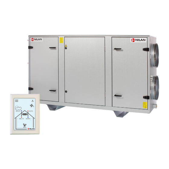
Control panel CTS602i HMI Touch With the CTS602i HMI Touch panel, Nilan's units can be controlled on-site. The control panel is connected to the CTS602i control unit in the factory via a connection box on the side of the plant, and comes with a 3 meter Cat.5e cable of the type 4x2x0.5mm pair cord. -
Page 25: Wall Bracket
VPM 120-560 (English) BY NILAN Wall bracket Mount the HMI panel on the wall using the integrated wall bracket. The panel should be visible so it is possible to change settings and to monitor warnings or alarms regarding operation. The wall bracket is located at the back of... -
Page 26: Electrical Connection Of Accessories
Electrical connection of accessories Connection to user selection and modbus User selection: Connection to the user selection can be used, for instance, to control operation of a cooker hood. This happens via a potential free contact in the cooker hood that sends a signal to the unit. -
Page 27: Water After-Heating Element (Accessory)
VPM 120-560 (English) BY NILAN Water after-heating element (accessory) CAUTION The circulation pump must be connected by an authorized electrician 1. The most optimal packing boxes to use by. pulling the cable to the circulation pump is found on the right side of the unit in a right-facing version and on the left side on a left-facing version. -
Page 28: Electrical After-Heating Element (Accessory)
Electrical after-heating element (accessory) CAUTION The connection of the electric heating element must be carried out by an authorized electrician. CAUTION The power supply cable must be connected via the main switch (accessory). ATTENTION Assembly of communication cable for board is performed in relation to the attached electrical diagram. -
Page 29: Plumbing Installation
INFO Nilan can supply a water trap with a ball. The ball ensures that no air blows into the unit through the condensate drain if the water trap dries out. This ensures that water in the condensate tray can drain off, which makes it unnecessary to check the condensate drain quite so often. -
Page 30: Plumbing Connections - Accessories
Plumbing connections - accessories Water trap with ball (option) Connection options with Nilan’s water trap: 1. Water trap with Ø32 mm reducing fitting 2. Reducing fitting for Ø20 mm 3. Reducing fitting for ¾" RG 4. Reducing fitting for ½" tube ATTENTION Water trap with ball can only be used at the condensation drain in the suction side of the unit. -
Page 31: Water After-Heating Element (Accessory)
VPM 120-560 (English) BY NILAN Water after-heating element (accessory) CAUTION The connection of the mixing loop to the heating surface must be carried out by an authorized plumber. ATTENTION If you install the unit outdoors or outside the climate screen of the building, the unit must be protected against frost. - Page 32 Nilan delivery: 1. Water after-heating element Supply flow 2. Actuator and control valve (loosely attached, the wiring is connected from the factory) B3 Frost thermostat sensor T9 temperature sensor Non-Nilan delivery: 3. Circulation pump (eg Grundfoss UPS 25-40 or equivalent) Return flow 4.
- Page 33 VPM 120-560 (English) BY NILAN Indicative performance data for built-in water-heating elements in VPM 120 The data given in table are based on a temperature before the heating surface of 10 ° C and 30% relative humidity. Supply air Pressure loss...
- Page 34 Indicative performance data for built-in water-heating elements in VPM 360 The data given in table are based on a temperature before the heating surface of 10 ° C and 30% relative humidity. Supply air Pressure loss Supply- / return- Output Pressure loss (air) Quantity of water Air volume [m...
-
Page 35: Ventilation Installation
ATTENTION To ensure the ventilation system operates optimally, it is important that it is balanced correctly. Nilan A/S recommends that it is done by professionals. ATTENTION If pressure control is purchased, the channel pressure must be set in the pressure control boxes... -
Page 36: Curves For Airflow Measurement
Curves for airflow measurement VPM 120 Assessment of electricity consumption at different air volumes / pressure losses. VPM120, Air performance curves Capacity Curve Pressure drop water coil [Pa] SFP [J/m3] 2100 1800 1500 1000 1200 1400 1600 1800 2000 VPM 240 Assessment of electricity consumption at different air volumes / pressure losses. -
Page 37: Vpm 360
VPM 120-560 (English) BY NILAN VPM 360 Assessment of electricity consumption at different air volumes / pressure losses. VPM360, Air performance curves Capacity Curve Pressure drop water coil [Pa] SFP [J/m3] 2500 2100 1800 1500 1000 1500 2000 2500 3000... -
Page 38: Vpm 560
VPM 560 Assessment of electricity consumption at different air volumes / pressure losses. VPM560, Air performance curves 1000 Capacity Curve Pressure drop water coil [Pa] SFP [J/m3] 2500 2100 1800 1500 1000 1500 2000 2500 3000 3500 4000 4500 5000 5500 6000 6500... -
Page 39: Maintenance And Cleaning
In order to ensure optimal operation of the unit, long service life and to ensure maximum hygiene standards, it is important to maintain and clean the unit as recommended by Nilan A/S. The following table provides indicative intervals for maintenance of the unit under normal operating conditions. -
Page 40: Replacement Of Filters
ATTENTION Nilan A / S recommends that the exclusions of filters of the types ISO ePM10> 50% filter (M5) or ISO ePM1> 70% filter (F7) be used. Incorrect filters can cause leakage problems in the unit as well as impaired filtration. -
Page 41: Ordering Spare Parts
VPM 120-560 (English) BY NILAN Ordering spare parts Filtre VPM 120 Type Number Nilan article number ISO ePM10 >50% filter (M5) 3948 ISO ePM1 >70% filter (F7) 3949 Filtre VPM 240 Type Number Nilan article number ISO ePM10 >50% filter (M5) 3950 ISO ePM1 >70% filter (F7) - Page 43 VPM 120-560 (English) BY NILAN...
- Page 44 United Kingdom: S L Services 25 St Leonards Road, Horsham RH13 6EH West Sussex Tlf. +44 (0) 7919 444452 stuart315@aol.com www.nilanuk.com Ireland: Nilan Ireland Ballylahive, Abbeydorney Tlf. +353 (0) 87 9798361 maurice@nilan.ie www.nilanireland.ie Nilan A/S Nilanvej 2 DK-8722 Hedensted Tlf.
Need help?
Do you have a question about the CTS602I HMI and is the answer not in the manual?
Questions and answers