Table of Contents
Advertisement
Quick Links
This Manual is prepared for the use of trained Vulcan Service
Technicians and should not be used by those not properly
qualified.
This manual is not intended to be all encompassing. If you have
not attended a Vulcan Service School for this product, you should
read, in its entirety, the repair procedure you wish to perform to
determine if you have the necessary tools, instruments and skills
required to perform the procedure. Procedures for which you do
not have the necessary tools, instruments and skills should be
performed by a trained Vulcan Service Technician.
The reproduction, transfer, sale or other use of this Manual,
without the express written consent of Vulcan, is prohibited.
This manual has been provided to you by ITW Food Equipment
Group LLC ("ITW FEG") without charge and remains the property
of ITW FEG, and by accepting this manual you agree that you will
return it to ITW FEG promptly upon its request for such return at
any time in the future.
A product of Vulcan-Hart
SERVICE MANUAL
VHU INSULATED HUMIDIFIED
CABINETS
VHU7
VHU18
- NOTICE -
3600 North Point Blvd Baltimore, MD 21222
F45642 (0217)
Advertisement
Table of Contents

Related Manuals for Vulcan-Hart VHU Series


Summary of Contents for Vulcan-Hart VHU Series
- Page 1 ITW FEG, and by accepting this manual you agree that you will return it to ITW FEG promptly upon its request for such return at any time in the future. A product of Vulcan-Hart 3600 North Point Blvd Baltimore, MD 21222 F45642 (0217)
-
Page 2: Table Of Contents
VHU INSULATED HUMIDIFIED CABINETS TABLE OF CONTENTS GENERAL ....................3 INTRODUCTION . -
Page 3: General
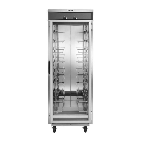
VHU INSULATED HUMIDIFIED CABINETS - GENERAL GENERAL Heating Elements INTRODUCTION Model Wattage Voltage Resistance This manual is applicable only to models listed on the VHU7 2000 cover page. Procedures in this manual will apply to all 6.57-7.66 (Optional) VHU18 models unless specified. Pictures and illustrations can be of any model unless they need to be model specific. -
Page 4: Service Procedures And Adjustments
VHU INSULATED HUMIDIFIED CABINETS - SERVICE PROCEDURES AND ADJUSTMENTS SERVICE PROCEDURES AND ADJUSTMENTS TEMPERATURE AND HUMIDITY CALIBRATION The oven and its parts are hot. Use care when operating, cleaning or servicing the oven. Check room temperature. Place temperature and humidity probe at the center of the cabinet. - Page 5 VHU INSULATED HUMIDIFIED CABINETS - SERVICE PROCEDURES AND ADJUSTMENTS Heating Elements Model Wattage Voltage Resistance VHU7 2000 6.57-7.66 (Optional) VHU18 Page 5 of 16 F45642 (0217)
-
Page 6: Removal And Replacement Of Parts
VHU INSULATED HUMIDIFIED CABINETS - REMOVAL AND REPLACEMENT OF PARTS REMOVAL AND REPLACEMENT OF PARTS TOP COVER COMPARTMENT FAN Disconnect the Disconnect the electrical power to the machine and electrical power to the machine and follow lockout / tagout procedures. follow lockout / tagout procedures. - Page 7 VHU INSULATED HUMIDIFIED CABINETS - REMOVAL AND REPLACEMENT OF PARTS Fig. 6 Remove two screws securing element. Fig. 7 Pull element out. Disconnect heating element wires. Fig. 8 Reverse procedure to install and check for proper Fig. 9 operation. Remove bottom screws from side panel. Air Element Remove pans and tray slides.
-
Page 8: Controller Board - Temperature & Humidity
VHU INSULATED HUMIDIFIED CABINETS - REMOVAL AND REPLACEMENT OF PARTS Fig. 13 Pull element out. Disconnect heating element wires. Fig. 10 Remove bottom cover screws. Fig. 14 10. Reverse procedure to install and check for proper operation. Fig. 11 Carefully clear element while lifting cover from CONTROLLER BOARD - right side. -
Page 9: Sensor Board - Temperature & Humidity
VHU INSULATED HUMIDIFIED CABINETS - REMOVAL AND REPLACEMENT OF PARTS Fig. 15 Lift controller board to access wire connections. Fig. 17 Note wire locations and disconnect from Remove double-sided tape from cabinet surface. controller board. Clean cabinet surface. Reverse procedure to install and check for proper operation. -
Page 10: Door Assembly
VHU INSULATED HUMIDIFIED CABINETS - REMOVAL AND REPLACEMENT OF PARTS Fig. 20 Release grommets from top panel. Fig. 22 Remain in control of door when removing hinges. Remove door hinge inside mounting screws from lower door hinge first. Fig. 21 Pull wire harness out. -
Page 11: Door Gasket
VHU INSULATED HUMIDIFIED CABINETS - REMOVAL AND REPLACEMENT OF PARTS Repeat each side to complete gasket installation. DOOR GASKET Check door for proper operation. Open door to access gasket. DOOR LATCH (MAGNETIC) Remove door gasket by pulling it out from retaining channel in door assembly. -
Page 12: Fuse Holder
VHU INSULATED HUMIDIFIED CABINETS - REMOVAL AND REPLACEMENT OF PARTS Fig. 29 Replace with same size and type of fuse. Reverse procedure to install and verify proper Install cover. operation. FUSE HOLDER Disconnect the electrical power to the machine and follow lockout / tagout procedures. -
Page 13: Electrical Operation
VHU INSULATED HUMIDIFIED CABINETS - ELECTRICAL OPERATION ELECTRICAL OPERATION COMPONENT LOCATIONS Fig. 30 Page 13 of 16 F45642 (0217) -
Page 14: Component Descriptions
VHU INSULATED HUMIDIFIED CABINETS - ELECTRICAL OPERATION Item Description Temperature & humidity Controller (behind control panel) Temperature Adjustment Humidity Adjustment Compartment Fan Heating element air (below bottom cover) Heating element humidity (below pan) Coated Pan Stainless Steel Pan Cooling Fan COMPONENT DESCRIPTIONS ITEM DESCRIPTION... -
Page 15: Wiring Diagram
VHU INSULATED HUMIDIFIED CABINETS - ELECTRICAL OPERATION WIRING DIAGRAM Fig. 31 NOTE: When temperature or humidity settings are SEQUENCE OF OPERATION changed, after a brief pause, both element relays (K1 & K3) will be de-energized and return to N.O. position. Conditions. -
Page 16: Troubleshooting
VHU INSULATED HUMIDIFIED CABINETS - TROUBLESHOOTING TROUBLESHOOTING TROUBLESHOOTING Symptom Possible Cause Cabinet not connected to power source or circuit breaker tripped. Cabinet not operating. Cabinet lighted power switch not ON or malfunctioning. Shorted heating element. Ground Fault Circuit Indicator (GFCI) Pinched/damaged wiring (heating elements or fan).
Need help?
Do you have a question about the VHU Series and is the answer not in the manual?
Questions and answers
I have a heated holding cabinet. It is giving me a code PRL that is not in my Manuel. What does this mean & what do I need to do? When it has that code on there it is not hot enough or it gets an electrical smell to it. When we open & close the door it than has the temp displayed instead of the code & starts to warm up & work properly.