Advertisement
Quick Guide
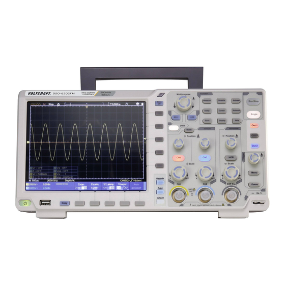
Front Panel
8
7
6
1. Display area
2. Control (button and knob) area
3. Probe Compensation: Measurement signal (5V/1kHz) output.
4. EXT Trigger Input
5. Signal Input Channel
6. Copy button: You can save the waveform by just pressing this button in any user
interface.
7. USB Host port: It is used to transfer data when external USB equipment connects to
the oscilloscope regarded as "host device". For example: Saving the waveform to USB
flash disk needs to use this port.
8. Power on/off
Backlight of this button:
Red light: The oscilloscope is turned off (connects with AC Power);
Green light: The oscilloscope is turned on.
Quick Guide
1
5
1
2
4
3
Advertisement
Table of Contents

Related Manuals for VOLTCRAFT DSO-6202F


Summary of Contents for VOLTCRAFT DSO-6202F
- Page 1 Quick Guide Quick Guide Front Panel 1. Display area 2. Control (button and knob) area 3. Probe Compensation: Measurement signal (5V/1kHz) output. 4. EXT Trigger Input 5. Signal Input Channel 6. Copy button: You can save the waveform by just pressing this button in any user interface.
-
Page 2: Rear Panel
Quick Guide Rear Panel 1. Handle 2. Air vents 3. Input terminals of optional multimeter 4. AC power input jack 5. Fuse 6. Foot stool: Adjust the tilt angle of the oscilloscope. 7. LAN port: the network port which can be used to connect with PC. 8. -
Page 3: Control Area
Quick Guide Control Area 1. Function button area: Total 11 buttons 2. Waveform generator controls (optional) DAQ: Multimeter (optional) recorder P/F: Pass/Fail W.REC: Waveform Record 3. Trigger control area with 2 buttons and 1 knob. The Trigger Level knob is to adjust trigger voltage. Other 2 buttons refer to trigger system setting. -
Page 4: User Interface Introduction
Quick Guide you can turn the M knob to select the menu or set the value. You can push it to close the menu on the left and right. User Interface Introduction 1. Waveform Display Area. 2. Run/Stop (touchable) The state of trigger, including: Auto: Automatic mode and acquire waveform without triggering. - Page 5 Quick Guide 11. It shows setting time. 12. It indicates that there is a USB disk connecting with the oscilloscope. 13. Multimeter window. 14. The pointer shows the trigger level position. 15. The waveform of CH1. 16. The two blue dotted lines indicate the horizontal position of cursor measurement. 17.
-
Page 6: Technical Specifications
Technical Specifications Technical Specifications Oscilloscope Vertical Resolution (A/D) Bandwidth Rise Time ≤ 1.75 ns 8 bits mode 200 MHz ≤ 2.33 ns 12 bits mode 150 MHz ≤ 17.5 ns 14 bits mode 20 MHz Performance Instruction Characteristics Horizontal Scale 1ns/div-1000s/div, step by 1 –... - Page 7 Technical Specifications Waveform Generator (Optional) Max Frequency 25 MHz (Sample 125 MS/s) or 50 MHz (Sample 250 MS/s) (optional) Output Channel Vertical Resolution 14 bits Amplitude Range 2 mVpp - 6 Vpp Waveform length Sine, Square, Ramp, and Pulse Standard Waveforms Multimeter (Optional) 3¾...
Need help?
Do you have a question about the DSO-6202F and is the answer not in the manual?
Questions and answers