
Related Manuals for ELKHART BRASS Cobra 7250 SD EXM


Summary of Contents for ELKHART BRASS Cobra 7250 SD EXM
- Page 1 7250 EXM Monitor Installation, Operating, & Maintenance Instructions 98493000 R 1-574-295-8330 www.elkhartbrass.com...
-
Page 2: Table Of Contents
TABLE OF CONTENTS PRODUCT SAFETY INFORMATION MONITOR CALLOUT DRAWING SYSTEM COMPONENTS INSTALLATION INSTRUCTIONS Installation Step 1: Mount and Wire all System Components Installation Step 2: Configure the EXM System Installation Step 3: Calibrate the EXM System Installation Step 4: Check Installation OPERATING INSTRUCTIONS MAINTENANCE INSTRUCTIONS SYSTEM SPECIFICATIONS... -
Page 3: Product Safety Information
PRODUCT SAFETY INFORMATION All personnel who may be expected to use this equipment must be thoroughly trained in its safe and proper use. Before flowing water from this device, check that all personnel (fire service and civilian) are out of the stream path. Also, check to make sure stream direction will not cause avoidable property damage. -
Page 4: Monitor Callout Drawing
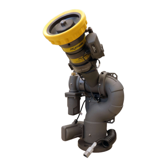
MONITOR CALLOUT DRAWING X-Stream Series Master Stream Nozzle Double Race Bearings 3.5” NHT Discharge Manual Override Absolute Position Feedback Sealed High- Fully Vaned Cast Torque Gearmotor Aluminum Waterway Double Race Bearings 3” 150# Flange (other base options available) 7250 Monitor... -
Page 5: System Components
SYSTEM COMPONENTS MONITOR Monitor – 7250 monitor is specially designed to be compact providing a greatly reduced swing radius. Unique waterway swivel joints utilize stainless steel thrust rods, and needle roller thrust bearings, for unprecedented durability in a range of applications. utilizes a cast vanned waterway to minimize large-scale turbulence. - Page 6 CONTROL Joystick Controller - 7030 The Joystick Controller must be used in conjunction with the 7070 OEM Interface Module (Joystick and OEM Interface Module can be ordered together as the 7035 package). The Joystick Controller can be mounted inside the apparatus cab to control all monitor functions, including oscillation.
- Page 7 OEM Interface Module - 7070 The OEM Interface Module is used in conjunction with either the Elkhart Brass or customer supplied joystick, or OEM installed switches. The OEM Interface Module may be configured to handle switching power or ground. The Interface Module provides the option of mounting a joystick or switches in the apparatus cab to control all monitor functions, including oscillation.
- Page 8 Light Kit – 7083/7084 The Light Kit provides illumination specifically for the areas targeted by EXM monitors. The Light Kit is mounted on top of the discharge elbow and follows the aim of the monitor. Installation instructions are included with the light kit. 7083 –...
-
Page 9: Installation Instructions
INSTALLATION INSTRUCTIONS Installation Overview: Step 1 – Mount and Wire All System Components Step 2 – Configure the EXM System (If Required) Recommended electrical requirements for monitor: Power and Ground wire gauge and length: Distance Ft.(m) Wire Gauge (AWG) 100(30.5) –... -
Page 10: Installation Step 1: Mount And Wire All System Components
When using CAN lines for communication there must be 2 termination points within the system. Termination points are explained further in the Configuration section (installation step 2). What is important at this time is that in order to maximize the efficiency of communication in your CAN network, you must terminate the two components at the extreme ends of your main CAN line. - Page 11 Caution: Do NOT use motors or discharge as leverage to tighten monitor. Warning: When installing the monitor on a raised face companion flange, it is critical that the bolts be tightened uniformly to prevent misalignment of the monitor relative to the flange or valve. If the monitor becomes misaligned, the base flange will fracture and fail when the bolts on the “high”...
- Page 12 Connecting an OEM supplied proximity sensor to the wire from position 3 will provide conditional extended travel functionality via a ground or open circuit (see Operating Instructions). Connecting the proximity sensor wire from position 3 to a ground will provide an always enabled extended travel.
- Page 13 Handheld Controller and Docking Station – Using the Docking Station template shown in the Component Mounting Templates section, drill all 7/32” holes shown through the panel intended for mounting the Docking Station. Mount the Docking Station with the supplied 10-24 x 3/8”...
- Page 14 Joystick Controller and OEM Interface Module – Using the Joystick Controller template shown in the Valve Plug Component Mounting Templates section, drill all holes shown through the panel intended for mounting the Joystick Controller. Mount the Joystick Controller using 10-24 x ½” fasteners secured with blue Loctite 242 or equivalent.
- Page 15 If using a customer-supplied joystick or switches, all controls being used with the OEM Interface Module must be customer-supplied. o Customer-supplied controls/switches and the Elkhart Brass Joystick may not be used simultaneously. If there are any unused OEM Interface Module connections plug the connections with appropriate Deustch connectors and plugs.
- Page 16 Supply power to the Position Feedback Display by connecting plug 1 leads to an appropriate power source. Install a 1 Amp fuse into the positive power lead of the Position Feedback Display for a 12V system (1/2 Amp for 24V system). ...
- Page 17 o If the Stow Module will be a termination point (at the extreme end of your main CAN line), install the supplied jumper between positions 8 & 9 of the Stow Module Harness. Jumper Jumper Connect the Stow indicator leads of the Stow Module Harness to the customer supplied devices that the Stow Module is to actuate.
- Page 18 Install the valve into the water supply line. Supply power to the valve by connecting the red and black leads coming from the valve plug to an appropriate power source. Using the black, green, and blue leads from the plug, connect the valve to the appropriate CAN line.
-
Page 19: Installation Step 2: Configure The Exm System
Installation Step 2: Configure the EXM System NOTE: EXM systems using CAN communication and consisting of a monitor and one controller (panel mount or OEM interface) do not require configuration. EXM monitors and controllers come factory set for CAN termination. A position feedback display can also be used without the need for configuration;... -
Page 20: Installation Step 3: Calibrate The Exm System
Installation Step 3: Calibrate the EXM System After successfully configuring the system, the system must be calibrated. Calibrating the EXM system’s horizontal and vertical rotation is a necessary step for EXM systems of all types. To view a demonstration of system calibration and entering setup commands go to www.elkhartbrass.com to download the appropriate EXM System Instructional Video. - Page 21 If an Elkhart Brass Unibody valve is being used in your system, calibrate it at this time by first placing the valve in a half open position, and then pressing and holding the CLOSE and PRESET buttons on any controller until the valve calibration begins.
-
Page 22: Installation Step 4: Check Installation
Installation Step 4: Check Installation After mounting, wiring, configuring, and calibrating the EXM system, check the installation of the entire EXM system. Ensure that all components have been mounted securely and have had the correct fuses installed within their wiring leads. ... -
Page 23: Operating Instructions
OPERATING INSTRUCTIONS To view a demonstration of some operating commands go to www.elkhartbrass.com download the appropriate EXM System Instructional Videos. A. Button / Joystick Operation STREAM – Moves the nozzle in order to OSC (OSCILLATE) – Used to set flow a straight stream of water automatic motion of the monitor (Roll thumbwheel forward on the... - Page 24 or itself as this will cause the motors to over current. The monitor may need to be manually reversed if this occurs. C. Re-calibrating Horizontal and Vertical Rotation Calibrating the EXM system’s horizontal and vertical rotation is a necessary step for EXM systems of all types.
- Page 25 o The vertical travel limit should be set within the total allowed factory set travel or total travel specified during configuration of the system. If a travel limit is set outside the intended operating area, operation of the monitor may be unpredictable. o To set the highest travel point, hold the STREAM button, press the UP button, then release both buttons.
- Page 26 Important: If using a Position Feedback Display with an extended travel monitor, the position display will need to be calibrated after setting new limits. F. Keep-Out Zones Keep-Out Zones are used when it is desired to restrict the motion of the monitor to a smaller more specific range than that set during system calibration.
- Page 27 Figure 1: Keep-Out Zones G. Stow Position The Stow Position is a preset position that can be used to bring the monitor into a position suitable for when the system is powered off. A stow position must be within the allowed travel area defined by any travel limits or keep-out zones, therefore it is recommended that travel limits and keep-out zones are set before setting a stow position.
- Page 28 The Clear All Function allows the user to remove any Travel Limits, Keep-Out Zones, or Stow Positions set while in Setup Mode. When the Clear All Function is used, it will remove all of the previously listed operations. The Clear All Function will not affect calibration points, Motor Speed, or Preset valve positions.
- Page 29 OPEN – opens the valve. If the button is released, the valve will remain in the current position until another valve operation is performed. o In order to initiate auto-travel open, press and hold the OPEN button, then press and release the CLOSE button, then release the OPEN button.
- Page 30 USB mode). Contact Elkhart Brass to make arrangements to send the EBDIAG.CSV file for review. O. Update Firmware ...
-
Page 31: Maintenance Instructions
If the update did not perform correctly, the preset LED will blink three times every three (3) seconds. If the update did not perform correctly please call Elkhart Brass at (800) 346-0250. Remove the USB flash drive from the input controller to exit USB Mode. (On older systems it may be necessary to push the right button on the panel mount or hand held, or move the joystick right, to exit USB mode). - Page 32 During nozzle flow test, inspect monitor swivel joints and water valve for leaks Inspect all exposed wiring for signs of damage If a Docking Station is used in the EXM system, use a clean cloth to wipe clean the brass contacts on both the Docking Station and any Handheld controllers used with the station.
- Page 33 If the Docking Station LED is rapidly flashing red (6 flashes per second), this could mean that the Handheld battery pack of the controller being charged is bad. If this occurs, contact an Elkhart Brass representative for further instruction.
-
Page 34: System Specifications
SYSTEM SPECIFICATIONS 7250 EXM Monitor Max Flow Rating 1500 GPM (5678 LPM) Max Operating Pressure 250 PSI Continuous (17.2 BAR) 500 PSI Limited Duty (34.5 BAR) [50% / 1hr (30min on / 30 min off)] Inlet Size 3”-150# Flange, DN80-PN16 Flange, 4”-150# Flange, 3”... - Page 35 Fuse Rating 1 AMPS (12V) & 0.5 AMPS (24V) RF power output Meets FCC part 15 requirements for license free operation (Output if applicable) Transmitter dimensions 7 17/32” x 3 19/32” X 1 1/8” Transmitter weight 0.815 lbs.
- Page 36 Fuse Rating 1 AMPS (12V) & 0.5 AMPS (24V) Dimensions 5.24” x 4.68” x 1.42” Transmitter weight 1.15 lbs. Operating temperature range -40 F to +158 F (-40 C to +70 Environmental Rating NEMA 4 J1939 CAN Communication Structure Preliminary Configuration for Input Control CAN Settings: J1939_SOURCE_ADDRESS address range for monitors = 0x80-9F, 0xF0-0xF1...
- Page 37 5.1-5.7 6 bits Reserved 1 byte Group Number of Input Controller sending message (1-15) 1 byte Reserved Monitor Position Feedback Message Repetition rate: 100mS Data Length: Extended Data Page: Data Page: PDU Format: PDU Specific: Default Priority: Parameter Group Number: 255,240 (0x00FFF0) – broadcast message Start Position Length Parameter 1 byte...
-
Page 39: Component Mounting Templates
COMPONENT MOUNTING TEMPLATES NOTE: Pages must NOT be scaled during printing or template size will be scaled incorrectly. Panel Mount Controller Mounting Template... - Page 40 Docking Station Mounting Template Position Display Indicator Mounting Template...
- Page 41 Joystick Controller Mounting...
- Page 42 EXM CAN Stow Module OEM Interface Module Mounting Template Mounting Template...
- Page 44 LKHART RASS : 1302 W • E , IN 46514 HYSICAL EARDSLEY LKHART : P.O. B 1127 • E , IN 46515 AILING LKHART : 1-574-295-8330 • 1-800-346-0250 HONE : 1-574-293-9914 WWW.ELKHARTBRASS.COM © E ., I . 2014 LKHART RASS 7250 EXM M ONITOR NSTALLATION...
Need help?
Do you have a question about the Cobra 7250 SD EXM and is the answer not in the manual?
Questions and answers