Table of Contents
Advertisement
Quick Links
Instruction Booklet IB 52-01-TE
Instructions for the Eaton Type CM52
Network Protectors 800 to 4500 Amperes
Effective October 2010
Supersedes November 2008
Read and understand these instructions before
attempting any assembly, operation, or
maintenance of the Network Protector.
See important disclaimer of warranties and
limitation of liability on page ii
See important safety information on page iii and iv.
Advertisement
Table of Contents

Related Manuals for Eaton CM52


Summary of Contents for Eaton CM52
- Page 1 Effective October 2010 Instruction Booklet IB 52-01-TE Supersedes November 2008 Instructions for the Eaton Type CM52 Network Protectors 800 to 4500 Amperes Read and understand these instructions before attempting any assembly, operation, or maintenance of the Network Protector. See important disclaimer of warranties and limitation of liability on page ii See important safety information on page iii and iv.
- Page 2 The information, recommendations, descriptions and safety notifications in this document are based on Cutler-Hammer’s experience and judgment with respect to CM52 NETWORK PROTECTORS. THIS INFOR MATION SHOULD NOT BE CONSIDERED TO BE ALL INCLUSIVE OR COVERING ALL CONTINGENCIES. If further information is required, Cutler-Hammer should be consulted.
- Page 3 Extensi ve us e has been made of barriers and The safety notati ons are headed by one of three haz ard interloc ks in the CM52 N etwor k Protectors to intensity levels whic h are defined as follows : provide greater safety to maintenance pers onnel.
- Page 4 Instruction Booklet IB 52-01-TE Instructions for the Eaton Type CM52 Network Protectors 800 to 4500 Amperes Effective October 2010 IB -52-01-TE CAUTION The network protectors described in this book were designed and tested to operate within their nameplate ratings. Operation outside of these...
-
Page 5: Table Of Contents
4.5 Arc Chambers..................................9 4.5.1 Arc Chutes................................9 4.6 Electronic Tripping System .............................9 4.7 Internal Electrical Accessories............................10 Electrical Testing..................................11 Manual Closing of the CM52 B reaker..........................12 Section V – Renewal Parts 5.1 Renewal Parts list................................12 Diagrams....................................13-18 Addendum-Electrical Saf ety Interlock..........................19 Addendum-Handle Change Instructions..........................20 Addendum-Hardware Bag Kits.............................22... - Page 6 Effective October 2010 IB -52-01-TE LIS T OF TABLES Table Description Page CM52 Ratings Table – Ratings tested at 600V Weights of Draw out Units LIS T OF ILLUS TRATIONS (Not including addendums) Figure Title Page CM52 800A - 2000A Network Protector...
- Page 7 Instructions for the Eaton Type CM52 Instruction Booklet IB 52-01-TE Network Protectors 800 to 4500 Amperes IB -52-01-TE Effective October 2010 Table 1- CM52 Ratings Table – Ratings tested at 600V Continuous Breaker CM52 CM52 IEEE/ANSI IEEE/ANSI Current Element Interrupting...
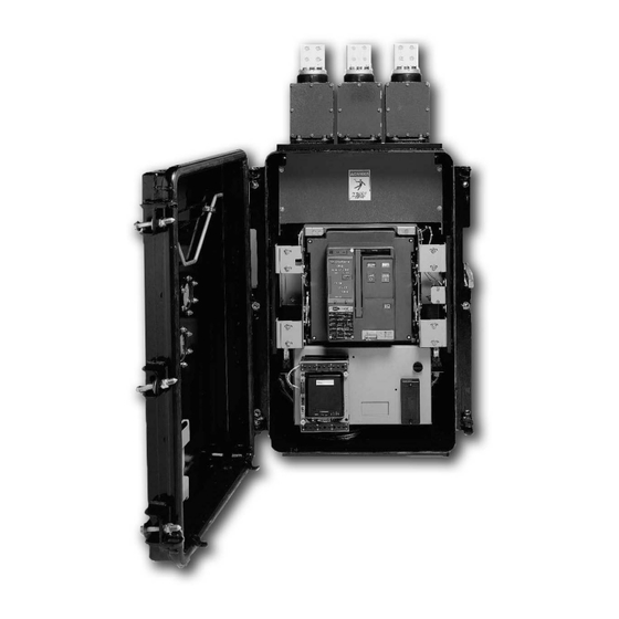
- Page 8 Network Protectors 800 to 4500 Amperes Effective October 2010 viii IB -52-01-TE Fig. 1 CM52 800A - 2000A Network Protector Fig. 1A 3500A - 4500A Network Protector (NOTE: 2250A – 3000A Not Shown) viii Effective 11/05/08 (super cedes 11/19/03) IB 52-01-TE viii EATON COrPOrATION www.eaton.com...
-
Page 9: Introduction
CAUTION provide protection for personnel against contact with energized components while disconnecting IT IS NOT SAFE TO OPERATE THE CM52 the unit for test or maintenance. All the main NETWORK PROTECTORS UNLESS THEY current carrying and mechanical operating ARE INSTALLED IN A SUITABLE METAL components are located behind a “... - Page 10 Technical Data Spot Network Systems Cutler-Hammer Instruction Booklet IB 52-01-TE Instructions for the Eaton Type CM52 Page 24 Effective: August 1999 Network Protectors 800 to 4500 Amperes Effective October 2010 This page intentionally left blank. TD.52.01A.T.E EATON COrPOrATION www.eaton.com...
-
Page 11: Section I - Receiving, Handling And Storing
Type NPL fuses, and are supplied with spade terminals or threaded studs. The type MPC series solid-state n etwork protector rel ay is supplied with the CM52 network protector mounted on the relay pan el. For use of the MPC series relay, please refer to relay I.B. -
Page 12: Section Ii - G Eneral Description
2.0 GENERAL The standard submersible enclosure is equipped with type NPL fuses in externally mounted fuse Type CM52 network protector is a special air housing located on top of the network body. The circuit breaker equipped with a relay that CM52 is also available with internal fuses. -
Page 13: Cm52 Network Protector
Relay Module Layout 2.1.1 Cassette Frame The relay module of the CM52 has a swing open The supporting structure of the break er and relay front panel that permits the replacement of the module is mounted directly in the enclosure. -
Page 14: Section Iii - Operation
Instruction Booklet IB 52-01-TE Instructions for the Eaton Type CM52 Network Protectors 800 to 4500 Amperes Effective October 2010 IB -52-01-TE the block , while all customer connections can be 3.1.1 To Open Door made on the front portion of the blocks. There is... -
Page 15: Enclosure
CONNECT position. ENERGIZED TRANSFORMER TO AN ENERGIZED NETWORK SYSTEM. ENCLOSURE The CM52 submersible enclosure is o f welded The operating handle has three positions: OPEN, steel constru ction, which has b een bonderi zed AUTO and CLOSE as indicated on the and protect ed by several coats of high-grade nameplate located directly beside the handle. -
Page 16: Mechanical Anti-Close Interlock
It will also prevent electrical closure of the majority of features are common to both break er in the instance where a CM52 breaker is con figurations and will be discussed in this being connected (levered-in) to en ergize bus and section. -
Page 17: Pole Unit
Instructions for the Eaton Type CM52 Instruction Booklet IB 52-01-TE Network Protectors 800 to 4500 Amperes Effective October 2010 IB -52-01-TE construction provides high strength structural connect ed to the load conductor through flexible properties, excellent dielectric ch aracteristics and braided connectors. -
Page 18: Primary Stationary Contacts
Instruction Booklet IB 52-01-TE Instructions for the Eaton Type CM52 Network Protectors 800 to 4500 Amperes Effective October 2010 IB -52-01-TE the front mounted charging handle and M anual 4.3.2 Primary Stationary Contacts “ ON” buttons and Manual “OFF” buttons. -
Page 19: Anti-Pump Feature
Effective October 2010 4.4.2 Anti-Close Feature The CM52 circuit breaker cont ains an auxiliary relay that is energized when the MPC series relay calls for a trip. This relay has a contact in series with the motor circuit, isolating the motor closing scheme. -
Page 20: Internal Electrical Accessories
Spring Release – The spring release is a POWER ON (Yellow LED) • standard devi ce on the CM52 Network Protector Indicates the presence of normal power Circuit Breaker. It remotely closes the circuit input to the IDM. -
Page 21: Electrical Testing
Network Protectors 800 to 4500 Amperes IB -52-01-TE Effective October 2010 Electrical Testing Three phase testing of the type CM52 can be accomplished in the following manner: Vent the hinge side (if submersible) Open the enclosure door aft er the breaker has been TRIPPED. -
Page 22: Manual Closing Of The Cm52 B Reaker
12. Lifting Brackets 13. Lever-in Crank w/10mm Socket With the breaker racked out on its rails, the 14. Arc Chute Assembly CM52 breaker can be manu ally closed (fo r 15. Test Switch. maintenance purposes only). WARNING DO NOT ATTEMPT TO MANUALLY CLOSE A CM52 BREAKER ON TO AN ENERGIZED SYSTEM. -
Page 23: Diagrams
Instructions for the Eaton Type CM52 Instruction Booklet IB 52-01-TE Network Protectors 800 to 4500 Amperes IB -52-01-TE Effective October 2010 800A – 2000A 216Y/125 S CHEMATIC Effective 11/05/08 (super cedes 11/19/03) IB 52-01-TE EATON COrPOrATION www.eaton.com... - Page 24 Instruction Booklet IB 52-01-TE Instructions for the Eaton Type CM52 Network Protectors 800 to 4500 Amperes Effective October 2010 IB -52-01-TE 800A - 2000A 480/277 S CHEMATIC Effective 11/05/08 (super cedes 11/19/03) IB 52-01-TE EATON COrPOrATION www.eaton.com...
- Page 25 Instructions for the Eaton Type CM52 Instruction Booklet IB 52-01-TE Network Protectors 800 to 4500 Amperes Effective October 2010 IB -52-01-TE 2250A – 3000A 216Y/125 S CHEMATIC Effective 11/05/08 (super cedes 11/19/03) IB 52-01-TE EATON COrPOrATION www.eaton.com...
- Page 26 Instruction Booklet IB 52-01-TE Instructions for the Eaton Type CM52 Network Protectors 800 to 4500 Amperes Effective October 2010 IB -52-01-TE 2250A – 3000A 480Y/277 S CHEMATIC Effective 11/05/08 (super cedes 11/19/03) IB 52-01-TE EATON COrPOrATION www.eaton.com...
- Page 27 Instructions for the Eaton Type CM52 Instruction Booklet IB 52-01-TE Network Protectors 800 to 4500 Amperes Effective October 2010 IB -52-01-TE 3500A – 4500A 216Y/125 S CHEMATIC Effective 11/05/08 (super cedes 11/19/03) IB 52-01-TE EATON COrPOrATION www.eaton.com...
- Page 28 Instruction Booklet IB 52-01-TE Instructions for the Eaton Type CM52 Network Protectors 800 to 4500 Amperes Effective October 2010 IB -52-01-TE 3500A – 4500A 480Y/277 S CHEMATIC Effective 11/05/08 (super cedes 11/19/03) IB 52-01-TE EATON COrPOrATION www.eaton.com...
-
Page 29: Addendum-Electrical Saf Ety Interlock
N.O. contact in the close The CM52 Network Protector is supplied with as circuit (Fig. 2), this would prevent an automatic standard,... -
Page 30: Addendum-Handle Change Instructions
Instruction Booklet IB 52-01-TE Instructions for the Eaton Type CM52 Network Protectors 800 to 4500 Amperes Effective October 2010 IB -52-01-TE Addendum II to IB-52-01-TE Instructions for Changing Handle Position Right to Left Side of Tank It assumed that this conversion would be performed prior to the unit being placed into service in the field in a de-energized state. - Page 31 Instructions for the Eaton Type CM52 Instruction Booklet IB 52-01-TE Network Protectors 800 to 4500 Amperes Effective October 2010 IB -52-01-TE 6. Remove Bearing Seal Cover and O-Ring Seal. (Note that this includes 2 Backing Rings on each side of an O-Ring with the Concave side of the backing ring toward the O-ring.) 7.
-
Page 32: Addendum-Hardware Bag Kits
Instruction Booklet IB 52-01-TE Instructions for the Eaton Type CM52 Network Protectors 800 to 4500 Amperes Effective October 2010 IB -52-01-TE 9. Remove shaft assembly from the side of the cassette 10. Remove Right Hand mounting bracket from the blue “43” switch and install the Left Hand Bracket (provided in handle conversion kit onto the existing switch). - Page 33 Instructions for the Eaton Type CM52 Instruction Booklet IB 52-01-TE Network Protectors 800 to 4500 Amperes Effective October 2010 IB -52-01-TE 17. Remove (2) spring Nuts that hold the switch bracket in the “U” channel by Pushing down and turning to lift out of the Right Hand channel. Transfer the nuts into the Left Hand Channel.
-
Page 34: Addendum-Maintenance Procedure
Instruction Booklet IB 52-01-TE Instructions for the Eaton Type CM52 Network Protectors 800 to 4500 Amperes Effective October 2010 IB -52-01-TE 23. Hook spring on handle ear and Network Protector bracket. 24. Rotate the handle to AUTO position while applying inward pressure. - Page 35 Instructions for the Eaton Type CM52 Instruction Booklet IB 52-01-TE Network Protectors 800 to 4500 Amperes Effective October 2010 IB -52-01-TE 26. Loosen Front Bracket plates to set the claw position. This claw engages the wire form that runs through the breaker element.
- Page 36 IB -52-01-TE Addendum III to IB-52-01-TE CM52 Hardware Bags Every Eaton Corporation CM52 Network Protector is supplied with the necessary hardware to mate to its corresponding Network Transformer. Listed below are each bag, its hardware contents and picture representation. Handle Change Bag (Used to change handle from Left to Right)
- Page 37 Instructions for the Eaton Type CM52 Instruction Booklet IB 52-01-TE Network Protectors 800 to 4500 Amperes Effective October 2010 IB -52-01-TE 2250-3000A CM52 Hardware Bag (# 680C602G08) Qty (12) .50 X 2.25” Bolt, Qty (12) .50 X 3.25” Bolt, 70100EG07Q (Flex connection)
- Page 38 Instruction Booklet IB 52-01-TE Instructions for the Eaton Type CM52 Network Protectors 800 to 4500 Amperes IB -52-01-TE Effective October 2010 Addendum IV to IB-52-01-TE Maintaining the CM-52 Network Protector 1. Clean top of Network Protector to prevent contamination by dirt and debris 2.
- Page 39 Instructions for the Eaton Type CM52 Instruction Booklet IB 52-01-TE Network Protectors 800 to 4500 Amperes Effective October 2010 IB -52-01-TE Lift the levering crank access door and insert the end of the • levering crank (3/8 ” square). As the levering crank is turned...
- Page 40 Instruction Booklet IB 52-01-TE Instructions for the Eaton Type CM52 Network Protectors 800 to 4500 Amperes Effective October 2010 IB -52-01-TE Push the button labeled “PUSH OFF”. The breaker will OPEN.The main and arc contacts should • only be dressed with fine scotch bright if there is black carbon residue from arcing. Do not use a file on the contacts.
- Page 41 Instructions for the Eaton Type CM52 Instruction Booklet IB 52-01-TE IB -52-01-TE Network Protectors 800 to 4500 Amperes Effective October 2010 Check the input sequence light on the test set before you switch the • test set on, this indicates that you hav e the correct phasing. If the light is ON, Do Not turn th e test set on.
- Page 42 The sole source governing the rights and remedies of any purchaser of this equipment is the contract between the purchaser and Eaton. NO WARRANTIES, EXPRESSED OR IMPLIED, INCLUDING...
Need help?
Do you have a question about the CM52 and is the answer not in the manual?
Questions and answers