Lunos Smart Comfort 5/SC-FT Installation And Operating Manual
Hide thumbs
Also See for Smart Comfort 5/SC-FT:
- Installation and operating manual (20 pages) ,
- Functional description (27 pages)

Related Manuals for Lunos Smart Comfort 5/SC-FT


Summary of Contents for Lunos Smart Comfort 5/SC-FT
-
Page 1: Table Of Contents
Installation and Operating Manual Smart Comfort 5/SC-FT - Please forward to the user - Contents: Page: About this manual, Safety instructions, Disposal Technical data, Shipping unit Installation Electrical connection Programming of the device type Operating element - setting options Factory settings, Frost protection... -
Page 2: About This Manual, Safety Instructions, Disposal
About this manual Read this manual carefully and completely before assembly! Always ob- serve the general safety instructions and the safety symbols with informa- tion in the text. Hand out this manual to the user (tenants, proprietors, property manage- ment etc.) after completing assembly. -
Page 3: Technical Data, Shipping Unit
Technical data Control Power supply units Operating voltage: 12 V DC Input voltage: 100 - 240 V AC Functional voltage range: 0 - 10 V Output voltage: 12 V DC Types: Operational switching current: max. 5 A Connected load: max. 60 W 5/NT18 18 Watt Order No.: 039 973... - Page 4 Operating element with frame □ □ Power supply Example 5/NT18 Ø 55 Dimensions in mm...
-
Page 5: Installation
Installation The control unit, the operating element and the power supply can be appropriately installed in a standard switch box (90 mm deep), as shown. 90 mm Ø 60 If the power supply is installed at a Power supply (to be different location, a connected according to simple, 42 mm... - Page 6 Control unit Colour-marked wire Operating element (View from behind without frame) Plug the operating element and the control unit together correctly, using the colour-marked wire of the connection cable for orientation.
-
Page 7: Electrical Connection
Electrical connection Safety instructions Caution! Any assembly work may only be carried out after disconnecting the supply voltage! Before connecting the device to the mains voltage, make sure that all connection lines are voltage-free (dead)! (Separation from the power supply with a minimum contact opening of 3 mm, e.g. electric fuse). Each electric circuit of this ventilation system must be fitted with a resi- dual current protection (e.g. - Page 8 Electrical connection series e² Maximum number of connectable ventilation units: Connection of the control Power supply e² unit on the unit back of the 5/NT18 operating 5/NT60 element 5/NT100 10 + 10 Device 1;3;5 Device 2;4;6 From/To To/From rd bl pu rd bl pu Colour-marked wire Note: Connect the...
- Page 9 Electrical connection e Maximum number of connectable ventilation Connection units: of the control Power supply unit on the unit back of the 5/NT18 operating 5/NT60 element 5/NT100 5 + 5 + - S1 + - S2 Connection Colour-marked board e wire + 12 V blue...
- Page 10 Electrical connection RA 15-60 Maximum number of connectable ventilation units: Connection of the control Power supply RA15-60 unit unit on the back of the 5/NT18 operating 5/NT60 element 5/NT100 1 + 2 * Connection available for another RA 15-60. Ensure star- shaped arrangement when connecting two RA 15-60s.
- Page 11 Connection of Electrical connec- the control tion with further control 5/UNI-FT unit on the back of the operating element Colour-marked wire + 12 V Connecting Control unit ventilation units to the 5/UNI-FT! You have the option of up to 10 5/UNI-FT in a star shape to connect to a control unit! 5/UNI-FT...
-
Page 12: Programming Of The Device Type
Programming of the device type If the "Event" button is pressed for 10 seconds or longer, you enter the device mode. This is confirmed by a permanent flashing of the Event LED. The connected fan type can now be selected via the "Fan" button. The fan type is accepted after 10 seconds without input. -
Page 13: Operating Element - Setting Options
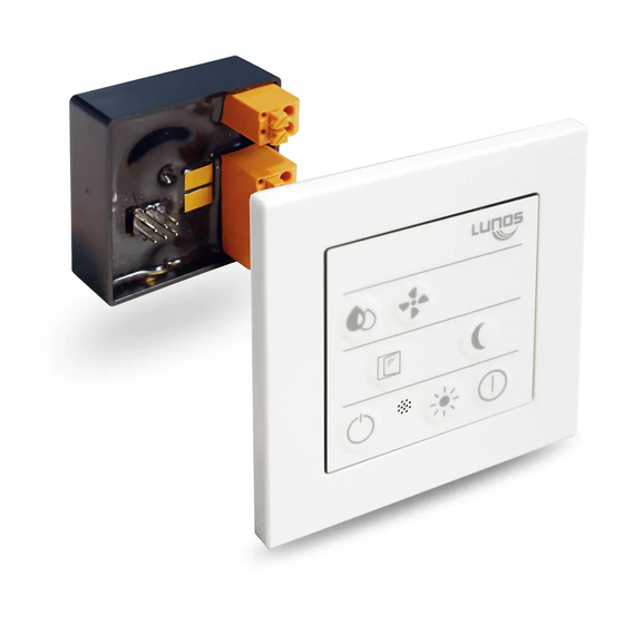
Switching on the ventilation system Switching off the ventilation Setting of the LED system brightness level Resetting the filter replace- Programming of the device ment type An advanced feature description can be found on www.lunos.de! - Page 14 The Smart Comfort offers you the possibility to switch all functions of your ventilation devices and to recognize their current operating status. It contains a humidity sensor, which controls the ventilation de- vices appropriately in automatic operation. Drop The humidity-sensitive automatic mode is activated or deacti- vated via the button with the drop symbol.
- Page 15 Window The window symbol stands for the intensive ventilation mode. When actived, the LED next to the symbol illuminates conti- nuously and the fans change to the highest available ventilati- on stage. The mode automatically ends after the set time (factory setting: 30 minutes).
- Page 16 You can use the buttons described above to carry out further programming. It is also possible to set the operating times and ventilation stages of the com- fort functions as well as to calibrate the airflow volumes of your ventilation units. For further information, please contact LUNOS Lüftungstechnik GmbH für Raumluftsysteme.
-
Page 17: Factory Settings, Frost Protection
Factory settings The factory settings are as follows: Device type: e² Automatic mode: the lowest stage in humidity-sensitive mode is the lowest ventilation stage, i.e. without OFF. Control range 50% -70% Intensive ventilation: active for 30 minutes, highest ventilation stage ... -
Page 18: Filter Replacement And Filter Cleaning
Filter replacement and filter cleaning The Event LED of the operating Example inner screen e² element illuminates continuous- ly to signalise that a filter is Filter dirty. Remove the inner screen of the ventilation unit, remove the filter, insert the new or cleaned filter, put the inner screen back Reset the filter monitoring display by pressing the “Event“... - Page 19 Notes...
- Page 20 Notes LUNOS Germany LUNOS Lüftungstechnik GmbH Phone +49 30 362 001-0 für Raumluftsysteme +49 30 362 001-89 Wilhelmstr. 31 info@lunos.de 13593 Berlin ∙ Germany www.lunos.de...
Need help?
Do you have a question about the Smart Comfort 5/SC-FT and is the answer not in the manual?
Questions and answers