
Related Manuals for Lenze Digitec EPM-H605


Summary of Contents for Lenze Digitec EPM-H605
- Page 1 EDBPM−H605 .7[\ Betriebsanleitung Operating Instructions Instructions de mise en service EPM−H605, EPM−H606 Bedieneinheit Operating unit Unité de commande µ...
- Page 2 Lesen Sie zuerst diese Anleitung, bevor Sie mit den Arbeiten beginnen! Beachten Sie die enthaltenen Sicherheitshinweise. Please read these instructions before you start working! Follow the enclosed safety instructions. Veuillez lire attentivement cette documentation avant toute action ! Les consignes de sécurité doivent impérativement être respectées.
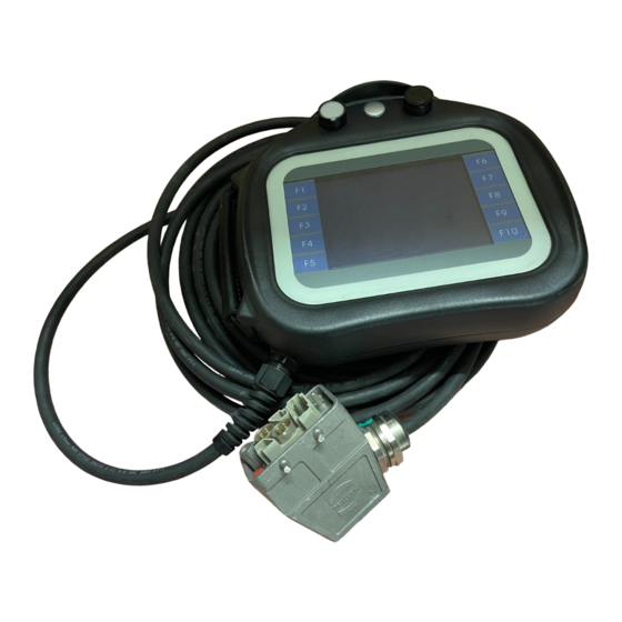
- Page 3 h605_002...
- Page 4 Legende zur Übersicht Beschreibung Leuchttaster, weiß (1 Schließer) EPM−H605: Stopp−Taster mit Stoppfunktionalität (2 Öffner) EPM−H606: Ohne Taster Taster, schwarz (1 Schließer) Funktionstasten 1 ... 10 (Funktionen über Software programmierbar) Regulierbare Handschlaufe Haken für Wandbefestigung Dreistufiger Zustimmtaster µ EDBPM−H605 DE/EN/FR 6.0...
- Page 5 ... die Bedieneinheiten EPM−H605 und EPM−H606 ab der Typenschildbezeichnung: Typenschild H60x Produktreihe Bedieneinheit H605 ohne Stecker H606 mit Stecker Made in Italy Lenze Hans-Lenze-Straße 1 Type D-31855 Aerzen ID-No Order Hardwarestand Data: 1A, 1B mit 42−poligem Stecker mit 20−poligem Stecker Softwarestand µ EDBPM−H605 DE/EN/FR 6.0...
- Page 6 © 2007 Lenze Digitec Controls GmbH, Grünstr. 36, D−40667 Meerbusch Ohne besondere schriftliche Genehmigung von Lenze Digitec Controls GmbH darf kein Teil dieser Dokumentation vervielfältigt oder Dritten zugänglich gemacht werden. Wir haben alle Angaben in dieser Dokumentation mit größter Sorgfalt zusammengestellt und auf Übereinstim- mung mit der beschriebenen Hard−...
-
Page 7: Table Of Contents
Inhalt Vorwort und Allgemeines ......... . . Über diese Betriebsanleitung . - Page 8 Inhalt Inbetriebnahme ........... Wichtige Hinweise .
-
Page 9: Vorwort Und Allgemeines
Vorwort und Allgemeines Mit den Bedieneinheiten EPM−H605 und EPM−H606 können Sie auf Codestellen von Lenze Antriebsreglern, Servo PLC 9300 und Drive PLC zugreifen und diese auf komfortable Weise steuern. Die Kommunikation erfolgt über Systembus (CAN). Mit der Lenze−Software »HMI Designer« lässt sich die Programmierung der Bedieneinheiten einfach realisieren. -
Page 10: Sicherheitshinweise
Sicherheitshinweise Sicherheitsrelevante Bauelemente Sicherheitshinweise Sicherheitsrelevante Bauelemente Stopp−Taster mit Stoppfunktionalität (nur bei der Bedieneinheit EPM−H605) Wenn die Bedieneinheit nicht angeschlossen ist, hat der Stopp−Taster ƒ keine Wirkung. Bewahren Sie deshalb eine nicht angeschlossene Bedieneinheit immer an einem sicheren Ort auf. Die zwangsöffnenden Schaltkontakte des Stopp−Tasters müssen so ƒ... -
Page 11: Definition Der Verwendeten Hinweise
Sicherheitshinweise Definition der verwendeten Hinweise Definition der verwendeten Hinweise Um auf Gefahren und wichtige Informationen hinzuweisen, werden in dieser Dokumentation folgende Piktogramme und Signalwörter verwendet: Sicherheitshinweise Aufbau der Sicherheitshinweise: Gefahr! (kennzeichnet die Art und die Schwere der Gefahr) Hinweistext (beschreibt die Gefahr und gibt Hinweise, wie sie vermieden werden kann) Piktogramm und Signalwort Bedeutung... -
Page 12: Technische Daten
Technische Daten Allgemeine Daten und Einsatzbedingungen Technische Daten Allgemeine Daten und Einsatzbedingungen Bereich Werte Konformität EMV−Richtlinie (89/336/EEC) Angewandte Normen zu Störaussendung nach EN 61000−6−4 (2001) Grenzwerten Störfestigkeit nach EN 61000−6−2 (2001) IP65 Schutzart Zustimmtaster EN 60204−1 Klimatische Bedingungen Feuchte (ohne Betauung) <85 % Zulässige Temperatur- bereiche Transport... -
Page 13: Elektrische Daten
Technische Daten Elektrische Daten Elektrische Daten Bereich Werte Display LCD 4 Blautöne STN Touch screen Matrix 20 × 16 (je 16 × 15 Pixel) Auflösung 320 × 240 Pixel Sichtbare Größe 115,2 × 86,4 mm Zeilen einfache Zeichengröße 16 Zeilen à 40 Zeichen zweifache Zeichengröße 8 Zeilen à... -
Page 14: Eigenschaften Der Bedieneinheit
Technische Daten Elektrische Daten Eigenschaften der Bedieneinheit 3.2.1 Eigenschaften der Bedieneinheit Die Bedieneinheit unterstützt die in der Tabelle aufgeführten Eigenschaften. Beschreibung Wert Beschriftung Der Rezeptstruktur zugeordnete System−Variablen Direktbefehl mit Wert−Struktur Wert subtrahieren Wert addieren Wert ODER verknüpfen Wert UND verknüpfen Wert XOR verknüpfen Wert setzen Dynamische Funktionen... - Page 15 Technische Daten Elektrische Daten Eigenschaften der Bedieneinheit Beschreibung Wert Grafische Funktionen Bogen Kreis Linie Rechteck Balkengrafik Interne Befehle Bedienseite Die generelle Seitenzahl auf Null setzen Hilfe der Seite Nächste Seite Passwort ändern Passwort Login Passwort Logout Projekt beenden Projektinformationen anzeigen Rezept an das Gerät senden Rezept aus Datenspeicher laden Rezept im Datenspeicher sichern...
- Page 16 Technische Daten Elektrische Daten Eigenschaften der Bedieneinheit Beschreibung Wert Seiten Seiten Hilfe zu Seiten Sprachen Unterstützte Sprachen Frei wählbare fonts Uhrzeit/Datum Uhrzeit mit Sekunden Uhrzeit ohne Sekunden Darstellung als Datum (tt.mm.jjjj) Darstellung als Wochentag Variablen Grenzwerte− und lineare Korrektur−Variablen 34 pro Sei- Bewegungsvariablen (bewegliches symboli- sches Feld) Schwellenvariablen...
-
Page 17: Abmessungen
Technische Daten Abmessungen Bedieneinheit Abmessungen 3.3.1 Bedieneinheit 97 mm 286 mm h605_003 Abb. 3−1 Abmessungen Bedieneinheit µ EDBPM−H605 DE/EN/FR 6.0... -
Page 18: Wandbefestigung
Technische Daten Abmessungen Wandbefestigung 3.3.2 Wandbefestigung h605_004 Abb. 3−2 Abmessungen Wandbefestigung a [mm] a1 [mm] b [mm] b1 [mm] d1 [mm] d2 [mm] d3 [mm] d4 [mm] 148,8 50,0 188,0 100,0 38,0 138,0 62,0 d5[mm] d6 [mm] d7 [mm] d8 [mm] d9 [mm] d10 [mm] e [mm]... -
Page 19: Mechanische Installation
Mechanische Installation Bedieneinheit befestigen Mechanische Installation Bedieneinheit befestigen Hinweis! Befestigen Sie die Bedieneinheit immer mit der Justiervorrichtung, um ein unbeabsichtigtes Betätigen des Zustimmtasters zu verhindern. 90° < 106 mm 90° h605_005 Abb. 4−1 Bedieneinheit befestigen 1. Wandbefestigung 0 in Sichthöhe befestigen. 2. -
Page 20: Elektrische Installation
Elektrische Installation Signalbelegung des Anschlusskabels Bedieneinheit EPM−H605 Elektrische Installation Stop! Bedieneinheit nur im spannungslosen Zustand verdrahten! Signalbelegung des Anschlusskabels 5.1.1 Bedieneinheit EPM−H605 Aderbelegung der Bedieneinheit EPM−H605 Grafik Aderfarbe Signal Beschreibung WHBK PKBN Stopp−Taster GYBN WHBU BNRD YEBN Zustimmtaster (Rück- seite Bedieneinheit) BNGN WHGN Taster, schwarz... -
Page 21: Bedieneinheit Epm−H606 Mit 42−Poligem Stecker
Elektrische Installation Signalbelegung des Anschlusskabels Bedieneinheit EPM−H606 mit 42−poligem Stecker Code zur Farbkennzeichnung der Adern nach IEC757 Kurzzeichen Farbe Kurzzeichen Farbe Kurzzeichen Farbe Schwarz Braun Gelb Grün Blau Violett Grau Weiss Rosa GNYE Grün−Gelb 5.1.2 Bedieneinheit EPM−H606 mit 42−poligem Stecker (Nur Bedieneinheit mit Hardwarestand 1A und 1B) Pinbelegung des Anschlusssteckers der Bedieneinheit EPM−H606 Grafik... -
Page 22: Bedieneinheit Epm−H606 Mit 20−Poligem Stecker
Elektrische Installation Signalbelegung des Anschlusskabels Bedieneinheit EPM−H606 mit 20−poligem Stecker 5.1.3 Bedieneinheit EPM−H606 mit 20−poligem Stecker (Nur Bedieneinheit mit Hardwarestand 1D) Pinbelegung des Anschlusssteckers der Bedieneinheit EPM−H606 Grafik Signal Beschreibung Zustimmtaster (Rück- seite Bedieneinheit) CAN−HIGH CAN−LOW Systembus (CAN) CAN−GND Nicht angeschlossen DC +24 V Versorgungsspannung DC 0 V... -
Page 23: Versorgungsspannung Anschließen
Elektrische Installation Versorgungsspannung anschließen Versorgungsspannung anschließen Stop! Beschädigung angeschlossener Geräte. Verbinden Sie den PE−Leiter so, wie es in der Abbildung dargestellt ist! EPM-H605 GNYE DC + 24 V DC 0 V DC +18…32V EPM-H606 (HW 1A, 1B) DC + 24 V DC + 24 V DC 0 V DC 0 V... -
Page 24: Sub−D−Stecker Zur Datenübertragung Vom Pc Anschließen
Elektrische Installation Sub−D−Stecker zur Datenübertragung vom PC anschließen Sub−D−Stecker zur Datenübertragung vom PC anschließen Um Projekte vom PC in die Bedieneinheit übertragen zu können, müssen Sie ei- nen 25−poligen Sub−D−Stecker mit Buchsenfeld an die Adern der Bedieneinheit anschließen. EPM-H605 TX RS232 OUT RX RS232 IN Signal GND EPM-H606 (HW 1A, 1B) -
Page 25: Systembus (Can) Verdrahten
Elektrische Installation Systembus (CAN) verdrahten Wichtige Hinweise Systembus (CAN) verdrahten 5.4.1 Wichtige Hinweise Hinweis! Die Bedieneinheit hat intern einen fest verdrahteten ƒ Bus−Abschlusswiderstand. Daher muss sie erster oder letzter Busteilnehmer sein. Die Einstellung der Baudrate ist in der Dokumentation ƒ "HMI−Designer −... -
Page 26: Bedieneinheit Epm−H605
Elektrische Installation Systembus (CAN) verdrahten Bedieneinheit EPM−H605 5.4.2 Bedieneinheit EPM−H605 (H605) CG LO HI CG LO HI CG LO HI CG LO WHYE " " " " h605_009 Abb. 5−3 Bedieneinheit EPM−H605 Busteilnehmer 1 Busteilnehmer 2 Busteilnehmer n µ EDBPM−H605 DE/EN/FR 6.0... -
Page 27: Bedieneinheit Epm−H606 Mit 42−Poligem Stecker
Elektrische Installation Systembus (CAN) verdrahten Bedieneinheit EPM−H606 mit 42−poligem Stecker 5.4.3 Bedieneinheit EPM−H606 mit 42−poligem Stecker (Nur Bedieneinheit mit Hardwarestand 1A und 1B) Stop! Busfehler! Der Anschluss der Bedieneinheit ohne CAN−Repeater an den ƒ Systembus (CAN) führt zu Busfehlern, wenn während des Betriebs der Stecker der Bedieneinheit abgezogen wird. -
Page 28: Bedieneinheit Epm−H606 Mit 20−Poligem Stecker
Elektrische Installation Systembus (CAN) verdrahten Bedieneinheit EPM−H606 mit 20−poligem Stecker 5.4.4 Bedieneinheit EPM−H606 mit 20−poligem Stecker (Nur Bedieneinheit mit Hardwarestand 1D) Stop! Busfehler! Der Anschluss der Bedieneinheit ohne CAN−Repeater an den ƒ Systembus (CAN) führt zu Busfehlern, wenn während des Betriebs der Stecker der Bedieneinheit abgezogen wird. -
Page 29: Bedien− Und Anzeigeelemente Anschließen
Elektrische Installation Bedien− und Anzeigeelemente anschließen Bedien− und Anzeigeelemente anschließen Gefahr! Wenn Sie die Zustimmung über 2 Schaltkreise realisieren, ƒ erreichen Sie mit dem Zustimmtaster die Sicherheitskategorie 3 nach EN 954−1:1996. Durch die alleinige Betätigung des Zustimmtasters dürfen keine ƒ gefahrbringenden Zustände eingeleitet werden. -
Page 30: Bedieneinheit Epm−H605
Elektrische Installation Bedien− und Anzeigeelemente anschließen Bedieneinheit EPM−H605 5.5.1 Bedieneinheit EPM−H605 Gefahr! Die zwangsöffnenden Schaltkontakte des Stopp−Tasters mit Stoppfunktionalität müssen so verschaltet sein, dass sie der Sicherheitskategorie nach EN 954−1 genügen, die aufgrund der Risikoanalyse nach EN 1050 der Maschine ermittelt wurde. WHBK PKBN GYBN... -
Page 31: Bedieneinheit Epm−H606 Mit 42−Poligem Stecker
Elektrische Installation Bedien− und Anzeigeelemente anschließen Bedieneinheit EPM−H606 mit 42−poligem Stecker 5.5.2 Bedieneinheit EPM−H606 mit 42−poligem Stecker (Nur Bedieneinheit mit Hardwarestand 1A und 1B) h606_002 Abb. 5−7 Steuer− und Signalelemente der Bedieneinheit EPM−H606 Zustimmtaster (Rückseite Bedieneinheit) Common Taster, schwarz Normally closed (Öffner) Leuchttaster, weiß... -
Page 32: Bedieneinheit Epm−H606 Mit 20−Poligem Stecker
Elektrische Installation Bedien− und Anzeigeelemente anschließen Bedieneinheit EPM−H606 mit 20−poligem Stecker 5.5.3 Bedieneinheit EPM−H606 mit 20−poligem Stecker (Nur Bedieneinheit mit Hardwarestand 1D) h606_005 Abb. 5−8 Steuer− und Signalelemente der Bedieneinheit EPM−H606 Zustimmtaster (Rückseite Bedieneinheit) Common Taster, schwarz Normally closed (Öffner) Leuchttaster, weiß... -
Page 33: Schaltzustände Des Zustimmtasters
Elektrische Installation Bedien− und Anzeigeelemente anschließen Schaltzustände des Zustimmtasters 5.5.4 Schaltzustände des Zustimmtasters ‚ ƒ „ ˆ ‡ † … h605_011 Abb. 5−9 Schaltzustände des Zustimmtasters Zustimmtaster betätigen Zustimmtaster loslassen µ EDBPM−H605 DE/EN/FR 6.0... -
Page 34: Inbetriebnahme
Inbetriebnahme Wichtige Hinweise Inbetriebnahme Wichtige Hinweise Gefahr! Im Gefahrenbereich darf sich nur die Person aufhalten, die den ƒ Zustimmtaster betätigt. Der Zustimmtaster ist als Schutzfunktion nur dann geeignet, ƒ wenn der Bediener Personengefährdungen rechtzeitig erkennt und dann sofort Maßnahmen treffen kann, um die Gefährdung zu vermeiden. -
Page 35: Projekt In Die Bedieneinheit Übertragen
Inbetriebnahme Projekt in die Bedieneinheit übertragen Bedieneinheit und PC verbinden Projekt in die Bedieneinheit übertragen 6.3.1 Bedieneinheit und PC verbinden Stop! Die Verbindung zwischen PC und Bedieneinheit nur bei ausgeschalteten Geräten herstellen! h605_012 Abb. 6−1 Bedieneinheit und PC verbinden Selbstkonfektioniertes Verbindungskabel der Bedieneinheit auf das Downloadkabel 1 stecken. -
Page 36: Projekt−Download
Inbetriebnahme Projekt in die Bedieneinheit übertragen Projekt−Download 6.3.2 Projekt−Download Hinweis! Im »HMI Designer« können Sie auswählen, ob mit dem Laden des Projekts gleichzeitig die Firmware aktualisiert werden soll. Die Firmware muss immer beim ersten Download eines Projekts in die Bedieneinheit bzw. nach einem Update des Projektierungstool »HMI Designer«... -
Page 37: Verbindung Zum Pc Entfernen
2 und unten rechts 3 be- rühren. Die erste zu berührende Ecke darf kein anwählbares Feld enthalten. PROG Port : NET Die Systemseite erscheint. Driver : CAN Lenze M : 1.12 TRANS Addr : NO ADDRESS PAGE Das Feld TRANS PAGE" berühren. Error : RESET Die Transfer Page erscheint. -
Page 38: Statusmeldungen Der Bedieneinheit
– oben links 2 und unten rechts 3 berühren. Die erste zu berührende Ecke darf kein anwählbares Feld ent- halten..die Statusanzeige schließen. PROG Port : NET Driver : CAN Lenze M : 1.12 TRANS Addr : NO ADDRESS PAGE Error : RESET µ... -
Page 39: Datum/Uhrzeit Und Kontrast Einstellen
Die erste zu berührende Ecke darf kein anwählbares Feld enthalten. 2. Menü für Uhrzeit/Datum und PROG Kontrast anwählen. PROG Port : NET Driver : CAN Lenze M : 1.12 TRANS Addr : NO ADDRESS PAGE Error : RESET ... Datum/Uhrzeit einstellen. - Page 40 Inbetriebnahme Datum/Uhrzeit und Kontrast einstellen Sie möchten ... Berühren Sie die Felder... Beispiel ... Kontrast am Display einstellen. SET CONTRAST : 04 SET CLOCK: Wed,13/09/00 12:50:10 1. Feld SET CONTRAST" berühren, um das Menü anzuwählen. 2. Kontrast einstellen. mehr Kontrast CONTRAST : 04 weniger Kontrast 3.
-
Page 41: Bedienung
Funktion Erläuterung frei programmierbar Die Funktionen der Touch button F1 ... F10 sind über die Software »HMI Designer« programmier- bar. Lenze−Einstellung: Keine Funktion <0> ... <9> Numerische Tasten für die Dateneingabe <1/A> ... <6/F> Alphanumerische Tasten für die hexadezimale SHIFT Dateneingabe <+/−>... -
Page 42: Daten Eingeben
Bedienung Daten eingeben Daten eingeben Das Eingeben oder Ändern von Daten ist Schritt für Schritt dargestellt und wird an einem Beispiel erläutert. Sie möchten ... Berühren Sie die Felder... Beispiel ... ein Menü/eine Seite anwählen. Berühren Sie das gewünschte Feld.. - Page 43 Bedienung Daten eingeben Sie möchten ... Berühren Sie die Felder... Beispiel 5. Geben Sie ggf. ein Gleitkomma 000000012. ein. Hinweis: Sie können ein Gleitkomma nur einfügen, wenn das Feld als Floa- ting Point" definiert ist (siehe Pro- jektierungstool »HMI Designer«). 6.
- Page 44 Bedienung Daten eingeben Sie möchten ... Berühren Sie die Felder... Beispiel ... einen hexadezimalen Wert voll- 0000001A3F ständig neu eingeben. 1. Wechseln Sie in die Parameter- ebene (siehe B). 2. Lassen Sie den Cursor auf der rechten Ziffer stehen. SHIFT 3.
- Page 45 Bedienung Daten eingeben Sie möchten ... Berühren Sie die Felder... Beispiel ... einen alphanumerischen Wert REZEPT1 ändern. 1. Wechseln Sie in die Parameter- ebene (siehe B). 2. Wählen Sie das gewünschte Zei- oder chen. 3. Ändern Sie das Zeichen über die ‘...
- Page 46 Bedienung Daten eingeben Sie möchten ... Berühren Sie die Felder... Beispiel ... ein Symbol in einem Symbolfeld ändern. 1. Wechseln Sie in die Parameter- ebene (siehe B). 2. Ändern Sie das Symbol. (z. B. [, ], _, `) nächstes Symbol vorheriges Symbol 3.
-
Page 47: Informationsmeldung Aufrufen
Bedienung Informationsmeldung aufrufen Informationsmeldung aufrufen Informationsmeldungen ƒ – sind Texte, die aufgrund eines Ereignisses angezeigt werden (z. B., wenn ein Istwert eine Grenze übersteigt). – können Sie nur aufrufen, solange das auslösende Ereignis vorhanden ist. – müssen im Projektierungstool »HMI Designer« programmiert worden sein. - Page 48 Bedienung Informationsmeldung aufrufen Sie möchten ... Berühren Sie die Felder... Beispiel ... eine Informationsmeldung auf- Druck uebersteigt rufen. die Sicherheitsgrenze Eine Seite kann max. 2 Informa- tionsmeldungen anzeigen. 125.5 13-09-2000 10:45a HELP Temperatur uebersteigt die Sicherheitsgrenze 1700 13-09-2000 10:55a HELP ...
-
Page 49: Hilfe Aufrufen
Bedienung Hilfe aufrufen Hilfe aufrufen Hilfemeldungen ƒ – können Seiten− oder Informationsmeldungen zugeordnet sein, – enthalten nützliche Hinweise, die die Bedienung erleichtern, – müssen im Projektierungstool »HMI Designer« programmiert worden sein, – für Informationsmeldungen können max. 16 Zeilen à 40 Zeichen lang sein (einfache Zeichengröße), –... -
Page 50: Fehlersuche Und Störungsbeseitigung
Schnittstelle (Baudrate, Verdrahtung Schnittstelle RS 232 Adresse, Identifier) prüfen RESET SDOERR 6 SDOERR 5 SDOERR 3 Bedien− und Anzeigeelemente anschließen Hinweis! Ist das Leuchtmittel im Leuchttaster defekt, muss dieses von einem Servicetechniker von Lenze gewechselt werden. µ EDBPM−H605 DE/EN/FR 6.0... -
Page 51: Wartung
Wartung Wartung Die Bedieneinheit ist wartungsfrei, wenn die vorgeschriebenen Einsatzbedin- gungen eingehalten werden. (¶ 12) Reinigen Sie die Bedieneinheit mit denaturiertem Äthylalkohol. ƒ Wenn Sie ein anderes Reinigungsmittel verwenden müssen, um ƒ Verunreinigungen zu beseitigen, beachten Sie die Angaben in der Tabelle im Kap. -
Page 52: Anhang
Anhang Anwendungsbeispiel EPM−H605 mit Sicherheits−SPS und Servoumrichter EVS 93xx − ES V004 Anhang 10.1 Anwendungsbeispiel 10.1.1 EPM−H605 mit Sicherheits−SPS und Servoumrichter EVS 93xx − ES V004 Die sichere SPS übernimmt die gesamte Steuerung des Antriebs. ƒ Die sichere Sensorik wird von den Taktausgängen der sicheren SPS ƒ... - Page 53 Anhang Anwendungsbeispiel EPM−H605 mit Sicherheits−SPS und Servoumrichter EVS 93xx − ES V004 L1/L2/L3 EVS 93xx - ES V004 F-DO F-DI nlim2 nlim1 EPM-H605 DC 24 V DC 24 V DC 24 V h605_015 Abb. 10−1 Anwendungsbeispiel Sicherheits−SPS Näherungsschalter Drehzahlwächter Schalter Betriebsart Stopp−Taster Zustimmtaster Start−Taster...
- Page 54 Anhang Anwendungsbeispiel EPM−H605 mit Sicherheits−SPS und Servoumrichter EVS 93xx − ES V004 Klemmenbelegung Klemme Funktion Pegel / Zustand Technische Daten Fettdruck = Lenze−Einstellung X11/K32 Sicherheits- Rückmeldung Impulssperre Kontakt geöffnet: Im- relais K pulssperre aufgehoben X11/K31 (Betrieb) 1. Abschalt- pfad Kontakt geschlossen: Im-...
-
Page 55: Chemikalienbeständigkeit
Oberfläche beschädigt werden. Die folgende Tabelle zeigt die Beständigkeit der Bedien−Oberfläche (Tastatur, Display, Touch Screen) gegen die genannten Chemikalien. Für die Bedieneinheiten EPM−H5xx und EPM−H6xx bietet Lenze Schutzfolien an, mit einer verbesserten Beständigkeit gegen die genannten Chemikalien. Bedieneinheit EPM−H3xx EPM−H4xx... - Page 56 Anhang Chemikalienbeständigkeit Bedieneinheit EPM−H3xx EPM−H4xx EPM−H5xx mit Schutz- folie EPM−H6xx Substanz Substanz ³ 50 % Schwefelsäure Toluol Trichlorethylen ³ 20 % Unterchlorigsaures Na- tron ³ 25 % Wasserstoffsuperoxyd EPM−H3xx EPM−H310, EPM−H312, EPM−H315 EPM−H4xx EPM−H410 EPM−H5xx EPM−H502, EPM−H505, EPM−H507, EPM−H510, EPM−H515, EPM−H520, EPM−H521, EPM−H525 EPM−H6xx EPM−H605, EPM−H606...
-
Page 57: Stichwortverzeichnis
Anhang Stichwortverzeichnis 10.3 Stichwortverzeichnis Definition der verwendeten Hinweise, 11 Digitale Eingänge, Klemmenbelegung, 54 Abmessungen Bedieneinheit, 17 Display, 13 Abmessungen Wandbefestigung, 18 − Kontrast einstellen, 39 Anschluss, elektischer, 13 Anschlusskabel, Signalbelegung, 20 Antriebsregler, 9 Eigenschaften, 14 Anwendungsbeispiel, 52 Einsatzbedingungen − Feuchte, 12 Anzeigeelemente anschleißen, 29 , 50 −... - Page 58 Anhang Stichwortverzeichnis Installation, elektrische, 20 Sicherheitshinweise, 10 − Definition, 11 Installation, mechanische, 19 − Gestaltung, 11 Sicherheitsrelais KSR, Klemmenbelegung, 54 Kabeltyp, 25 Sicherheitsrelevante Bauelemente, 10 Kapazitätsbelag, 25 Speicher, 13 Klemmenbelegung Statusmeldungen, 38 − digitale Eingänge, 54 Störungsbeseitigung, 50 − Sicherheitsrelais KSR, 54 Störungsmeldungen, 50 Klimatische Bedingungen, 12 Sub−D−Stecker anschliessen, 24...
- Page 59 Anhang Stichwortverzeichnis Uhrzeit, einstellen, 39 Wartung, 51 Versorgungsspannung anschließen, 23 µ EDBPM−H605 DE/EN/FR 6.0...
- Page 60 Key for the overview Description Illuminated key, white (1 NO contact) EPM−H605: stop key with stop functionality (2 NC contacts) EPM−H606: without key Key, black (1 NO contact) Function keys 1 ... 10 (functions programmable via software) Adjustable holding strap Hook for wall mounting Three−stage confirmation key µ...
- Page 61 Nameplate H60x Product series operating unit Type H605 without plug H606 with plug Made in Italy Lenze Hans-Lenze-Straße 1 Type D-31855 Aerzen ID-No Order Hardware version Data: 1A, 1B with 42−pole plug with 20−pole plug Software version µ EDBPM−H605 DE/EN/FR 6.0...
- Page 62 Internet in the "Services & Downloads" area under http://www.Lenze.com © 2007 Lenze Digitec Controls GmbH, Grünstr. 36, D−40667 Meerbusch No part of this documentation may be reproduced or made accessible to third parties without written consent by Lenze Digitec Controls GmbH.
- Page 63 Contents Preface and general information ........How to use these Operating Instructions .
- Page 64 Contents Commissioning ..........Important notes .
-
Page 65: Preface And General Information
Preface and general information The EPM−H605 and EPM−H606 operating units enable you to access codes of Lenze controllers, 9300 Servo PLCs and Drive PLCs, and to control them easily. Communication takes place via the system bus (CAN). The »HMI Designer« Lenze software allows for easy programming of the operating units. -
Page 66: Safety Instructions
Safety instructions Safety−relevant modules Safety instructions Safety−relevant modules Stop key with stop functionality (for EPM−H605 operating unit only) If the operating unit is disconnected, the stop key is without effect. For ƒ this reason, always keep a disconnected operating unit in a safe place. The force−opening switching contacts of the stop key have to be ƒ... -
Page 67: Definition Of Notes Used
Safety instructions Definition of notes used Definition of notes used The following pictographs and signal words are used in this documentation to indicate dangers and important information: Safety instructions Structure of safety instructions: Danger! (characterises the type and severity of danger) Note (describes the danger and gives information about how to prevent dangerous situations) -
Page 68: Technical Data
Technical data General data and operating conditions Technical data General data and operating conditions Field Values Conformity EMC Directive (89/336/EEC) Standards applied for Noise emission to EN 61000−6−4 (2001) limit values Noise immunity to EN 61000−6−2 (2001) IP65 Enclosure Confirmation key EN 60204−1 Humidity (without condensation) <85 % Climatic conditions... -
Page 69: Electrical Data
Technical data Electrical data Electrical data Field Values Display Type LCD 4 blue tones STN Touch screen Matrix 20 × 16 (16 × 15 pixel each) Resolution 320 × 240 pixels Visible size 115.2 × 86.4 mm Lines Single character size 16 lines of 40 characters each Double character size 8 lines of 20 characters each Quadruple character size 4 lines of 10 characters each Character size... -
Page 70: Features Of The Operating Unit
Technical data Electrical data Features of the operating unit 3.2.1 Features of the operating unit The operating unit supports the features listed in the table. Description Value Labelling System variables assigned to the recipe structure Direct command with value Subtract value structure Add value Combine OR value... - Page 71 Technical data Electrical data Features of the operating unit Description Value Graphic functions Circle Line Rectangle Bar chart Internal commands Operating page Set general page number to zero Help for the page Next page Change password Password login Password logout End project Display project information Send recipe to device...
- Page 72 Technical data Electrical data Features of the operating unit Description Value Languages Supported languages Freely selectable fonts Time/date Time with seconds Time without seconds Date display (dd.mm.yyyy) Weekday display Variables Limiting value and linear correction variables 34 per page Movement variables (movable symbolic field) Threshold variables Numeric floating point variables Numerical variables (DEC, HEX, BIN, BCD)
-
Page 73: Dimensions
Technical data Dimensions Operating unit Dimensions 3.3.1 Operating unit 97 mm 286 mm h605_003 Fig.3−1 Dimensions of the operating unit µ EDBPM−H605 DE/EN/FR 6.0... -
Page 74: Wall Mounting
Technical data Dimensions Wall mounting 3.3.2 Wall mounting h605_004 Fig.3−2 Dimensions of the wall mounting a [mm] a1 [mm] b [mm] b1 [mm] d1 [mm] d2 [mm] d3 [mm] d4 [mm] 148.8 50.0 188.0 100.0 38.0 138.0 62.0 d5[mm] d6 [mm] d7 [mm] d8 [mm] d9 [mm]... -
Page 75: Mechanical Installation
Mechanical installation Attaching operating unit Mechanical installation Attaching operating unit Note! Always use the adjusting device to fasten the operating unit to avoid an inadvertent activation of the confirmation key. 90° < 106 mm 90° h605_005 Fig.4−1 Attaching the operating unit 1. -
Page 76: Electrical Installation
Electrical installation Assignment of connecting cable − overview EPM−H605 operating unit Electrical installation Stop! Wire operating unit in deenergised state only! Assignment of connecting cable − overview 5.1.1 EPM−H605 operating unit Core assignment of the EPM−H605 operating unit Graphics Core colour Signal Description WHBK PKBN... -
Page 77: Epm−H606 Operating Unit With 42−Pole Plug
Electrical installation Assignment of connecting cable − overview EPM−H606 operating unit with 42−pole plug Code for colour identification of cores acc. to IEC757 Abbreviation Colour Abbreviation Colour Abbreviation Colour Black Brown Yellow Green Blue Violet Gray White Pink GNYE Green−yellow 5.1.2 EPM−H606 operating unit with 42−pole plug (operating unit with hardware versions 1A and 1B only) -
Page 78: Epm−H606 Operating Unit With 20−Pole Plug
Electrical installation Assignment of connecting cable − overview EPM−H606 operating unit with 20−pole plug 5.1.3 EPM−H606 operating unit with 20−pole plug (operating unit with hardware version 1D only) Pin assignment of the connector plug of the EPM−H606 operating unit Graphics Signal Description Confirmation key (rear... -
Page 79: Connecting The Supply Voltage
Electrical installation Connecting the supply voltage Connecting the supply voltage Stop! Damage to connected devices. Connect the PE conductor as shown in the illustration! EPM-H605 GNYE DC + 24 V DC 0 V DC +18…32V EPM-H606 (HW 1A, 1B) DC + 24 V DC + 24 V DC 0 V DC 0 V... -
Page 80: Connect The Sub−D Plug For Data Transmission From The Pc
Electrical installation Connect the Sub−D plug for data transmission from the PC Connect the Sub−D plug for data transmission from the PC Transferring projects from the PC to the operating unit requires a connection of the 25−pole Sub−D plug with socket field to the corresponding cores of the operating unit. -
Page 81: Wiring Of The System Bus (Can)
Electrical installation Wiring of the system bus (CAN) Important notes Wiring of the system bus (CAN) 5.4.1 Important notes Note! The operating unit features an internal, hard−wired bus ƒ terminating resistor. Therefore it has to be first or last node. The setting of the baud rate is described in the documentation ƒ... -
Page 82: Epm−H605 Operating Unit
Electrical installation Wiring of the system bus (CAN) EPM−H605 operating unit 5.4.2 EPM−H605 operating unit (H605) CG LO HI CG LO HI CG LO HI CG LO WHYE " " " " h605_009 Fig.5−3 EPM−H605 operating unit Node 1 Node 2 Node n µ... -
Page 83: Epm−H606 Operating Unit With 42−Pole Plug
Electrical installation Wiring of the system bus (CAN) EPM−H606 operating unit with 42−pole plug 5.4.3 EPM−H606 operating unit with 42−pole plug (operating unit with hardware versions 1A and 1B only) Stop! Bus error! The connection of the operating unit without CAN−repeater to ƒ... -
Page 84: Epm−H606 Operating Unit With 20−Pole Plug
Electrical installation Wiring of the system bus (CAN) EPM−H606 operating unit with 20−pole plug 5.4.4 EPM−H606 operating unit with 20−pole plug (operating unit with hardware version 1D only) Stop! Bus error! The connection of the operating unit without CAN−repeater to ƒ... -
Page 85: Operating And Display Elements
Electrical installation Operating and display elements Operating and display elements Danger! If you implement the confirmation using 2 circuits, safety ƒ category 3 in accordance with EN 954−1:1996 is achieved by means of the confirmation key. A simple activation of the confirmation key may not create any ƒ... -
Page 86: Epm−H605 Operating Unit
Electrical installation Operating and display elements EPM−H605 operating unit 5.5.1 EPM−H605 operating unit Danger! The force−opening switching contacts of the stop key with stop functionality must be interconnected so that they meet the safety category in accordance with EN 954−1, which has been determined on the basis of the risk analysis of the machine in accordance with EN 1050. -
Page 87: Epm−H606 Operating Unit With 42−Pole Plug
Electrical installation Operating and display elements EPM−H606 operating unit with 42−pole plug 5.5.2 EPM−H606 operating unit with 42−pole plug (operating unit with hardware versions 1A and 1B only) h606_002 Fig.5−7 Control and signal elements of the EPM−H606 operating unit Confirmation key (rear side of operating unit) C Common Key, black Normally closed... -
Page 88: Epm−H606 Operating Unit With 20−Pole Plug
Electrical installation Operating and display elements EPM−H606 operating unit with 20−pole plug 5.5.3 EPM−H606 operating unit with 20−pole plug (operating unit with hardware version 1D only) h606_005 Fig.5−8 Control and signal elements of the EPM−H606 operating unit Confirmation key (rear side of operating unit) C Common Key, black Normally closed... -
Page 89: Switching States Of The Confirmation Key
Electrical installation Operating and display elements Switching states of the confirmation key 5.5.4 Switching states of the confirmation key ‚ ƒ „ ˆ ‡ † … h605_011 Fig.5−9 Switching states of the confirmation key Press the confirmation key Release the confirmation key µ... -
Page 90: Commissioning
Commissioning Important notes Commissioning Important notes Danger! Only the person activating the confirmation key may be present in ƒ the danger area. The confirmation key is only suitable as a protective function if ƒ the operator recognises dangers to persons in due time and immediately takes measures to prevent any risk. -
Page 91: Project Transfer To The Operating Unit
Commissioning Project transfer to the operating unit Connecting operating unit and PC Project transfer to the operating unit 6.3.1 Connecting operating unit and PC Stop! Only connect PC and operating unit when the units are switched off! h605_012 Fig.6−1 Connecting operating unit and PC Mount self−prepared connecting cable of the operating unit to the download cable 1. -
Page 92: Project Download
Commissioning Project transfer to the operating unit Project download 6.3.2 Project download Note! In the »HMI Designer« you can select whether you want to update the firmware at the time the project is loaded. The firmware must always be updated with the first download of a project to the operating unit or after an update of the »HMI Designer«... -
Page 93: Disconnecting From The Pc
2 and bottom right 3. The first corner to be touched must not contain a selectable field. PROG Port : NET The system page appears. Driver : CAN Lenze M : 1.12 TRANS Addr : NO ADDRESS PAGE Touch the TRANS PAGE" field. -
Page 94: Status Messages Of The Operating Unit
3. The first corner to be touched must not contain a selectable field..close the status display. PROG Port : NET Driver : CAN Lenze M : 1.12 TRANS Addr : NO ADDRESS PAGE Error : RESET µ... -
Page 95: Date/Time And Contrast Setting
The first corner to be touched must not contain a selectable field. 2. Select the menu for time/date PROG and contrast. PROG Port : NET Driver : CAN Lenze M : 1.12 TRANS Addr : NO ADDRESS PAGE Error : RESET ... - Page 96 Commissioning Date/time and contrast setting If you want to ... Touch the fields ... Example ... set contrast on the display. SET CONTRAST : 04 SET CLOCK: Wed,13/09/00 12:50:10 1. Touch the SET CONTRAST" field to select the menu. 2. Set the contrast. More contrast CONTRAST : 04 Less contrast...
-
Page 97: Operation
Explanation Freely programmable The functions of the touch buttons F1 ... F10 are programmable by using the »HMI Designer« software. Lenze setting: no function <0> ... <9> Numerical keys for entering data <1/A> ... <6/F> Alphanumerical keys for entering hexadecimal... -
Page 98: Data Input
Operation Data input Data input Data input and modification are described step−by−step using examples. If you want to ... Press fields ... Example ... select a menu/page. Press the desired field..change to the parameter level. -0000009876 Press the parameter field. –... - Page 99 Operation Data input If you want to ... Press fields ... Example 5. If necessary, enter a floating 000000012. point. Note: Floating points can only be inserted if the field is defined as Floating Point" (see »HMI Designer« planning tool). 6.
- Page 100 Operation Data input If you want to ... Press fields ... Example ... enter a new hexadecimal value. 0000001A3F 1. Change to the parameter level (see B). 2. Leave the cursor on the right digit. SHIFT 3. Enter the value of the first 000000000B figure.
- Page 101 Operation Data input If you want to ... Press fields ... Example ... change an alphanumeric value. REZEPT1 1. Change to the parameter level (see B). 2. Select the desired character. 3. Change the character using the keyboard. ‘ 4. Repeat step 2. and 3. until the <...
- Page 102 Operation Data input If you want to ... Press fields ... Example ... change a symbol in a symbol field. 1. Change to the parameter level (see B). 2. Change the symbol. (e.g. [, ], _, `) next symbol previous symbol 3.
-
Page 103: Calling Up Information Messages
Operation Calling up information messages Calling up information messages Information messages ƒ – are texts which appear because of a certain event (e.g. if an actual value exceeds a limit), – can only be called up as long as the triggering event is active. –... -
Page 104: Calling Up Help Messages
Operation Calling up help messages Calling up help messages Help messages ƒ – can be assigned to pages or information messages. – contain useful notes to make handling easier. – must have been programmed in the »HMI Designer« planning tool. –... -
Page 105: Troubleshooting And Fault Elimination
Check wiring of RS 232 interface RESET SDOERR 6 SDOERR 5 SDOERR 3 Operating and display elements Note! If the lamp in the illuminated key is defective, it must be replaced by a Lenze service technician. µ EDBPM−H605 DE/EN/FR 6.0... -
Page 106: Maintenance
Maintenance Maintenance The operating unit is maintenance−free if the specified operating conditions are adhered to. (¶ 68) Clean the operating unit with denatured ethyl alcohol. ƒ If you must use a different cleaning agent to remove soiling, observe the ƒ information in the table in Ch. -
Page 107: Appendix
Appendix Application example EPM−H605 with safety PLC and EVS 93xx − ES V004 servo inverter Appendix 10.1 Application example 10.1.1 EPM−H605 with safety PLC and EVS 93xx − ES V004 servo inverter The safe PLC takes over the entire drive control. ƒ... - Page 108 Appendix Application example EPM−H605 with safety PLC and EVS 93xx − ES V004 servo inverter L1/L2/L3 EVS 93xx - ES V004 F-DO F-DI nlim2 nlim1 EPM-H605 DC 24 V DC 24 V DC 24 V h605_015 Fig.10−1 Application example Safety PLC Proximity switch Speed monitor Operating mode...
- Page 109 Application example EPM−H605 with safety PLC and EVS 93xx − ES V004 servo inverter Terminal assignment Terminal Function Level / status Technical data Lenze setting (printed in bold) X11/K32 Safety relay K Pulse inhibit feedback Open contact: Pulse inhibit deactivated...
-
Page 110: Chemical Resistance
The following table shows the resistance of the surfaces (keyboard, display, touch screen) to the listed chemicals. For EPM−H5xx and EPM−H6xx operating units, Lenze offers protective foils with an improved resistance against the listed chemicals. Operating unit EPM−H3xx... - Page 111 Appendix Chemical resistance Operating unit EPM−H3xx EPM−H4xx EPM−H5xx with protective EPM−H6xx foil Substance Substance ³ 30 % Phosphoric acid Pickling solution Concentrated Pure acetic acid ³ 2 % Sodium hydroxide ³ 50 % Sodium hydroxide ³ 50 % Sulphuric acid Toluol Trichloroethylene EPM−H3xx...
-
Page 112: Index
Appendix Index 10.3 Index Drive controller, 65 Application example, 107 Attaching operating unit, 75 Earth, 68 Electrical data, 69 Electrical installation, 76 Cable resistance, 81 − Assignment of connecting cable, 76 Cable type, 81 − Connecting the supply voltage, 79 Capacitance per unit length, 81 Enclosure, 68 Chemical resistance, 110... - Page 113 Appendix Index Safety relay KSR, Terminal assignment, 109 Safety−relevant modules, 66 Notes, definition, 67 Status messages, 94 Switch on, Initial, 90 Operating conditions System bus (CAN) − Enclosure, 68 − Communication medium, 69 − Humidity, 68 − EPM−H605, 76 , 82 , 86 Operating elements, 85 , 105 −...
- Page 114 Légende Description Bouton lumineux, blanc (1 contact à fermeture) EPM−H605 : bouton ARRET avec fonctionnalité d’arrêt (2 contacts à ouverture) EPM−H606 : pas de bouton−poussoir Bouton noir (1 contact à fermeture) Touches de fonction 1 ... 10 (fonctions configurables via logiciel) Lanière de maintien réglable Crochet pour fixation murale Bouton de validation à...
- Page 115 Série d’appareils Unité de commande Type H605 sans connecteur Made in Italy H606 avec connecteur Lenze Hans-Lenze-Straße 1 Type D-31855 Aerzen ID-No Order Data: Version matérielle 1A, 1B avec connecteur à 42 broches avec connecteur à 20 broches Version logicielle µ...
- Page 116 0Fig. 0Tab. 0 Conseil ! Les mises à jour de logiciels et les documentations récentes relatives aux produits Lenze sont disponibles dans la zone "Téléchargements" du site Internet : http://www.Lenze.com © 2007 Lenze Digitec Controls GmbH, Grünstr. 36, D−40667 Meerbusch Toute représentation ou reproduction, en tout ou en partie et par quelque procédé...
- Page 117 Sommaire Avant−propos et généralités ........Comment utiliser ces instructions de mise en service .
- Page 118 Sommaire Raccordement des eléments de commande et d’affichage ..5.5.1 Unité de commande EPM−H605 ..... 5.5.2 Unité...
-
Page 119: Avant−Propos Et Généralités
Avant−propos et généralités Les unités des commande EPM−H605 et EPM−H606 permettent d’accéder aux codes des variateurs de vitesse, du Servo PLC 9300 et du Drive PLC de Lenze et de commander ces appareils de façon conviviale. La communication est réalisée via le Bus Système CAN. -
Page 120: Consignes De Sécurité
Consignes de sécurité Composants relatifs à la sécurité Consignes de sécurité Composants relatifs à la sécurité Bouton ARRET avec fonctionnalité d’arrêt (uniquement pour l’unité de commande EPM−H605) Lorsque l’unité de commande n’est pas connectée, le bouton ARRET n’a ƒ aucun effet. Il faut donc toujours conserver en lieu sûr l’unité de commande non connectée. -
Page 121: Définition Des Conventions Utilisées
Consignes de sécurité Définition des conventions utilisées Définition des conventions utilisées Pour indiquer des risques et des informations importantes, la présente documentation utilise les mots et symboles suivants : Consignes de sécurité Présentation des consignes de sécurité Danger ! (Le pictogramme indique le type de risque.) Explication (L’explication décrit le risque et les moyens de l’éviter.) Pictogramme et mot associé... -
Page 122: Spécifications Techniques
Spécifications techniques Caractéristiques générales et conditions d’utilisation Spécifications techniques Caractéristiques générales et conditions d’utilisation Domaine Données Conformité Directive CEM (89/336/CEE) Normes appliquées pour Perturbations radioélectriques : émission, selon EN 61000−6 −4 (2001) les valeurs limites Protection contre les parasites selon EN 61000−6−2 (2001) IP65 Indice de protection Bouton de validation... -
Page 123: Caractéristiques Électriques
Spécifications techniques Caractéristiques électriques Caractéristiques électriques Domaine Données Ecran Type LCD, 4 nuances de couleur bleue STN Ecran tactile Matrice 20 × 16 (16 × 15 pixel chacune) Résolution 320 × 240 pixel Taille d’affichage 115,2 × 86,4 mm Lignes Taille normale 16 lignes à... -
Page 124: Caractéristiques De L'unité De Commande
Spécifications techniques Caractéristiques électriques Caractéristiques de l’unité de commande 3.2.1 Caractéristiques de l’unité de commande L’unité de commande propose les caractéristiques figurant dans le tableau. Description Valeur Inscription La structure de recettes associée aux variables système Instruction directe avec structure Soustraire valeur valeur Additionner valeur... - Page 125 Spécifications techniques Caractéristiques électriques Caractéristiques de l’unité de commande Description Valeur Fonctions graphiques Courbe Cercle Ligne Rectangle Barre−graphe Instructions internes Page de commande Mise à zéro nombre de pages général Aide de la page Page suivante Modifier mot de passe Login Mot de passe Logout Mot de passe Fermer projet...
- Page 126 Spécifications techniques Caractéristiques électriques Caractéristiques de l’unité de commande Description Valeur Pages Pages Aide des pages Langues Langues proposées Polices au choix Heure/date Heure avec secondes Heure sans secondes Représentation Date (jj.mm.aaaa) Représentation Jour de la semaine Variables Variables limites et variables linéaires de 34 par page correction Variables de mouvement (champ symbolique...
-
Page 127: Encombrements
Spécifications techniques Encombrements Unité de commande Encombrements 3.3.1 Unité de commande 97 mm 286 mm h605_003 Fig.3−1 Encombrements de l’unité de commande µ EDBPM−H605 DE/EN/FR 6.0... -
Page 128: Fixation Murale
Spécifications techniques Encombrements Fixation murale 3.3.2 Fixation murale h605_004 Fig.3−2 Encombrements de la fixation murale a [mm] a1 [mm] b [mm] b1 [mm] d1 [mm] d2 [mm] d3 [mm] d4 [mm] 148,8 50,0 188,0 100,0 38,0 138,0 62,0 d5[mm] d6 [mm] d7 [mm] d8 [mm] d9 [mm]... -
Page 129: Installation Mécanique
Installation mécanique Montage de l’unité de commande Installation mécanique Montage de l’unité de commande Remarque importante ! Pour la fixation de l’unité de commande, utiliser toujours un dispositif d’ajustage afin d’éviter toute activation inopinée du bouton de validation. 90° < 106 mm 90°... -
Page 130: Installation Électrique
Installation électrique Affectation du câble de raccordement Unité de commande EPM−H605 Installation électrique Stop ! Ne câbler l’unité de commande que lorsque celle−ci est hors tension ! Affectation du câble de raccordement 5.1.1 Unité de commande EPM−H605 Affectation des fils de l’unité de commande EPM−H605 Graphique Couleur du Signal... -
Page 131: Unité De Commande Epm−H606 Avec Connecteur À 42 Broches
Installation électrique Affectation du câble de raccordement Unité de commande EPM−H606 avec connecteur à 42 broches Code des couleurs de fils électriques selon la norme CEI 757 Abréviation Couleur Abréviation Couleur Abréviation Couleur Noir Brun Rouge Jaune Vert Bleu Violet Gris Blanc Rose... -
Page 132: Unité De Commande Epm−H606 Avec Connecteur À 20 Broches
Installation électrique Affectation du câble de raccordement Unité de commande EPM−H606 avec connecteur à 20 broches 5.1.3 Unité de commande EPM−H606 avec connecteur à 20 broches (Uniquement pour les unités de commande avec version matérielle 1D) Affectation des broches du connecteur de l’unité de commande EPM−H606 Graphique Broche Signal... -
Page 133: Raccordement De La Tension D'alimentation
Installation électrique Raccordement de la tension d’alimentation Raccordement de la tension d’alimentation Stop ! Risque d’endommagement des appareils connectés. Relier le conducteur PE comme l’indique le schéma. EPM-H605 GNYE DC + 24 V DC 0 V DC +18…32V EPM-H606 (HW 1A, 1B) DC + 24 V DC + 24 V DC 0 V... -
Page 134: Raccordement Du Connecteur Sub−D Pour Transfert Des Données Du Pc
Installation électrique Raccordement du connecteur Sub−D pour transfert des données du PC Raccordement du connecteur Sub−D pour transfert des données du PC Pour transférer des projets du PC dans l’unité de commande, il faut connecter un connecteur Sub−D à 25 broches avec prise aux fils de l’unité de commande. EPM-H605 TX RS232 OUT RX RS232 IN... -
Page 135: Câblage Du Bus Système Can
Installation électrique Câblage du Bus Système CAN Remarques importantes Câblage du Bus Système CAN 5.4.1 Remarques importantes Remarque importante ! L’unité de commande dispose en interne d’une résistance ƒ d’extrémité de bus fixe. Par conséquent, elle doit toujours être le premier ou le dernier participant au bus. -
Page 136: Unité De Commande Epm−H605
Installation électrique Câblage du Bus Système CAN Unité de commande EPM−H605 5.4.2 Unité de commande EPM−H605 (H605) CG LO HI CG LO HI CG LO HI CG LO WHYE " " " " h605_009 Fig.5−3 Unité de commande EPM−H605 Participant au bus 1 Participant au bus 2 Participant au bus n µ... -
Page 137: Unité De Commande Epm−H606 Avec Connecteur À 42 Broches
Installation électrique Câblage du Bus Système CAN Unité de commande EPM−H606 avec connecteur à 42 broches 5.4.3 Unité de commande EPM−H606 avec connecteur à 42 broches (Uniquement pour les unités de commande avec versions matérielles 1A et 1B) Stop ! Erreur du bus ! Si le connecteur de l’unité... -
Page 138: Unité De Commande Epm−H606 Avec Connecteur À 20 Broches
Installation électrique Câblage du Bus Système CAN Unité de commande EPM−H606 avec connecteur à 20 broches 5.4.4 Unité de commande EPM−H606 avec connecteur à 20 broches (Uniquement pour les unités de commande avec version matérielle 1D) Stop ! Erreur du bus ! Si le connecteur de l’unité... -
Page 139: Raccordement Des Eléments De Commande Et D'affichage
Installation électrique Raccordement des eléments de commande et d’affichage Raccordement des eléments de commande et d’affichage Danger ! En réalisant une validation via deux circuits, le bouton de ƒ validation correspond à la catégorie de sécurité 3 selon EN 954−1:1996. La seule activation du bouton de validation ne doit pas ƒ... -
Page 140: Unité De Commande Epm−H605
Installation électrique Raccordement des eléments de commande et d’affichage Unité de commande EPM−H605 5.5.1 Unité de commande EPM−H605 Danger ! Le câblage des contacts à ouverture forcée du bouton ARRET avec fonctionnalité d’arrêt doit correspondre aux exigences de la catégorie de sécurité selon EN 954−1. Cette catégorie de sécurité a été... -
Page 141: Unité De Commande Epm−H606 Avec Connecteur À 42 Broches
Installation électrique Raccordement des eléments de commande et d’affichage Unité de commande EPM−H606 avec connecteur à 42 broches 5.5.2 Unité de commande EPM−H606 avec connecteur à 42 broches (Uniquement pour les unités de commande avec versions matérielles 1A et 1B) h606_002 Fig.5−7 Eléments de commande et de signaux de l’unité... -
Page 142: Unité De Commande Epm−H606 Avec Connecteur À 20 Broches
Installation électrique Raccordement des eléments de commande et d’affichage Unité de commande EPM−H606 avec connecteur à 20 broches 5.5.3 Unité de commande EPM−H606 avec connecteur à 20 broches (Uniquement pour les unités de commande avec version matérielle 1D) h606_005 Fig.5−8 Eléments de commande et de signaux de l’unité... -
Page 143: Positions Du Bouton De Validation
Installation électrique Raccordement des eléments de commande et d’affichage Positions du bouton de validation 5.5.4 Positions du bouton de validation ‚ ƒ „ ˆ ‡ † … h605_011 Fig.5−9 Positions du bouton de validation Appuyer sur le bouton de validation Relâcher le bouton de validation µ... -
Page 144: Mise En Service
Mise en service Remarques importantes Mise en service Remarques importantes Danger ! Seule la personne actionnant le bouton de validation est autorisée ƒ à se trouver dans la zone de danger. Le bouton de validation ne peut servir de fonction de protection ƒ... -
Page 145: Transférer Le Projet Dans L'unité De Commande
Mise en service Transférer le projet dans l’unité de commande Relier l’unité de commande et le PC Transférer le projet dans l’unité de commande 6.3.1 Relier l’unité de commande et le PC Stop ! Ne relier le PC à l’unité de commande qu’en absence de tension ! h605_012 Fig.6−1 Relier l’unité... -
Page 146: Télécharger Un Projet
Mise en service Transférer le projet dans l’unité de commande Télécharger un projet 6.3.2 Télécharger un projet Remarque importante ! L’outil de conception "HMI Designer" vous permet de déterminer si, simultanément au chargement du projet, le Firmware doit être actualisé. Il faut toujours procéder à... -
Page 147: Déconnecter Le Pc
à gauche 2 et en bas à droite 3. Le premier coin à toucher ne doit pas PROG Port : NET Driver : CAN Lenze M contenir un champ de sélection. : 1.12 TRANS Addr : NO ADDRESS La page système apparaît. -
Page 148: Messages D'état De L'unité De Commande
à droite 3. Le premier coin à toucher ne doit pas contenir un champ de sélection..fermer l’affichage d’état PROG Port : NET Driver : CAN Lenze M : 1.12 TRANS Addr : NO ADDRESS PAGE Error : RESET µ... -
Page 149: Réglages De La Date/De L'heure Et Du Contraste
Le premier coin à toucher ne doit pas contenir un champ de sélection. 2. Sélectionner le menu PROG "Date/heure et contraste". PROG Port : NET Driver : CAN Lenze M : 1.12 TRANS Addr : NO ADDRESS PAGE Error : RESET ... régler la date/l’heure SET CONTRAST : 04 1. - Page 150 Mise en service Réglages de la date/de l’heure et du contraste Pour ... toucher les champs ... Exemple ... régler le contraste sur l’écran SET CONTRAST : 04 SET CLOCK: Wed,13/09/00 12:50:10 1. Toucher le champ SET CONTRAST" afin d’appeler le menu.
-
Page 151: Utilisation
Explication Programmable Les fonctions des boutons tactiles F1 ... F10 peuvent être programmées via le logiciel "HMI Designer". Réglage Lenze : pas de fonction. <0> ... <9> Touches numériques pour la saisie de données. <1/A> ... <6/F> Touches alphanumériques pour la saisie SHIFT hexadécimale de données. -
Page 152: Saisie Des Données
Utilisation Saisie des données Saisie des données La marche à suivre pour la saisie et la modification des données est décrite à l’aide d’un exemple. Pour ... toucher les champs ... Exemple ... appeler un menu/une page Toucher le champ souhaité.. - Page 153 Utilisation Saisie des données Pour ... toucher les champs ... Exemple 5. Le cas échéant, mettre une 000000012. virgule flottante. Remarque importante : il est uniquement possible d’insérer une virgule flottante si le champ est défini comme "virgule flottante" ( Floating Point")(voir outil de conception "HMI Designer").
- Page 154 Utilisation Saisie des données Pour ... toucher les champs ... Exemple ... entrer une valeur hexadécimale 0000001A3F nouvelle 1. Passer au niveau paramètres (voir B). 2. Laisser le curseur sur le chiffre droit. SHIFT 3. Entrer la valeur de la première 000000000B position.
- Page 155 Utilisation Saisie des données Pour ... toucher les champs ... Exemple ... modifier une valeur REZEPT1 alphanumérique 1. Passer au niveau paramètres (voir B). 2. Sélectionner le caractère souhaité. 3. Modifier le caractère via clavier. ‘ 4. Reprendre les points 2. et 3. <...
- Page 156 Utilisation Saisie des données Pour ... toucher les champs ... Exemple ...modifier un symbole dans un champ symbole 1. Passer au niveau paramètres (voir B). 2. Modifier le symbole (exemples : [, ], _, `) Symbole suivant Symbole précédent 3. Valider. –...
-
Page 157: Appeler Un Message D'information
Utilisation Appeler un message d’information Appeler un message d’information Les messages d’information ƒ – sont des textes affichés suite à un événement (exemple : la valeur réelle a dépassé une limite) ; – ne peuvent être appelés que pendant que l’événement déclenchant le message est actif ;... -
Page 158: Appeler Le Message D'aide
Utilisation Appeler le message d’aide Appeler le message d’aide Les messages d’aide ƒ – peuvent être affectés aux pages ou aux messages d’information ; – contiennent des conseils pratiques facilitant la commande ; – doivent être programmés à l’aide de l’outil de conception "HMI Designer"... -
Page 159: Détection Et Élimination Des Défauts
RESET identificateur) SDOERR 6 SDOERR 5 SDOERR 3 Raccordement des eléments de commande et d’affichage Remarque importante ! Si l’élément lumineux dans le bouton lumineux est défectueux il doit être remplacé par le S.A.V. de Lenze. µ EDBPM−H605 DE/EN/FR 6.0... -
Page 160: Maintenance
Maintenance Maintenance L’unité de commande ne nécessite aucun entretien à condition de respecter les conditions d’utilisation prescrites. (¶ 122) Il convient de nettoyer l’unité de commande à l’aide d’alcool éthylique ƒ dénaturé. Si le nettoyage à l’aide d’alcool éthylique dénaturé s’avère insuffisant et ƒ... -
Page 161: Annexe
Annexe Exemple d’application EPM−H605 avec API de sécurité et servovariateur EVS 93xx − ES V004 Annexe 10.1 Exemple d’application 10.1.1 EPM−H605 avec API de sécurité et servovariateur EVS 93xx − ES V004 L’API de sécurité prend en charge la commande complète de ƒ... - Page 162 Annexe Exemple d’application EPM−H605 avec API de sécurité et servovariateur EVS 93xx − ES V004 L1/L2/L3 EVS 93xx - ES V004 F-DO F-DI nlim2 nlim1 EPM-H605 DC 24 V DC 24 V DC 24 V h605_015 Fig.10−1 Exemple d’application Capteur de proximité 2 API de sécurité...
- Page 163 EPM−H605 avec API de sécurité et servovariateur EVS 93xx − ES V004 Affectation des bornes Borne Fonction Niveau/état Spécifications techniques gras = réglage Lenze X11/K32 Relais de Information d’état : blocage des Contact ouvert : blocage sécurité K impulsions des impulsions X11/K31 désactivé...
-
Page 164: Résistance Aux Produits Chimiques
Le tableau suivant montre la résistance aux produits chimiques de l’interface opérateur (clavier, afficheur, écran tactile). Pour les unités de commande EPM−H5xx et EPM−H6xx, Lenze vous propose des protecteurs d’écran avec une résistance améliorée aux produits chimiques mentionnés. - Page 165 Annexe Résistance aux produits chimiques Unité de commande EPM−H3xx EPM−H4xx EPM−H5xx Avec protecteur EPM−H6xx d’écran Substance Substance ³ 20 % Hypochlorite de sodium Isopropanol Méthanol ³ 25 % Peroxyde d’hydrogène Tétrachloréthylène Toluène Trichloréthylène EPM−H3xx EPM−H310, EPM−H312, EPM−H315 EPM−H4xx EPM−H410 EPM−H5xx EPM−H502, EPM−H505, EPM−H507, EPM−H510, EPM−H515, EPM−H520, EPM−H521, EPM−H525 EPM−H6xx...
-
Page 166: Index
Annexe Index 10.3 Index Données, saisie des données, 152 Affectation des bornes − Entrées numériques, 163 Ecran, 123 − Relais de sécurité KSR, 163 Eléments d’affichage, 139 , 159 Affichage, réglage du contraste, 149 Elimination des défauts, 159 Alimentation CC, 123 Encombrement de la fixation murale, 128 Encombrements de l’unité... - Page 167 Annexe Index Mémoire, 123 Résistance de câble, 135 Message d’aide, 158 Message d’information, 157 Spécifications techniques Message de défaut, 159 − Alimentation CC, 123 Messages d’état, 148 − Bus Système CAN, 123 − Caractéristiques électriques, 123 Mise en service, 144 −...
- Page 168 Lenze Digitec Controls GmbH EDBPM−H605 Grünstr. 36 DE/EN/FR 6.0 D−40667 Meerbusch © 10/2007 Germany TD34 +49 (0) 2132 9904−0 Service +49 (0) 2132 9904−67 Ê Service +49 (0) 2132 72190 E−Mail info@Lenze−Digitec.de Internet www.Lenze−Digitec.de...
Need help?
Do you have a question about the Digitec EPM-H605 and is the answer not in the manual?
Questions and answers