
Subscribe to Our Youtube Channel
Related Manuals for DeDietrich VM Diematic Evolution


Summary of Contents for DeDietrich VM Diematic Evolution
- Page 1 ADVANCE Installation, User and Service Manual VM Diematic Evolution AD315 S U S T A I N A B L E C O M F O R T ®...
-
Page 2: Table Of Contents
Using the VM Diematic Evolution box as a mixed control box ...... - Page 3 VM Diematic Evolution box ........
-
Page 4: Safety
1 Safety Safety General safety instructions Danger This appliance can be used by children aged from 8 years and above and persons with reduced physical, sensory or mental capabilities or lack of experience and knowledge if they have been given supervision or instruction concerning use of the appliance in a safe way and understand the hazards involved. -
Page 5: Liabilities
1 Safety Liabilities 1.3.1 Manufacturer's liability Our products are manufactured in compliance with the requirements of the various Directives applicable. They are therefore delivered with the marking and any documents necessary. In the interests of the quality of our products, we strive constantly to improve them. We therefore reserve the right to modify the specifications given in this document. -
Page 6: About This Manual
2 About this manual About this manual Symbols used 2.1.1 Symbols used in the manual This manual uses various danger levels to draw attention to special instructions. We do this to improve user safety, to prevent problems and to guarantee correct operation of the appliance. Danger Risk of dangerous situations that may result in serious personal injury. -
Page 7: Technical Specifications
3 Technical specifications Technical specifications Homologations 3.1.1 Directives This product complies with the requirements of the following European Directives and Standards: Standards: EN15034, EN303.1 and EN303.2 Efficiency Directive 92/42/EC Low Voltage Directive 2014/35/EU Generic standard: EN 60335-1 Electromagnetic Compatibility Directive 2014/30/EU Generic standards: EN 61000-6-3, EN 61000-6-1 Relevant Standard: EN 55014 In addition to the legal requirements and guidelines, the supplementary... -
Page 8: Dimensions
3 Technical specifications Dimensions Fig.2 22.5 140.5 140.5 28 28 28 28 28 28 75.5 MW-1001097-1 7703592 - v02 - 14062018... -
Page 9: Internal Connections Of The Vm Diematic Evolution Housing
3 Technical specifications Internal connections of the VM Diematic Evolution housing Fig.3 X2-EEC01 X5-EEC01 X12-EEC01 X2-CB05 X3-EEC01 1 2 3 4 5 1 2 3 4 5 2 1 3 1 3 2 1 2 3 4 5 GN/YW 1 2 3 4 5... -
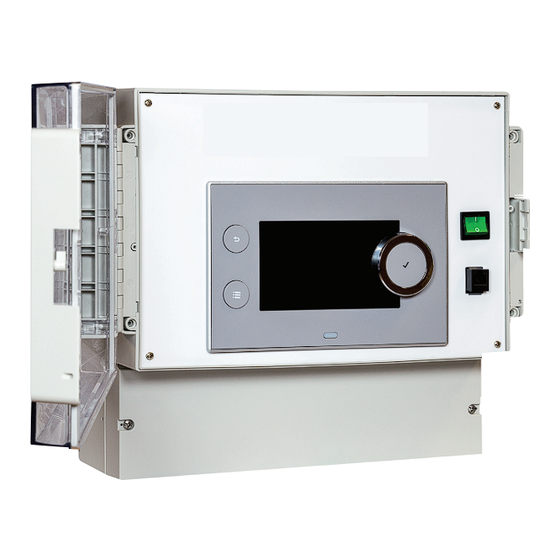
Page 10: Description Of The Product
4 Description of the product Description of the product General description The VM Diematic Evolution box can be used as an extension box to increase the number of secondary zones that are controlled, including the domestic hot water and the swimming pool. - Page 11 4 Description of the product Fig.5 12 11 10 1 Room temperature sensor - circuit A 14 Three-way valve - circuit A 2 Room temperature sensor - circuit B 15 Pump and safety thermostat - circuit B 3 Room temperature sensor - circuit C 16 3-way valve - circuit B 4 Programmable and 0 - 10 V input 17 Domestic hot water tank pump...
-
Page 12: Description Of The Cb-05 Connection Pcb
4 Description of the product Circuit A Circuit B Circuit C AUX circuit Domestic hot wa (with AD249 op (with AD249 op ter circuit tion) tion) Domestic hot water produc tion Domestic hot water produc tion, electric only Stratified tank (2 sensors) Deactivation 4.3.2 Description of the CB–05 connection PCB... - Page 13 4 Description of the product Description Package Mod-Bus connection cable, 1.5 m AD124 Mod-Bus connection cable, 12 m AD134 Mod-Bus connection cable, 40 m DB119 PCB + sensor for three-way valve AD249 Domestic hot water sensor and TAS AD212 Flow sensor after valve AD199 Sensor for buffer tank or cascade flow AD250...
-
Page 14: Before Installation
5 Before installation Before installation Installation regulations Caution The appliance must be installed and maintained by a certified professional in accordance with prevailing statutory texts and codes of practice. Electrical power supply Tab.3 Electrical information Power supply voltage 230 V AC/50 Hz Power supply Single phase Fuse on the PCB... -
Page 15: Position Of The Appliance
5 Before installation 5.3.2 Position of the appliance Caution When installing appliances, respect the IP21 protection rating. Fig.8 Allow sufficient space around the housing to allow access and facilitate maintenance. The minimum recommended dimensions are shown in the illustration in mm. As standard, the control panel access door opens to the left. -
Page 16: Connecting Diagrams And Configuration
6 Connecting diagrams and configuration Connecting diagrams and configuration Factory settings for circuits In the factory, the different circuits are configured as indicated in the table. You can modify this configuration and adapt it to the needs of your installation. Three installation types are described here to provide a guide. Tab.4 Circuit Circuit type... -
Page 17: Electrical Connections
6 Connecting diagrams and configuration Fig.9 AD 199 MASTER AD249 AD 309 S-BUS CIRCA CIRCB CIRCC AD212 112c AD212 AD212 °C °C B... 2xAD 199 SA19 230V/50Hz MW-4000221-2 FOLLOWER 4 Pressure gauge 29 Pressure reducer 7 Automatic air vent 32 Domestic hot water circulation loop pump 9 Isolation valve 33a Domestic hot water temperature sensor, high 10 Three-way mixing valve... -
Page 18: System Configuration
6 Connecting diagrams and configuration Fig.10 CIRCA CIRCB CIRCC 8 99 3 17 4 13 10 5 MW-1001113-2 1. Make the connections on the master box. Tab.6 Domestic hot water circulation loop pump DHW booster pump Domestic hot water temperature sensor, high position Domestic hot water temperature sensor, low position Flow temperature sensor after mixing valve Pump for heating circuit with mixing valve... -
Page 19: Cascade Of 3 Generators, 3 Heating Circuits And 1 Dhw Circuit Controlled By Vm Diematic Evolution
6 Connecting diagrams and configuration 8. Configure the parameters for the following components: Tab.8 Component Access Parameter Code Adjustment required Cascade Analogue input > Adv. Sets the general configuration of EP037 System (cascade) Parameters the sensor input 2 Recirculating pump AUX Functionality of the zone CP024 Time Program... -
Page 20: Electrical Connections
6 Connecting diagrams and configuration Fig.11 2x AD199 MASTER AD249 CIRCA CIRCB CIRCC AD212 AD212 AD 309 S-BUS AD250 B... FOLLOWER IniControl 2 IniControl 2 IniControl 2 AD308 AD308 S-BUS S-BUS SA21 MW-4000219-2 4 Pressure gauge 29 Pressure reducer 7 Automatic air vent 32 Domestic hot water circulation loop pump 9 Isolation valve 33a Domestic hot water temperature sensor, high... -
Page 21: System Configuration
6 Connecting diagrams and configuration Fig.12 CIRCA CIRCB CIRCC 16 14 15 10 5 MW-1001112-1 1. Make the connections on the master box. Tab.10 Domestic hot water circulation loop pump DHW booster pump Domestic hot water temperature sensor, high position Domestic hot water temperature sensor, low position Flow temperature sensor after mixing valve Pump for heating circuit with mixing valve... -
Page 22: Cascade Of 2 Generators + Addition Of 3 Heating Circuits + 1 Dhw Circuit Controlled By Vm Diematic Evolution
6 Connecting diagrams and configuration 8. Configure the parameters for the following components: Tab.12 Component Access Parameter Code Adjustment required Cascade Analogue input > Adv. Sets the general configuration of EP037 System (cascade) Parameters the sensor input 2 Recirculating pump AUX Functionality of the zone CP024 Time Program... - Page 23 6 Connecting diagrams and configuration Fig.13 2x AD199 FOLLOWER AD249 AD134 MODBUS CIRCA CIRCB CIRCC AD212 AD212 B... Diematic iSystem Diematic iSystem Diematic iSystem iniControl AD199 230 V 230 V 50Hz 50Hz AD249 MASTER 230 V 50Hz SA33 MW-4000220-2 4 Pressure gauge 29 Pressure reducer 7 Automatic air vent 32 Domestic hot water recirculating pump...
-
Page 24: Electrical Connections
6 Connecting diagrams and configuration 6.4.1 Electrical connections For this configuration, the AD249 and AD134 packages should be installed for the Mod-BUS connection. Fig.14 CIRCA CIRCB CIRCC 16 14 8 99 4 15 10 5 MW-1001114-1 1. Make the connections on the slave box. Tab.14 Domestic hot water circulation loop pump DHW booster pump... - Page 25 6 Connecting diagrams and configuration 5. Check the following parameters: Tab.15 Code Description Adjustment required NP006 Cascade Type Traditional NP009 CascInterStageTime NP011 CascadeTypeAlgo Temperature 6. Press the key. 7. Select Installation Setup. 8. Configure the parameters for the following components: Tab.16 Component Access...
-
Page 26: Installer Instructions
7 Installer instructions Installer instructions Reversing the opening direction of the box door The access door is delivered from the factory to open to the left It is possible to reverse the opening direction of the door: 1. With the door open, use a screwdriver to unclip the door and the support. -
Page 27: Fit The Housing To The Wall
7 Installer instructions Fit the housing to the wall Fig.17 1. Drill three holes in the wall and insert the dowels. 2. Fit the upper screw, leaving 3 mm between the wall and the head of the screw. 3. Hang the housing on the wall on the locating screw. 4. -
Page 28: Selecting The Operating Mode
7.5.1 Using the VM Diematic Evolution box as an extension In this case, the VM Diematic Evolution box is connected in a network with one or more generators equipped with a Inicontrol-2 and Diematic Evolution control panel (with the option of S-Bus network connection):... -
Page 29: Configuring The Installation
7 Installer instructions possible to have from 1 to 20 Diematic VM iSystem or VM Diematic Evolution boxes and 1 to 10 generators equipped with a Diematic 4 or Diematic Evolution control panel. Configuring the installation 7.6.1 Control panel description Description of the user interface Fig.23 1 Rotary knob to select a menu or setting... -
Page 30: Definition Of Zone And Activity
7 Installer instructions 7.6.2 Definition of zone and activity Zone Fig.25 Term given to the different hydraulic circuits CIRCA, CIRCB, ..It indicates several rooms served by the same circuit. Tab.18 Example Zone Factory-set name Zone 1 CIRCA Zone 2 Zone 1 Zone 2 CIRCB... -
Page 31: Personalising The Name And Symbol For A Zone
7 Installer instructions 1. Press the key. 2. Select System Settings. 3. Select Set Heating Activity Names. 4. Select the activity you want to change. 5. Change the name of the activity (10 characters max.). Tab.21 Factory setting Customer setting Activity 1: Sleep Activity 2:... -
Page 32: Commissioning
8 Commissioning Commissioning Initial commissioning (or after an update) 1. Switch the VM Diematic Evolution housing on using the on/off switch. The Select country and language used for translation parameter appears. 2. Select Select country and Select language and confirm. -
Page 33: Changing The Room Temperature Temporarily
8 Commissioning 8.3.3 Changing the room temperature temporarily Regardless of the operating mode selected for a zone, it is possible to modify the room temperature for a defined period. Once this time has elapsed, the selected operating mode will restart. 1. -
Page 34: Forcing Domestic Hot Water Production (Override)
8 Commissioning 2. Select the desired operating mode: Tab.24 Mode Description Selection of a timer programme Scheduling The domestic hot water temperature remains at the comfort temperature Manual permanently The production of domestic hot water is forced at the comfort temperature Hot water boost for a defined duration The domestic hot water temperature is reduced during an absence period... -
Page 35: Activating The Holiday Program
8 Commissioning Fig.28 2. Select Zone configuration > DHW Schedule. 3. Select the programme to be modified. 14 : 23 Zo... Zone setup... DHW1: DHW Schedule The programmed activities for Sunday are displayed. Sunday The last activity of the day remains active until the first activity of the 6:00 Comfort 55.0°C... -
Page 36: Setting The Heating Curve
8 Commissioning Fig.29 3. Set the following parameters: ° C Parameters Description Zone screed drying Number of days of drying (1) ScreedStartTemp Drying start temperature (2) ScreedStopTemp Drying end temperature (3) The screed drying program will start immediately and continue for the 00:00 00:00 00:00... -
Page 37: Cascade Operation
8 Commissioning 8.10 Cascade operation The DIEMATIC Evolution control panel installed as master is able to control up to seven generators in cascade. The system sensor is connected to the master generator. All the generators in the cascade are connected by an S-BUS cable. The generators are automatically numbered: Number 1 = master generator Number 2 = not assigned... -
Page 38: Managing A Parallel Cascade
8 Commissioning Tab.29 Factory settings for management parameters for a traditional cascade Code Description EEC-01 NP006 Cascade Type Traditional NP009 CascInterStageTime NP011 CascadeTypeAlgo Temperature 8.10.2 Managing a parallel cascade Fig.32 Caution Parallel mode is not suitable for the cascades of oil generators connected to a single flue gas pipe (for start-up reasons). -
Page 39: Menu Tree
9 Menu tree Menu tree Level 1 menus accessible with the button: Level 1 menu Installation Setup Commissioning Menu Advanced Service Menu Error History System Settings Version Information Menu - Installation Setup Tab.31 Installation Setup Level 2 menu Level 3 menu CIRCA Short temperature change OperatingZoneMode... -
Page 40: Menu - Advanced Service Menu
9 Menu tree Level 2 menu Level 3 menu Zone Function Zone friendly Name Icon display zone Parameters, counters, signals (see Tab.38, page 42) Zone Name Short Parent device Outside temp Summer Winter Force summer mode Frost min out temp Out sensor detected (see Tab.39, page 42) Parameters, counters, signals... -
Page 41: Menu - Version Information
9 Menu tree Level 2 menu Level 3 menu Installer Details Set Heating Activity Names Set Screen Brightness Set click sound Firmware Update License Information Menu - Version Information Tab.35 Version Information Level 2 menu Level 3 menu MK3 (DIEMATIC Evolution), EEC-01 (see Tab.46, page 44) Sub-menus - Parameters, counters, signals Tab.36... - Page 42 9 Menu tree Tab.37 Installation Setup > DHW > Parameters, counters, signals Parameters Signals Counters Adv. Parameters Adv. Signals MaxZoneTFlowSetpo Zone Tflow /DHW Zone pump run hours Zone Power setpoint Status pump zone temp Zone Nbr pump starts Zone PWM Pump Zone RU present Zone Function ZonePumpSpeed...
- Page 43 9 Menu tree Tab.40 Disabled buffer tank Installation Setup > Disabled buffer tank > Parameters, counters, signals Parameters Counters Signals Type Buffer Tank Buffer Tout BTankSelectOutSensor Buff Tank HC Strat. Meas Btank temp 1 Stp Buffertank Heat Meas Btank temp 2 Setp Buffertank Cool Btank OnOff input HD Buffer Tank Slope...
- Page 44 9 Menu tree Tab.45 Status information Installation Setup > Status information Parameters Signals Status relay func. Status contact 1 1 Tab.46 Version Information Installation Setup > Version Information Appliance information EEC-01 Factory location Complete version Complete version Appliance type Manufacturer code Manufacturer code Appliance hardware version Hardware version...
-
Page 45: 10 Maintaining The Installation
10 Maintaining the installation 10 Maintaining the installation 10.1 Viewing the service notifications When a service notification appears on the display, you can view the details of the notification. 1. Select the Maintenance icon. Information about maintenance is displayed (cannot be modified). 10.2 Resetting or re-establishing the parameters. -
Page 46: 11 Troubleshooting
11 Troubleshooting 11 Troubleshooting 11.1 Error codes If an error occurs, the control panel displays a message and a corresponding code. The control panel status LED flashes and/or is displayed in red. The control panel can display three types of error codes: Type of code Description Colour of the error icon... -
Page 47: 12 Warranty
12 Warranty 12 Warranty 12.1 General We would like to thank you for buying one of our appliances and for your trust in our product. In order to ensure continued safe and efficient operation, we recommend that the product is regularly inspected and maintained. Your installer and our service department can assist with this. - Page 48 12 Warranty The rights established in European Directive 99/44/EEC, implemented by legal decree No. 24 of 2 February 2002 and published in Official Journal No. 57 of 8 March 2002, remain in force. 7703592 - v02 - 14062018...
-
Page 49: 13 Spare Parts
13 Spare parts 13 Spare parts 13.1 General Only replace defective or worn parts of the VM Diematic Evolution housing with original parts or recommended parts. Information about available parts can be found via the website for professionals. Fig.33 http://pieces.dedietrich-thermique.fr... - Page 50 13 Spare parts Markers Reference Description 95315406 PE 11 lock nut 7671840 RJ11 socket 7676390 VM white front panel 96493510 PMC46/01 earth POP rivet 7672069 VM box 7676108 VM power cable 7676161 END connector 7676221 Cable RJ11 0.3 m 7618888 Traction arrester device 7610590 EJOT WN 5451 25X15 screw...
- Page 51 © Copyright All technical and technological information contained in these technical instructions, as well as any drawings and technical descriptions supplied, remain our property and shall not be multiplied without our prior consent in writing. Subject to alterations.
- Page 52 57, rue de la Gare - F-67580 Mertzwiller SERVICE CONSOMMATEURS 03 88 80 27 00 0,15 € / min 0 825 120 520 03 88 80 27 99 www.dedietrich-thermique.fr 000 «БДP T » VAN MARCKE 129164, Россия, г. Москва Weggevoerdenlaan 5 Зубарев...
Need help?
Do you have a question about the VM Diematic Evolution and is the answer not in the manual?
Questions and answers