Advertisement
Quick Links
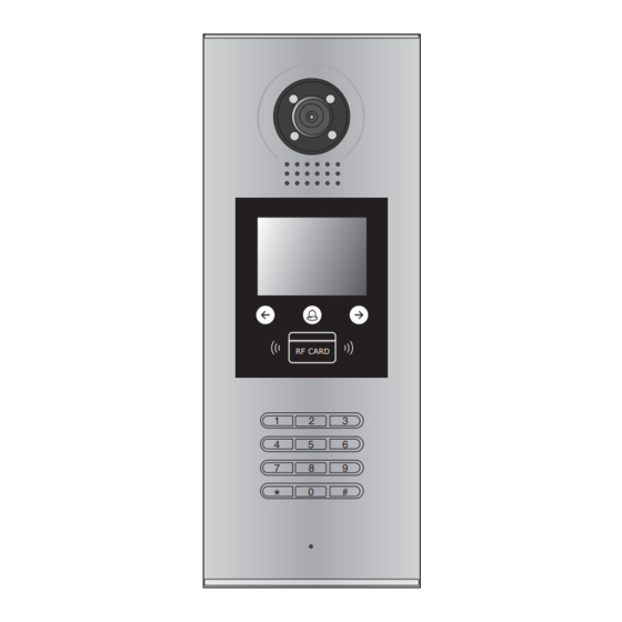
DMR18S DOOR STATION
DMR21 DOOR STATION
DT-BDU BUS AMPLIFIER
DT SYSTEM TEST MANUAL
2-wire Intercom System
.................................................2
....................................................3
..................................................12
CONTENTS
RF CARD
1
2
3
4
5
6
7
8
9
0
#
*
RF CARD
Advertisement

Related Manuals for V-TEK 2 easy DMR18S


Summary of Contents for V-TEK 2 easy DMR18S
- Page 1 DT SYSTEM TEST MANUAL 2-wire Intercom System CONTENTS ..........2 DMR18S DOOR STATION ............3 DMR21 DOOR STATION ..........12 DT-BDU BUS AMPLIFIER RF CARD RF CARD...
- Page 2 4.Work Mode: 32 apartments mode; DT- DJ mode; DMR18S DOOR STATION Router mode; Gateway mode 1. Basic function: Calling; Conversation; Unlock 32 apartments mode: Direct dial monitor address on keyboard, and press talk button on The 32 Apartments mode is applied in a small capacity system, monitor and conversation, press unlock button to unlock.
- Page 3 Router Mode: DMR21 DOOR STATION The Router Mode is used for the big capacity system which has plen- ty of apartments for blocks with BDU unit. The namelist can be updat- 1. Basic function: ed by SD Card or DT-Config (More details refer to Update Namelist Section).
- Page 4 • Note: Key A and key B can not be seen on the panel,they are cryptic. Tune Volume Setting Normally,key A and key B are not activated. To activate the buttons, When the door station with Camera Module is in standby. just set the DIP6 to ON.
- Page 5 2) TFT Module: Parts and functions Mounting screw 3.5 inch TFT screen • Conversation Touch sensor button This is the user interface of conversation process. The conversation time will be recorded. Press * (Keypad Module) to cancel the call. Functions •...
- Page 6 3) Keypad Module: • The example is set as cancel button and # as confirm button,please refer to */# function setting Parts and functions for detail information. • Forbid to slide to touch the digital keypad,it may cause mistaken key,the correct operation is using Mounting your finger to press the digital you desired.
- Page 7 Input the master code. Beep+, Beep (Default: [ ] +[#] ) 1.Reset all settings 2.Setting the master code 3.Setting the key 4.Setting the illumination time unlock time (Default 1234) (Default 10s) (Default 1s) Input the setting code. Input the setting code. Input the setting code.
- Page 8 Input the master code. Beep+, Beep (Default: [ ] +[#]) 5.Setting the unlock mode 6.Setting operation tone 7.Reset code setting 8. &# function setting (Default 0(opened)) (Default ON) (Default Normal) Input the setting code. Input the setting code. Input the setting code. Input the setting code.
- Page 9 Input the master code. Beep+, Beep (Default: [ ] +[#]) 9. Call tone setting 10.Interference resistant 11.SPK volume adjust 12.Night light level grade setting setting setting (Default enable) (Default 2) (Default:4) (Default 4) Input the setting code. Input the setting code. Input the setting code.
- Page 10 Input the master code. Beep+, Beep (Default: [ ]+[#] ) 16.Setting the code 17.Setting the code 18.Setting the code 19.Setting the code forTemporary1 forTemporary2 for user group1 for user group2 20~59 60~99 Input the setting code. Input the setting code. Input the setting code.
- Page 11 Input the room number you need to set (0 is default). Show User 4) ID Module: Cards, it will sound “BP+”, and the Talk indicator blinks one time. (You can continuously show User Cards). Parts and functions Mounting screw Show the MASTER CARD ADD to exit out Add User Card Setting, Swiping card area it will sound “BP,BP+”, and all indicators are turned off.
- Page 12 DT-BDU BUS AMPLIFIER Wiring diagram: The detail settings of DIP are as follows: 1 2 3 4 5 6 Bit State Description Set to the Repeater mode. 3 4 5 6 BUS(IM) BUS(DS) Set to the Router mode. Bit-1~Bit-2 3 4 5 6 Set to the Gateway mode.
- Page 13 Wiring diagram: Wiring diagram: BUS(IM) BUS(DS) BUS(IM) BUS(DS) BUS(IM) BUS(DS) BUS(IM) BUS(DS) BUS(IM) BUS(DS) BUS(IM) BUS(DS) Gateway Mode: Enable one building as an independent sub-system (Outdoor station(s) can be connect). Up to 8 such system are supported within the whole system. The gateway address is equal to the DT-BDU num- ber.
Need help?
Do you have a question about the 2 easy DMR18S and is the answer not in the manual?
Questions and answers