Table of Contents
Advertisement
Quick Links
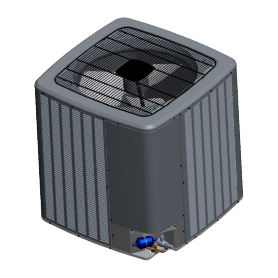
CONDENSING UNIT
*VXC20
Air Conditioning Installation & service reference
Only personnel that have been trained to install, adjust,
service or repair(hereinafter, "service") the equipment
specified in this manual should service the equipment.
The manufacturer will not be responsible for any injury
or property damage arising from improper service or
service procedures. If you service this unit, you assume
responsibility for any injury or property damage which may
result. In addition, in jurisdictions that require one or more
licenses to service the equipment specified in this manual,
only licensed personnel should service the equipment.
Improper installation, adjustment, servicing or repair of
the equipment specified in this manual, or attempting to
install, adjust, service or repair the equipment specified in
this manual without proper training may result in product
damage, property damage, personal injury or death.
"Proper sizing and installation of equipment is critical to achieve optimal performance. Split system
air conditioners and heat pumps must be matched with appropriate coil components to meet ENERGY
STAR criteria. Ask your contractor for details or visit www.energystar.gov.
IMPORTANT – This product has been designed and manufactured to meet ENERGY STAR criteria for
energy efficiency when matched with appropriate coil components. However,
proper refrigerant charge and proper air flow are critical to achieve rated capacity and
efficiency. Installation of this product should follow the manufacturer's refrigerant charging and air
flow instructions. Failure to confirm proper charge and airflow may reduce
energy efficiency and shorten equipment life."
IOG-4014A
07/2020
WARNING
19001 Kermier Rd. Waller, Tx 77484
www.goodmanmfg.com•www.amana-hac.com
© 2020 Goodman Manufacturing Company, L.P.
is a registered trademark of Maytag Corporation or its related companies and is used under license. All rights
IMPORTANT SAFETY INSTRUCTIONS
The following symbols and labels are used throughout
this manual to indicate immediate or potential safety
hazards. It is the owner's and installer's responsibility to
read and comply with all safety information and instructions
accompanying these symbols. Failure to heed safety
information increases the risk of personal injury, property
damage, and/or product damage.
High Voltage!
Disconnect all power before servicing or
installing this unit. Multiple power sources may
be present. Failure to do so may cause property
damage, personal injury or death.
Do not wash the condensing unit with excessive water. An
electric shock or fire could result.
FOR CALIFORNIA CONSUMERS
Cancer and Reproductive Harm -
www.P65Warnings.ca.gov
reserved.
WARNING
CAUTION
PROP 65 WARNING
WARNING
0140M00517-A
Advertisement
Table of Contents

Related Manuals for Amana VXC20 Series


Summary of Contents for Amana VXC20 Series
-
Page 1: Important Safety Instructions
Failure to confirm proper charge and airflow may reduce energy efficiency and shorten equipment life.” 19001 Kermier Rd. Waller, Tx 77484 www.goodmanmfg.com•www.amana-hac.com © 2020 Goodman Manufacturing Company, L.P. IOG-4014A is a registered trademark of Maytag Corporation or its related companies and is used under license. All rights 07/2020 reserved. -
Page 2: Table Of Contents
INDEX Important Safety Instructions ........1 Shipping Inspection ............3 Codes & Regulations ............3 Features ................3 Installation Clearances ..........3 Rooftop Installations ...........4 Safe Refrigerant Handling ..........4 Refrigerant Lines ............5 Leak Testing (Nitrogen Or Nitrogen-Traced) ..7 System Start-Up Procedure .........7 Electrical Connections ..........8 Coolcloud™... -
Page 3: Shipping Inspection
Specification connectivity with the CoolCloud™ app. sheets can be found at www.goodmanmfg.com for Goodman brand products or www.amana-hac.com for Due to components using inverter technology, the air ® Amana brand products. Within the website, please select conditioner will not function properly if used with a non- ®... -
Page 4: Rooftop Installations
Another important consideration in selecting a location for When selecting an installation location, keep sufficient the unit(s) is the angle to obstructions. Either side adjacent distance from the air conditioner unit and wiring to radios, the valves can be placed toward the structure provided the personal computers, stereos, etc., as shown in the side away from the structure maintains minimum service following figure. -
Page 5: Refrigerant Lines
Where possible, drain as much residual compressor WARNING oil from existing systems, lines, and traps; pay close attention to low areas where oil may collect. NOTE: O AVOID POSSIBLE EXPLOSION If changing refrigerant, the indoor coil and metering •N EVER APPLY FLAME OR STEAM TO A REFRIGERANT CYLINDER F YOU device must be replaced. -
Page 7: Leak Testing (Nitrogen Or Nitrogen-Traced)
LEAK TESTING Refrigerant Line Connections (NITROGEN OR NITROGEN-TRACED) IMPORTANT To avoid overheating the service valve, TXV, sensor or filter WARNING drier while brazing, wrap the component with a wet rag, or use a thermal heat trap compound. Be sure to follow O AVOID THE RISK OF FIRE OR EXPLOSION NEVER USE OXYGEN HIGH... -
Page 8: Electrical Connections
ELECTRICAL CONNECTIONS CAUTION AHRI SE REFRIGERANT CERTIFIED TO STANDARDS SED REFRIGERANT WARNING MAY CAUSE COMPRESSOR DAMAGE IS NOT COVERED UNDER HIGH VOLTAGE! WARRANTY OST PORTABLE MACHINES CANNOT CLEAN USED AHRI ISCONNECT POWER BEFORE SERVICING REFRIGERANT TO MEET STANDARDS ULTIPLE POWER SOURCES MAY BE PRESENT AILURE TO DO SO MAY CAUSE PROPERTY DAMAGE PERSONAL... - Page 9 Local codes often require a disconnect switch located near the unit; do not install the switch on the unit. Overcurrent Protection The inverter control system software provides sufficient time delay to protect from overcurrent conditions and permit the compressor and fan motors to adjust their rotational speed.
- Page 10 System Wiring Unit Tonnage Actual Line Set 2-Ton 3-Ton 4-Ton 5-Ton Step 1. Calculate Refrigerant Charge Based on Length (ft.) Total Refrigerant (oz.) Line Set Length 15 (Factory Charge) The condenser unit is shipped with a predetermined factory charge level as shown below. For longer line sets greater than 15 feet, add 0.6 ounces of refrigerant per foot.
-
Page 11: Coolcloud™ Hvac Phone Application
Step 3. System Start-up Test CAUTION POSSIBLE REFRIGERANT LEAK! NOTICE O AVOID A POSSIBLE REFRIGERANT LEAK OPEN THE SERVICE VALVES 1/8” UNTIL THE TOP OF THE STEM IS FROM THE RETAINER On initial power start-up, the outdoor unit will display code E11, signaling that initial SYSTEM test must be run. - Page 12 Step 4. CHARGE MODE SUBCOOLING = (SAT. LIQUID TEMP.) - (LIQUID LINE TEMP.) CHARGE MODE allows for charging of the system. SUPERHEAT = (SUCT. LINE TEMP.) - (SAT. SUCT. TEMP.) System operates for a duration of approximately one hour Charging Table while the equipment runs at full capacity.
- Page 13 NOTICE ATTENTION INSTALLER - IMPORTANT NOTICE! Please read carefully before installing this unit. ADJUST THE CHARGE BASED ON SUCTION PRESSURE UNLESS THERE IS A GROSS UNDERCHARGE • Do not attach any wires to the R & C Terminals on the Condensing Unit, as they are not needed for inverter unit setup.
-
Page 14: Comfortbridge™ System
COMFORTBRIDGE™ SYSTEM Dehumidification Dehumidification requires a thermostat capable of reading the indoor humidity level and allowing the user to set a Overview dehumidification target. The ComfortBridge based inverter heating and air conditioning system uses an indoor unit and outdoor unit The thermostat controls the humidity level of digitally communicating with one another via a two-way the conditioned space using the cooling system. - Page 15 Sensor Data • Profile D (default) ramps up to 50% of the demand The following sensor values will be displayed: for 1/2 minute, then ramps to 82% of the full cooling • Outdoor Temperature demand airflow and operates there for approximately •...
- Page 16 In setting “C” the system runs fixed at 100% compressor and airflow. See Figure 1. NOTE: In high humidity environments, sweating on supply ducts, cased coils or air handler cabinets can become an issue in Enhanced Dehumidification operation. It is strongly recommended covering then with 2”...
-
Page 17: Air Conditioner Advanced Feature Menu
Air Conditioner Advanced Feature Mentu AIR CONDITIONER(AC) / FAULT CODE HISTORY SUBMENU ITEM INDICATION/USER MODIFIABLE OPTIONS COMMENTS (The Active and History Fault codes are displayed.) Active fault code and up to 6 fault code histories. ACTIVE (The Active Fault codes are displayed.) Active fault code only. - Page 18 Air Conditioner Advanced Feature Menu AIR CONDITIONER(AC) / DEVICE SETTING SUBMENU ITEM INDICATION(Units) COMMENTS BOOST MODE is ON by default. See BOOST MODE BOOST MODE ENABLE OFF or ON section of this manual for more details. If enabled, when the ambient outdoor temperature is greater than this selected value, boost mode will be operational.
-
Page 19: Wiring Diagrams
Wiring Diagram - 2-3 Tons *VXC200241**; *VXC200361** Wiring is subject to change. Always refer to the wiring diagram on the unit for the most up-to-date wiring. - Page 20 Wiring Diagram - 4 Tons *VXC200481** Wiring is subject to change. Always refer to the wiring diagram on the unit for the most up-to-date wiring.
- Page 21 Wiring Diagram - 5 Tons *VXC200601** Wiring is subject to change. Always refer to the wiring diagram on the unit for the most up-to-date wiring.
-
Page 22: Testing Capacitor Resistance
Testing Capacitor Resistance WARNING VOID CONTACT WITH THE CHARGED AREA •N EVER TOUCH THE CHARGED AREA BEFORE CONFIRMING THAT THE RESIDUAL VOLTAGE IS VOLTS OR LESS 1. S HUT DOWN THE POWER AND LEAVE THE CONTROL BOX FOR MINUTES 2. M AKE SURE TO TOUCH THE ARTH GROUND TERMINAL TO RELEASE THE STATIC ELECTRICITY FROM YOUR BODY TO PREVENT... - Page 23 Testing Capacitor Resistance WARNING VOID CONTACT WITH THE CHARGED AREA •N EVER TOUCH THE CHARGED AREA BEFORE CONFIRMING THAT THE RESIDUAL VOLTAGE IS VOLTS OR LESS 1. S HUT DOWN THE POWER AND LEAVE THE CONTROL BOX FOR MINUTES 2. M AKE SURE TO TOUCH THE ARTH GROUND TERMINAL TO RELEASE THE STATIC ELECTRICITY FROM YOUR BODY TO PREVENT...
- Page 24 Testing Capacitor Resistance WARNING VOID CONTACT WITH THE CHARGED AREA •N EVER TOUCH THE CHARGED AREA BEFORE CONFIRMING THAT THE RESIDUAL VOLTAGE IS VOLTS OR LESS 1. S HUT DOWN THE POWER AND LEAVE THE CONTROL BOX FOR MINUTES 2. M AKE SURE TO TOUCH THE ARTH GROUND TERMINAL TO RELEASE THE STATIC ELECTRICITY FROM YOUR BODY TO PREVENT...
- Page 25 Outdoor normal temperature operating range: 67-115°F / Indoor normal temperature operating range: 65-85°F WARNING VOID CONTACT WITH THE CHARGED AREA •N EVER TOUCH THE CHARGED AREA BEFORE CONFIRMING THAT THE RESIDUAL VOLTAGE IS VOLTS OR LESS 1. S HUT DOWN THE POWER AND LEAVE THE CONTROL BOX FOR MINUTES 2.
-
Page 26: Troubleshooting
Troubleshooting (*1) This message is displayed when using the CTK04 thermostat... - Page 27 Troubleshooting (*1) This message is displayed when using the CTK04 thermostat...
- Page 28 Troubleshooting (*1) This message is displayed when using the CTK04 thermostat (*2) Network communication error (Refer to “NETWORK TROUBLESHOOTING”)
- Page 29 Troubleshooting (*1) This message is displayed when using the CTK04 thermostat...
- Page 30 Network Troubleshooting 3. Perform continuity check on wires to make sure cable If a network communication error code has occurred, use is OK. Replace the cable if necessary. the following steps to help troubleshoot the system. (For 4. Change both dip switches of DS1 on the outdoor unit network communication error codes, refer to the table control board to the opposite position.
-
Page 31: Setting Mode Display
Setting The Mode Display MODE DISPLAY INTRODUCTION A 3-digit display is provided on the printed circuit board (PCB) as a backup tool to the thermostat for reading faults, fault history, monitoring and setting up the unit. Follow the information provided in this section to learn how to use the mode display. DISPLAY The display consists of 3 digits. - Page 32 Setting The Mode Display NAVIGATING THROUGH THE DISPLAY SCREENS SCREEN The home or default screen on the display. This shows the most recent fault. SCREEN 1 To access, hold the RECALL button for 5 seconds at screen 0. SCREEN 2 To access, hold the RECALL button for 5 seconds at screen 1.
- Page 33 Setting The Mode Display FAULT CODE HISTORY NAVIGATION < SCREEN 1> This mode will allow the user to see the six most recent system faults. For a list of the fault codes, please see the TROUBLESHOOTING tables in this document. <...
- Page 34 Setting The Mode Display MONITORING MODE NAVIGATION < SCREEN 0 > < SCR EEN 2 > This screen allows the user to monitor system variables as shown in the tables at the end of this section. Blink interval: < SCREEN 1 > 0.4 sec.
- Page 35 Setting The Mode Display SETTINGS MODE 1 NAVIGATION < SCREEN 3 > < SCREEN 0 > Setting Mode 1 allows the user to adjust system settings as shown in the tables at the end of this section. Blink interval: < SCREEN 2 > 0.4 sec.
- Page 36 Setting The Mode Display SETTINGS MODE 2 < SCREEN 4 > < SCREEN 0 > Setting Mode 2 allows the user to change system settings. See table in back of this section. Blink interval: 0.4 sec. On - 0.4 sec. Off <...
-
Page 37: 7-Segment Display
7-Segment Display SCREEN 0 (Display FAULT CODE) Setting Contents Notes Fault code (present) SCREEN 1 (Display FAULT CODES) Setting Contents Notes Fault code (latest) Latest Fault code (2nd) Fault code (3rd) Fault code (4th) Fault code (5th) Fault code (6th) SCREEN 2 (MONITOR MODE) Setting Contents... - Page 38 7-Segment Display Screen 4 (Setting Mode 2) Setting No. Contents Setting Installer/Serviceman Notes 0:30 min 1: 60min. Maximum Defrost Interval 2: 90min. 3: 120min. Set Maximum Current Future Use 0: Same Level Vertical Rise 1: Outdoor Lower 2: Indoor Lower System Verification Test (System Test) 0: ON 1: OFF...
-
Page 42: Ctk04 Addendum
CTK04 ADDENDUM Two Wire Outdoor, Four-Wire Indoor Wiring Low voltage wiring consists of two wires between the indoor unit and condensing unit and four wires between the indoor unit and thermostat. The required wires are data lines 1 and 2, “R” (24 VAC hot) and “C” (24 VAC common). Never connect the power wiring to communication terminal (1, 2, R, C). - Page 43 System Start-up Test NOTICE N INITIAL POWER START THE OUTDOOR UNIT WILL DISPLAY CODE E11, SYSTEM SIGNALING THAT INITIAL TEST MUST BE RUN OLLOW ™ OMFORT SETUP SCREEN TO ENTER APPLICATION UNIQUE INFORMATION OMFORT ET THERMOSTAT MANUAL FOR DETAILED INFORMATION A system test is now required to check the equipment settings and functionality.
- Page 44 4. From the MENU screen, scroll down and select COMFORTNET™ USER MENU. 5. Enter Installer password. (The password is the Date Code located on the thermostat and is available by entering the EQUIPMENT STATUS menu and scrolling to the bottom.) 6.
- Page 45 8. Next, scroll down and select EQUIP TEST. 9. Select SYSTEM TEST. 10. Select ON to run the SYSTEM TEST. Press DONE to initiate test. 11. Allow the system test to run for its duration (5-15 minutes). EQUIP TEST SCREEN will show the system test is ON once selected.
- Page 46 12. Press Previous Menu button and navigate to HOME screen and allow test to finish. The display similar to the one at the right will be displayed after SYSTEM TEST completes. Test is complete only when CODE 11 notice clears from BOTH the thermostat display AND the seven segment LED display on the outdoor unit.
- Page 47 3. Enter Installer password. (The password is the Date Code located on the thermostat and is available by entering the EQUIPMENT STATUS menu and scrolling to the bottom). 4. Select YES to continue. 5. Select Air Conditioner. 6. Select MAINTENANCE.
- Page 48 7. Select CHARGE MODE. 8. Select ON. Press DONE to initiate CHARGE mode. (System will then run for 1 hour and either return to cooling mode if the thermostat is set for COOL mode, or stop if the thermostat is set for FAN or HEAT mode.) If charging is not complete after 1 hour, repeat 7.
- Page 49 Adjust Refrigerant level c. If subcooling is low and superheat is high, add Using service equipment, add or recover refrigerant charge to rise subcooling to 8°F ± 1°F, then check according to the calculation in Step 1. Allow system to superheat.
- Page 50 Air Conditioner with Outdoor Temperature SATURATED SUCTION PRESSURE SATURATED LIQUID PRESSURE Lockouts TEMPERATURE CHART TEMPERATURE CHART SUCTION PRESSURE R-410A LIQUID PRESSURE R-410A It is recommended to set the outdoor temperature lockouts °F °F PSIG PSIG during the initial thermostat set up. Compressor lockout temperature will enable the compressor to be turned off and switch heating source from refrigeration to auxiliary/secondary heating under low outdoor ambient conditions.
- Page 51 3. Enter Installer password if known. The password is the thermostat date code and can obtained by selecting the red Cancel button and selecting the Dealer information button. Once recorded, click the green OK button and return to the previous step. 4.
- Page 52 7. BOOST MD turns BOOST MODE OFF or ON. BOOST MODE is on by default. Previous SET MAX CURRENT: OFF Menu Outdoor VERTICAL RISE: Help Lower BOOST MD: ON BOOST TEMP: Always On Cancel Help Done 8. BOOST TEMP adjusts the activation temperature from 70° F to 105°...
- Page 53 9. Once satisfied with BOOST MODE adjustments, navigate to the HOME screen by selecting the Previous Menu button three times then selecting HOME. Dehumidification 4. Select YES to continue. 5. Select View / Edit Current Setup. The thermostat reads the indoor humidity level from the 6.
- Page 54 ComfortNet™ System Status Overview This menu displays information about the systems current A ComfortNet inverter heating and air conditioning system status. This menu can be utilized to confirm correct function- uses an indoor unit, outdoor unit and thermostat which digitally ality of the equipment and for troubleshooting purposes.
- Page 55 Maintenance • Profile D (default) ramps up to 50% of the demand for 1/2 minute, then ramps to 82% of the full cooling Pump down and charge modes can be enabled within this demand airflow and operates there for approximately menu.
- Page 56 Cool Run Values Depending on the system configuration, adjusting the maxi- mum compressor RPS (revolutions per second) may be re- quired. Necessary adjustments to the maximum compressor RPS are made through the following sub-menus. Maximum Compressor RPS Range for Cooling Select the range that your maximum compressor RPS falls within.
- Page 59 THIS PAGE IS INTENTIONALLY LEFT BLANK...
- Page 60 You can also scan the QR code on the right for the product brand you purchased to be directed to the Product Registration page. NOTE: Specifications and performance data listed herein are subject to change without notice. Visit our website at www.goodmanmfg.com or www.amana-hac.com for information on: • Products • Parts •...
Need help?
Do you have a question about the VXC20 Series and is the answer not in the manual?
Questions and answers