Neptune Technology R900 Gateway v4 Installation And Maintenance Manual
Hide thumbs
Also See for R900 Gateway v4:
- Installation supplement manual (21 pages) ,
- User manual (68 pages) ,
- Installation & maintenance manual (71 pages)
Table of Contents
Advertisement
Quick Links
Advertisement
Table of Contents
Troubleshooting

Related Manuals for Neptune Technology R900 Gateway v4


Summary of Contents for Neptune Technology R900 Gateway v4
- Page 7 INFRASTRUCTURE ANTENNAS Omnidirectional Carrier Grade Fiberglass Antennas - LMR & Cellular BOA Series PCTEL Heavy-Duty Omnidirectional RoHS Base Station Platform COMPLIANT The PCTEL BOA omnidirectional base station antennas consist of a linear array, encapsulated in a heavy-duty fiberglass radome with a thick-walled 6061-T6 aluminum mounting base. The rugged and robust design makes these antennas ideal for deployment in harsh environments where long term reliability and durability cannot be compromised.
- Page 8 ® R900 Gateway v4 Installation and Maintenance Guide...
- Page 10 ® R900 Gateway v4 Installation and Maintenance Guide...
- Page 11 This manual is an unpublished work and contains the trade secrets and confidential information of Neptune Technology Group Inc., which are not to be divulged to third parties and may not be reproduced or transmitted in whole or part, in any form or by any means, electronic or mechanical for any purpose, without the express written permission of Neptune Technology Group Inc.
-
Page 12: Table Of Contents
Storage ............... . . 13 R900 Gateway v4 Installation and Maintenance Guide... - Page 13 Configuring the Gateway ............35 R900 Gateway v4 Installation and Maintenance Guide...
- Page 14 Contacting Customer Support ............57 R900 Gateway v4 Installation and Maintenance Guide...
- Page 15 Coaxial Cable Lengths for the Gateway ........... . 79 R900 Gateway v4 Installation and Maintenance Guide...
- Page 16 Determining if You Need a Crossover Cable ..........94 Glossary Index R900 Gateway v4 Installation and Maintenance Guide...
- Page 17 Notes: viii R900 Gateway v4 Installation and Maintenance Guide...
- Page 18 Attaching the RF Antenna Cable........... . 33 R900 Gateway v4 Installation and Maintenance Guide...
- Page 19 Cellular Modem Front - Status LEDs ..........85 R900 Gateway v4 Installation and Maintenance Guide...
- Page 20 Crossover Ethernet Cable............94 R900 Gateway v4 Installation and Maintenance Guide...
- Page 21 Figures Notes: R900 Gateway v4 Installation and Maintenance Guide...
- Page 22 Cable Color Code Table ........... . 94 R900 Gateway v4 Installation and Maintenance Guide...
- Page 23 Tables Notes: R900 Gateway v4 Installation and Maintenance Guide...
-
Page 24: About This Guide
About This Guide The R900 Gateway v4 Installation and Maintenance Guide describes how to install, maintain, and troubleshoot the Gateway. This guide also provides information for configuring the cellular modem for the Gateway, installing the solar power unit, and ordering information for necessary cables and accessories. -
Page 25: General Product Overview
This guide is intended for use by installers and is designed to help in the installation process. In addition, this guide contains information on individual components, material specifications, installation site selection, and detailed installation instructions. R900 Gateway v4 Installation and Maintenance Guide... -
Page 26: Determining How To Install The Gateway
RF propagations should be conducted prior to site selection to ensure adequate RF communications. R900 Gateway v4 Installation and Maintenance Guide... -
Page 27: Mounting Configurations
The Gateway allows for a cellular modem or Ethernet connection for back- haul communication. Gateway Stand The Gateway mounted on a stand can be either solar-powered or AC- powered. Refer to Figure 4 for typical stand configuration. Figure 4 Gateway Stand Installation R900 Gateway v4 Installation and Maintenance Guide... -
Page 28: Pole Installation
Zones D and E, then the 220W option is recommended. See Appendix A, "Solar Power Information", on page 59. The kit is mounted on either a 2-in. to 16-in. pole or a stand. R900 Gateway v4 Installation and Maintenance Guide... -
Page 29: Ac Unit
Qty. 13458-000 R900 Gateway v4 - Cellular Modem 13194-001 R900 Gateway v4 Installation and Maintenance Guide SIM card with cellular service account (customer provided) 13147-000 External Cellular Antenna Mounting Kit, optional Accessories are available. Contact your Neptune sales representative for details. -
Page 30: Activating The Cellular Service To The Gateway
After you have completed all the above steps, configure the cellular modem as described in "Configuring the Cellular Modem" on page 83 in Appendix D. R900 Gateway v4 Installation and Maintenance Guide... - Page 31 Overview Notes: R900 Gateway v4 Installation and Maintenance Guide...
-
Page 32: General Installation Information
2 General Installation Information Use the information in this chapter to ensure that you properly prepare for installing R900 Gateway v4 (Gateway) units according to the guidelines provided in this guide. Preparation This section describes the necessary procedures to prepare for the installation of new Gateway units and completed before hardware installation occurs. -
Page 33: Guidelines
(22.8 x 33 x 19 cm) Gateway Stands ROHN Dimensions 5 x 5 ft. square (1.5 x 1.5 m) Height 10 ft. (304.8 cm) Pole Diameter 2.375 in. (72.4 cm) Weight (excluding ballast) 50 lbs. (22.6 kg) R900 Gateway v4 Installation and Maintenance Guide... -
Page 34: Ups Specifications
Short Circuit Current (Isc) 8.5 A Dimensions 26.0 x 58.0 in. (66 x 147.3 cm) Weight 25.4 lbs. (11.5 kg) Mounting Pole mount 2.0 to 16.0 in. diameter (5.08 to 40.64 cm) R900 Gateway v4 Installation and Maintenance Guide... -
Page 35: Battery Enclosure
Manufacturer Sun Xtender Part No. PVX-1040T Voltage Nominal Capacity 104 Ah (C/24 rate) Dimensions 12.0 L x 6.6 W x 8.93 in.H (30.5 x 16.8 x 22.7 cm) Weight 66 lbs. (30 kg) R900 Gateway v4 Installation and Maintenance Guide... -
Page 36: Rf Antenna Specifications
The temperature of the unit should remain between -40° and 185°F (-40° and 85°C). Keep in mind that the Gateway solar unit has an external battery box containing the battery. Storage for more than one year affects product life. R900 Gateway v4 Installation and Maintenance Guide... -
Page 37: Unpacking
Scotch Part No. WK-101 Additional Materials 3M Super 88 black electrical tape Weatherizing coax cable connections Corrosion inhibitor NOCO Company's NCP-2 or Sanchem Apply to battery terminals Inc.'s No-Ox ID Grease “A” for corrosion protection R900 Gateway v4 Installation and Maintenance Guide... -
Page 38: Safety And Preliminary Checks
Always follow your company’s safety practices and installation guidelines when installing your Gateway unit. • Never perform an installation during a lightning storm or under excessively wet conditions. • Use only approved climbing equipment. R900 Gateway v4 Installation and Maintenance Guide... - Page 39 General Installation Information Notes: R900 Gateway v4 Installation and Maintenance Guide...
-
Page 40: Mounting Rf Antenna To A Pole Or Stand
When installing a stand on a rooftop, always install a roof pad between the stand and rooftop to protect roof. See "Ballast Requirements" on page 81 in Appendix C. R900 Gateway v4 Installation and Maintenance Guide... - Page 41 Figure 7 Attaching Coax Cable Weatherize the RF antenna connection using the weatherizing kit that is specified in “Recommended Tools and Materials” on page 14. See Figure 8. Figure 8 Weatherizing RF Antenna R900 Gateway v4 Installation and Maintenance Guide...
-
Page 42: Mounting The Gateway - Solar Configuration
Install the brackets onto the pole using the U-bolts provided. Be sure the U-bolts are spaced 12.75 in. (32.39 cm) apart and face the brackets true south. See Figure 10. Figure 10 Installing Pole Brackets R900 Gateway v4 Installation and Maintenance Guide... - Page 43 Sanchem Inc.’s No-Ox ID Grease “A”, to the battery terminals. Remove the two knockouts in the back of the battery box by tapping them with a flathead screwdriver and hammer. See Figure 11. Figure 12 Battery and Wiring R900 Gateway v4 Installation and Maintenance Guide...
-
Page 44: Attaching The Solar Panel
15º minimum angle and 60º for a maximum tilt angle. See Appendix A, "Solar Power Information", on page 59. Solar panel tilt angle Figure 15 Solar Panel Tilt Angle Tighten all the nuts and bolts. R900 Gateway v4 Installation and Maintenance Guide... -
Page 45: Mounting The Gateway
Wire feed from solar panel Connector hub Figure 18 Back of Battery Box Connect the red PV (+) solar panel positive lead to the red PV (+) wire in the battery box. R900 Gateway v4 Installation and Maintenance Guide... -
Page 46: Wiring The Battery Box
Attach the red (+) wire to the load (+) terminal inside the battery box. Wire feed to Gateway Figure 21 Battery Box Wires Attach the black (-) wire to the load (-) terminal inside the battery box. See Figure 21. R900 Gateway v4 Installation and Maintenance Guide... -
Page 47: Wiring The Gateway
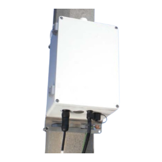
Do not weatherize the power connection. The power connector is IP68-rated and does not require weatherization wrap. Protective Power port Ethernet cover Figure 24 Power Cable Attached to Gateway R900 Gateway v4 Installation and Maintenance Guide... -
Page 48: Securing The Gateway
Evenly distribute the ballast material as illustrated in Figure 25. Secure the stand and ballast material in accordance with local code requirements. Figure 25 Stand with Concrete Block Ballast R900 Gateway v4 Installation and Maintenance Guide... -
Page 49: Activating The Gateway System
Figure 27 Gateway Cover Screws Configuring the Cellular Modem See "Configuring the Cellular Modem" on page 83 in Appendix D. Before you begin, you need an active Cellular account with the carrier of your choice. R900 Gateway v4 Installation and Maintenance Guide... -
Page 50: Configuring The Gateway
MIU readings. However, in areas where the MIU density is high, this green light may remain on constantly to indicate a high volume of MIU RF traffic. Securing the Gateway Secure the Gateway cover with the tamper-resistant T27 Torx Pin-Head tool. R900 Gateway v4 Installation and Maintenance Guide... -
Page 51: Installing A Large Pole Mount System
Mount the RF antenna bracket to the large pole using the two stainless steel Snaplock clamps. See Figure 28. antenna bracket Figure 28 RF Antenna Bracket for a Large Pole R900 Gateway v4 Installation and Maintenance Guide... - Page 52 Attach the coax cable to the base of the RF antenna. See Figure 30. Verify that the coax cable type is correct for the run length. See “Coaxial Cable Lengths for the Gateway” on page 79 in Appendix B. Figure 30 Coax Cable Attached R900 Gateway v4 Installation and Maintenance Guide...
-
Page 53: Mounting The Gateway To A Large Pole
Figure 32 Pole Hardware for the Gateway Insert the clamps through the slots on the mounting bracket. See Figure 33. Mounting bracket slots Figure 33 Slots on Mounting Bracket R900 Gateway v4 Installation and Maintenance Guide... -
Page 54: Mounting The Battery Box To A Large Pole
Prior to installing a solar unit, choose a non-shaded location that faces true south. Determine true south by using a magnetic compass corrected for magnetic declination. (See Appendix A, "Solar Power Information", on page 59.) R900 Gateway v4 Installation and Maintenance Guide... -
Page 55: Mounting The Solar Panel To A Large Pole
The corresponding sections detail how to attach the following components: • Ground wire • RF antenna cable • AC power source Refer to the following sections for the steps to attach these items. R900 Gateway v4 Installation and Maintenance Guide... -
Page 56: Ground Wire
The screen (shield) of the coaxial cable must be connected to earth (grounded) at the entrance to the building. This should be done in accordance with applicable national electrical installation codes (Section 820.93 of the National Electrical Code, ANSI/NFPA 70). R900 Gateway v4 Installation and Maintenance Guide... -
Page 57: Weatherizing The Rf Antenna Connection
Ethernet port when the port is Power cable not in use. Figure 42 Power Cable Attached to Gateway Configuring the Cellular Modem See "Configuring the Cellular Modem" on page 83 in Appendix D. R900 Gateway v4 Installation and Maintenance Guide... -
Page 58: Configuring The Gateway
Gateway has finished booting up and is receiving MIU readings. However, in areas where the MIU density is high, this green light may remain on constantly to indicate a high volume of MIU RF traffic. R900 Gateway v4 Installation and Maintenance Guide... -
Page 59: Installing The Ups To A Large Pole
Code, Canadian Electrical Code, and local electrical codes. The integrity of the protective earthing should be ensured when installed. The AC input, to the UPS, must have a readily accessible disconnect device installed. R900 Gateway v4 Installation and Maintenance Guide... -
Page 60: Installing A Wall Mount System
“Mounting the Gateway to a Wall” on page 38 “Mounting the RF Antenna and Antenna Mast” on page 42 “Mounting the Antenna Mast to the Building” on page 42 “Connecting the Ethernet Cable” on page 45 “Troubleshooting” on page 51 R900 Gateway v4 Installation and Maintenance Guide... -
Page 61: Mounting The Gateway To A Wall
(Gateway and UPS in a “side by side” arrangement) or the strut channel can be mounted vertically (Gateway and UPS in a “stacked” arrangement). Be sure to mount the UPS in close proximity (within 3 ft.) to the Gateway. R900 Gateway v4 Installation and Maintenance Guide... -
Page 62: Connecting The Ground Wire
(see Figure 50). Use #4 or #6 American Wire Gage (AWG) copper wire with a minimum temperature rating of 75º C. Tighten with a flathead screwdriver. Torque to 35 in lb. (4.0 Nm). Ground wire Figure 50 Ground Wire R900 Gateway v4 Installation and Maintenance Guide... -
Page 63: Connecting The Cables To The Gateway
Turn on the power switch inside the UPS to activate the system. See Figure 53. Also see “Checking UPS Status LEDs” on page 52 in the Installation Troubleshooting section. Switch Status LEDs Figure 53 UPS Power Switch R900 Gateway v4 Installation and Maintenance Guide... -
Page 64: Mounting The Rf Antenna And Antenna Mast
250V, in accordance with NEC Article 810, CEC Section 64. When mounting the RF antenna and antenna mast, it is important to maximize the line-of-sight relationship between the RF antenna and R900 MIUs for optimum RF communications. R900 Gateway v4 Installation and Maintenance Guide... -
Page 65: Mounting The Antenna Mast To The Building
Secure the second bracket similarly to the first one following Steps 2 and 3. Line up the pole in the two brackets. See Figure 56. Secure the pole with the bolts provided. Figure 56 Lining up Second Pole Bracket R900 Gateway v4 Installation and Maintenance Guide... -
Page 66: Mounting Rf Antenna To Antenna Mast
Figure 58 Attaching Coax Cable to RF Antenna Weatherize RF antenna connection using the weatherizing kit, as described in “Recommended Tools and Materials” on page 14. See Figure 59. Figure 59 Weatherizing RF Antenna Connection R900 Gateway v4 Installation and Maintenance Guide... - Page 67 Secure the coaxial cable every 2 ft. along the mast using UV-stable wire ties. See Figure 61. Secure larger 1/2 in. and 7/8 in. diameter coax cable according to manufacturer's recommendations. Figure 61 Securing the Coax Cable R900 Gateway v4 Installation and Maintenance Guide...
-
Page 68: Connecting The Ethernet Cable
See Figure 64. Figure 64 RJ45 Ethernet Plug Terminate the Ethernet jack to the Ethernet cable. See Figure 65. Refer to Appendix G, "Ethernet Termination", on page 93. Figure 65 Ethernet Plug Terminated R900 Gateway v4 Installation and Maintenance Guide... -
Page 69: Configuring The Gateway
See Figure 66. Figure 66 Ethernet Plug Inserted in Gateway The Ethernet connector is weatherproof (IP67 rated) and does not require weatherization wrap. Configuring the Gateway See “Configuring the Gateway” on page 27. R900 Gateway v4 Installation and Maintenance Guide... -
Page 70: Gateway Monitoring
4 Gateway Monitoring This section contains basic techniques that allow you to diagnose and resolve unusual activity that you may notice when monitoring your R900 Gateway v4 (Gateway) system. Monitoring the Gateway N_SIGHT PLUS host software allows the user to monitor each Gateway. See Figure 67. -
Page 71: Files Missing For Days
USB flash drive to retrieve the .TAR files directly from it as follows. The USB flash drive that you use for this procedure MUST be blank. Go to the Gateway site. Loosen the screws on the Gateway cover. Open the Gateway. R900 Gateway v4 Installation and Maintenance Guide... -
Page 72: Processing Files
0KB, this means that the Gateway is communicating well with the N_SIGHT PLUS host software but it is not receiving readings. This usually indicates there is a problem with the receiver. Try the following steps to resolve this issue. R900 Gateway v4 Installation and Maintenance Guide... - Page 73 If the next packet after the configured transfer interval time period is larger than 0KB, it is fixed. • If the file is still 0KB, call Customer Support and explain the issue you are experiencing. See “Contacting Customer Support” on page 57. R900 Gateway v4 Installation and Maintenance Guide...
-
Page 74: Troubleshooting
5 Troubleshooting This section provides possible symptoms, areas of focus, and actions that you can take to try to resolve problems that could arise with your R900 Gateway v4 (Gateway) unit. Performance Troubleshooting Refer to the following table to troubleshoot performance or failure issues:... -
Page 75: Installation Troubleshooting
120 VAC (± 20V). • Verify that the UPS’s internal switch is on. • Verify the UPS status LEDs. See Table 10. Re-install the UPS cover and secure it with the two screws. R900 Gateway v4 Installation and Maintenance Guide... -
Page 76: Checking Power And Receiver
(red) and LOCKED (green) on the RF receiver board that should be illuminated and remain on. See Figure 69. If the two LED lights do not illuminate, check that there is power to the unit. R900 Gateway v4 Installation and Maintenance Guide... -
Page 77: Verifying The Digital Board
In addition, the green LED D501 should begin flashing to indicate that the unit is receiving MIU readings. However, in areas where the MIU density is high, this green light may remain on constantly to indicate a high volume of MIU RF traffic. R900 Gateway v4 Installation and Maintenance Guide... -
Page 78: Checking Cellular Modem Connectivity
Table 11 Vanguard 3000 LED Functions LED Function Green Flash Green Flash Red Amber Flash Amber RSSI Strong Weak/None Medium 3G/NC 2G/NC No Connectivity RX Data TX Data RX/TX Disabled Search No Fix Disabled Good Failed R900 Gateway v4 Installation and Maintenance Guide... -
Page 79: Verifying Cellular Modem Power
Figure 72 Cellular Modem Power Plug Report Now Function The Gateway can be forced to report in by momentarily pressing the SW1009 switch. See Figure 73. Figure 73 Report Now Button R900 Gateway v4 Installation and Maintenance Guide... -
Page 80: Still Not Operating Properly
(334) 283-7497. Please include on the fax cover sheet the best time of day for a Customer Support Specialist to contact you. By Email To contact Customer Support by e-mail, send your letter to hhsupp@neptunetg.com. R900 Gateway v4 Installation and Maintenance Guide... - Page 81 Troubleshooting Notes: R900 Gateway v4 Installation and Maintenance Guide...
-
Page 82: Solar Power Information
180º + 11º = 191º indicated. If the local declination found in step 2 is positive, true south is that number of degrees subtracted from magnetic south. For example, at Los Angeles, true south is the same as 180º – 14º = 166º indicated. R900 Gateway v4 Installation and Maintenance Guide... -
Page 83: Specific Tilt Angle
Latitude + 5° 0° – 15° 15° Based on winter performance It is recommended that the solar panel tilt be limited to 15° for a minimum angle and 60° for a maximum tilt angle. R900 Gateway v4 Installation and Maintenance Guide... -
Page 84: Magnetic Declination For The United States
Contours of Declination of the Earth’s magnetic field, expressed in degrees. Contour Interval: 1 Degree (Positive declinations in blue, negative in red) Produced by NOAA’s National Geophysical Data Center (NGDC), Boulder, Colorado Figure 75 Magnetic Declination U.S. as of 2010 R900 Gateway v4 Installation and Maintenance Guide... -
Page 85: Selecting The Correct Solar Power System
52 x 48 in. 13068-300 (small pole/stand) E and Canada 13068-500 (large pole) If the utility is located near or along the boundary between Zones D and E, then the 220W option is recommended. R900 Gateway v4 Installation and Maintenance Guide... -
Page 86: Solar Power System Operation Summary
Therefore, battery recharge can take one or more days, depending on the time of year and size of the system. R900 Gateway v4 Installation and Maintenance Guide... -
Page 87: Troubleshooting The Solar Power System
Confirm that the load end of the circuit breaker does Fuse Blown not have a short circuit. Breaker damaged Use an ohm meter to verify the breaker continuity out of circuit. Replace the breaker if necessary. R900 Gateway v4 Installation and Maintenance Guide... -
Page 88: Troubleshooting The Solar Controller
SunSaver Gen 2 The Figure 77 depicts the SunSaver Gen 2 solar controller. Jumper Figure 77 Gen 2 Solar Controller R900 Gateway v4 Installation and Maintenance Guide... -
Page 89: Sunsaver Gen 3
The charging status LED flashes red whenever an error condition(s) exists. Table 15 lists the charging status LED indications. Table 15 Charging Status LED Definitions Color Indication Operating State None Night Off (with heartbeat R900 Gateway v4 Installation and Maintenance Guide... - Page 90 LVD On solid Battery empty (load off) None No LEDS on Battery missing Load off An error condition exists if multiple battery SOC LEDs are flashing. See LED Error Indications for more information. R900 Gateway v4 Installation and Maintenance Guide...
- Page 91 R-G-Y sequencing means that the red LED is on, then the green LED is on, then the yellow LED is on, the red LED is on, then the green LED is on, and so forth. R900 Gateway v4 Installation and Maintenance Guide...
-
Page 92: Prostar Controllers
For battery status indications, see Table 20. Table 20 Battery Status LED Indicators LED Color Battery Status GREEN • ON indicates battery is near full charge. • BLINKING indicates PWM charging (regulation) YELLOW ON indicates battery at middle capacity. R900 Gateway v4 Installation and Maintenance Guide... -
Page 93: Digital Meter
Note that the Battery Sense connections is recommended if the battery is located more than 5 meters from the controller. R900 Gateway v4 Installation and Maintenance Guide... -
Page 94: Manual Disconnect
The push button can be used to toggle through the displays faster. The entire self-test takes 30 to 45 seconds. The load is turned on for 0.1 second and may flash during the test. A short or overload condition could cause a controller restart. R900 Gateway v4 Installation and Maintenance Guide... - Page 95 Display continues if no error was detected. END- - -END Display continues if an error has been detected. Table 23 Fault Error List Display Error Condition Rotary switch battery selection failure. Voltage reference test failed (circuit, malfunctions). R900 Gateway v4 Installation and Maintenance Guide...
-
Page 96: Select Battery Type
Sealed: AGM, “maintenance free” and some types of gel batteries. Regulates to 14.15V (12V battery) with 14.35V boost charging. Flooded: Vented cells that require water to be added. Regulates to 14.4V with 14.9V and 15.1V equalizations (12V battery). R900 Gateway v4 Installation and Maintenance Guide... -
Page 97: Additional Troubleshooting Information
The following table provides Voc and Vuc for SOC at 25°C. Table 25 Voltages for SOC at 25°C SOC (%) 12.8 14.2 12.6 12.91 12.3 12.60 12.0 12.25 11.8 11.81 <11.6 <11.81 R900 Gateway v4 Installation and Maintenance Guide... - Page 98 However, they are a good indicator of state of charge for AGM batteries. This data is for newer batteries with relatively few cycles. An older battery measures a lower voltage for a given DOD. R900 Gateway v4 Installation and Maintenance Guide...
-
Page 99: Solar Panel Troubleshooting
Using a volt meter, measure the Voc voltage between the PV(+) and PV(-) terminal blocks. It should measure within 5% of the nameplate rating in LOW to HIGH sunlight. Set the PV(+) breaker to CLOSED (ON) position. R900 Gateway v4 Installation and Maintenance Guide... - Page 100 Table 28 Sunlight by Time of Day in the Summer Degree of Sunlight Time Sun Capacity 7:00 a.m.-9:00 a.m. 10-30% 9:00 a.m.-11:00 a.m. 30-60% HIGH 11:00 a.m.-2:00 p.m. 60-100% 2:00 p.m.-5:00 p.m. 30-60% 5:00 p.m.-8:00 p.m. 10-30% R900 Gateway v4 Installation and Maintenance Guide...
- Page 101 Appendix A Notes: R900 Gateway v4 Installation and Maintenance Guide...
-
Page 102: Coaxial Cable Lengths
Appendix B: Coaxial Cable Lengths This appendix provides detailed specifications for the type and length of coaxial cable required in various installation circumstances for the R900 Gateway v4 (Gateway). Coaxial Cable Lengths for the Gateway For an antenna coax cable the length of 40 ft. or less, the Times Microwave Part No. - Page 103 Andrew AL5DF-PS or 7-16 DIN Female (two Andrew 78EZDF connectors required per installation) Cable, Coax, 6-ft. Jumper, 10046-117 Andrew F4A-PNMDM-6-USA N-Male to 7-16 DIN Male (two jumpers required per installation) Purchased by the foot. R900 Gateway v4 Installation and Maintenance Guide...
-
Page 104: Ballast Requirements
Appendix C: Ballast Requirements Ballast Requirements This appendix discusses the requirements for a proper ballast for the R900 Gateway v4 (Gateway) stand (a non-penetrating roof mount). Prior to installation, verify that the supporting structure (for example, rooftop) has been investigated and found capable of withstanding all loads imposed by the proposed Gateway system installation. -
Page 105: Rohn Industries Stand
No. JRM23855), refer to the JRM Non-Penetrating Roof Mount section at Rohn's website: http://www.rohnnet.com/rohn-jrm-mount. Shown with 5 ft. extension. JRM can also be ordered with a single 10 ft. mast. Figure 80 Rohn JRM23855 Stand R900 Gateway v4 Installation and Maintenance Guide... -
Page 106: Cellular Modem
2.0 Mbps • 850 MHz • 900 MHz • 1900 MHz • 2100 MHz • EDGE/GPRS Quad-band: 236 kbps 236 kbps • 850 MHz • 900 MHz • 1800 MHz • 1900 MHz R900 Gateway v4 Installation and Maintenance Guide... -
Page 107: Configuring The Cellular Modem
For CalAmp Vanguard 3000, be sure to insert the SIM card facing gold side upward. If you are configuring this cellular modem in the field, verify that the Gateway is powered on. It takes about three minutes for the Gateway to boot. R900 Gateway v4 Installation and Maintenance Guide... - Page 108 Figure 81 Cellular Modem Front - Status LEDs Figure 82 Cellular Modem Back - Status LEDs Run the online configuration application for the modem by following the steps outlined in the quick start guide for the Vanguard 3000. R900 Gateway v4 Installation and Maintenance Guide...
- Page 109 If the service is not operational, contact the service provider. If you are unable to connect to a web page, refer to the Vanguard 3000 User Manual at: http://www.calamp.com/images/ WNmanualsquickstarts/m_vanguard3000_rev0.pdf R900 Gateway v4 Installation and Maintenance Guide...
-
Page 110: Provisioning The Vanguard 3000 For Gsm
Cell Connection tab, then Carrier and make sure that you have a primary carrier selected. Carrier APN must be populated with a number that you get from the carrier. R900 Gateway v4 Installation and Maintenance Guide... - Page 111 Appendix D Notes: R900 Gateway v4 Installation and Maintenance Guide...
-
Page 112: Cellular Modem Conversion Kit
Configure the cellular modem as described in "Configuring the Cellular Modem" on page 84 in Appendix D. 10. Close the Gateway cover. 11. Tighten the four screws in the Gateway cover to secure it. R900 Gateway v4 Installation and Maintenance Guide... - Page 113 Appendix E Notes: R900 Gateway v4 Installation and Maintenance Guide...
-
Page 114: External Cellular Antenna Option
40 ft. Use Andrew Part No. LDF4-50A for coax cable lengths greater than 40 ft. Weatherize the coax connections using the weatherization kit. See Table 4 Recommended Tools and Materials on page 14. R900 Gateway v4 Installation and Maintenance Guide... - Page 115 Appendix F Notes: R900 Gateway v4 Installation and Maintenance Guide...
-
Page 116: Ethernet Termination
Appendix G: Ethernet Termination Straight-Through Ethernet Cable For most installations of the R900 Gateway v4 (Gateway), the straight-through Ethernet cable is used. Use a shielded category 5e or better Ethernet cable that is rated for outdoor use and is sunlight resistant, for example, a Belden cable (Part No. 7919A). Terminate the Ethernet cable according to Figure 84 using the T-568B wiring standard for both ends. -
Page 117: Crossover Ethernet Cable
Table 34 Cable Color Code Table Symbol Wire Color White with orange stripe Solid orange White with green stripe Solid blue White with blue stripe Solid green White with brown stripe Solid brown R900 Gateway v4 Installation and Maintenance Guide... -
Page 118: Glossary
Automatic Meter Reading. The automated process of reading meters. ballast Heavy material used to secure the stability of the equipment stand. For the R900 Gateway v4 (Gateway) system, concrete blocks are used for the ballast. CDMA Code Division Multiple Access. A channel-access method used by various radio communication technologies that allows multiple users to be connected over the same channel. - Page 119 Glossary Notes: R900 Gateway v4 Installation and Maintenance Guide...
- Page 120 48 concrete blocks 14, 25 Gateway box, breaker 48 connect Gateway stand 4 battery 23 GPRS wiring 24 communication problem 48 connection modem 5 antenna 40 ground lug 24 ground wire 24 R900 Gateway v4 Installation and Maintenance Guide...
- Page 121 28 problems, symptoms 51 latitude, range for solar panel 21 product description 3 LEDs GPRS 55 not illuminated 53 power 55 R900 MIU 1 system 54 programming 3 tools and materials 14 R900 Gateway v4 Installation and Maintenance Guide...
- Page 122 Gateway 23 straight-through ethernet cable 93 connect 24 support solar system 22 contact 57 wood screws 42 customer 57 symptoms 51 system zones, solar power 62 AC power 24 pole 5 wall-mounted 4 R900 Gateway v4 Installation and Maintenance Guide...
- Page 123 Index Notes: R900 Gateway v4 Installation and Maintenance Guide...
- Page 125 Tel: (525) 55203 5294 / (525) 55203 5708 TAKE CONTROL Fax: (525) 55203 6503 neptunetg.com IM R900 Gateway v4 10.14 Part No. 13194-001 © Copyright 2003-2014, Neptune Technology Group Inc. Neptune is a registered trademark of Neptune Technology Group Inc.
Need help?
Do you have a question about the R900 Gateway v4 and is the answer not in the manual?
Questions and answers