
Related Manuals for Bosch BML 2410


Summary of Contents for Bosch BML 2410
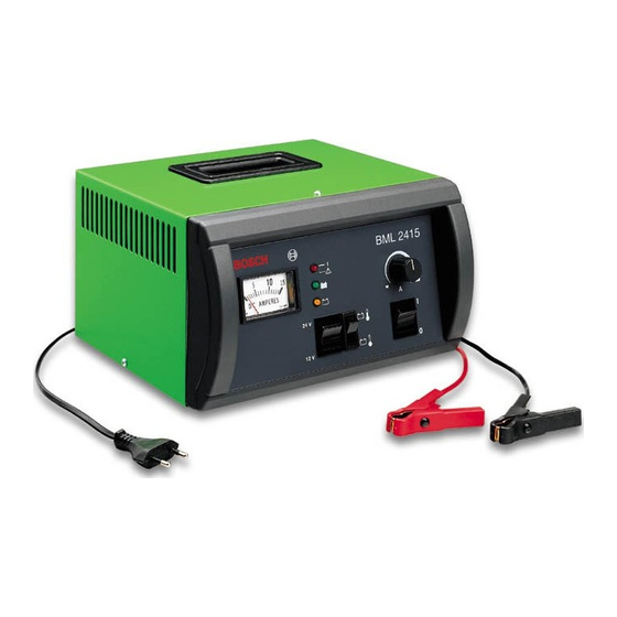
- Page 1 Instandsetzunganweisung Repair Instructions BML 2410 / BML 2410 FW / BML 2415 / BML 2415 FW Batterie Ladegeräte für 12 V / 24 V Batterien Battery chargers for 12 V / 24 V batteries...
-
Page 2: Table Of Contents
Testing the Current Consumption at No-Load Testing the Charging Current Testing the Reverse Battery Protection Testing the Secondary Voltage (12V/24V) Verdrahtungsplan / Circuit Diagram BML 2410 / BML 2410 FW BML 2415 / BML 2415 FW Explosionszeichnung / Exploded View 9 Änderungen... -
Page 3: Wichtige Hinweise
- Vielfachmessgerät z.B. Bosch Digital MMD 302 (0 684 500 302) oder handelsüblich. ! Um eine Beschädigung des Trenntransformators oder des - Volt-Ampere-Tester ETT 011.00 von Bosch (0 684 101 100) oder variabler Messwiderstand (Belastbarkeit: 500...2000W) Messgerätes zu vermeiden, stellen Sie die Ausgangsspan- und Amperemeter (Messbereich 0...200A). -
Page 4: Ladestrom Prüfen
- Belasten Sie die Batterie bis die Spannung 10...11V beträgt. Am Ladegerät muss ein Ladestrom angezeigt werden. - Erhöhen Sie den Ladestrom bis zum Maximum. beim BML 2410 beträgt der max. Strom 10A beim BML 2415 beträgt der max. Strom 15A Der maximale Ladestrom muss angezeigt werden. -
Page 5: Important Information
Part 1 or in accordance with the applicable safety regulations of the particular country. Test Apparatus and Tools - Multimeter e.g. Bosch Digital MMD 302 (0 684 500 302) or another commercially available multimeter. - Volt-ampere tester ETT 011.00 manufactured by Bosch... -
Page 6: Testing The Charging Current
- Load the battery until the voltage is 10 … 11 V. The charger must display a charging current. - Increase the charging current to maximum. With BML 2410 the maximum current is 10A. With BML 2415 the maximum current is 15A. The maximum charging current must be displayed. -
Page 7: Verdrahtungsplan / Circuit Diagram
Verdrahtungsplan / Circuit Diagram BML 2410 / BML 2410 FW T1/3 T1/6 3,15AT T1/15 T1/18 T1/10 T1/14 T1/12 T1/16 4510008-1Lt... -
Page 8: Bml 2415 / Bml 2415 Fw
BML 2415 / 2415FW T1/3 T1/6 3,15AT T1/15 T1/18 T1/10 T1/14 T1/12 T1/16 4510008-1Pal Anschlusshinweis für Ampermeter V1 (1 687 235 294) / Terminal diagramm for ammeter V1 (1 687 235 294) Vorderseite / Frontside Rückseite / Backside COKA CK-550 JUMBOSOLENOID JB-550 oder... -
Page 9: Explosionszeichnung / Exploded View
Explosionszeichnung / Exploded View... -
Page 11: Änderungen
Änderungen 28.01.2004 Pal 1.Doku mit BML 2415FW erweiter 2.Kapitel 2.1 Leerlaufstrom für BML 2415FW hinzugefügt. 3.Kapitel 2.4 Sekundärsapnnung für BML 2415FW hinzugefügt 4.Kapitel 3.2 Verdrahtungsplan angepasst und Anschlusshin- weis für Ampermeter V1 (Jumbosolenoid) erweitert. 11.07.2003 Pal 1.Kapitel 3.2 neu hinzugefügt. Mit Anschlusshinweis des Amper- meters V1. - Page 12 BML 2410 0 687 000 007 BML 2415 0 687 000 008 BML 2410FW 0 687 000 009 BML 2415FW 0 687 000 010 Robert Bosch GmbH Geschäftsbereich KH Produktbereich Prüftechnik Postfach 1129 D 73201 Plochingen www.bosch.de/prueftechnik e-Mail: Bosch.Prueftechnik@de.bosch.com...
Need help?
Do you have a question about the BML 2410 and is the answer not in the manual?
Questions and answers