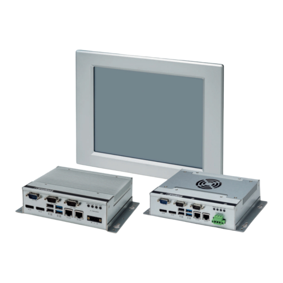
Phoenix Contact Basicline 2 Series User Manual

Phoenix Contact Basicline 2 Series User Manual

Configurable industrial pcs
Hide thumbs Also See for Basicline 2 Series:

Advertisement

Basicline 2 configurable industrial PCs
User manual
UM EN BL2 1000/2000/7000

Advertisement

Table of Contents
loading
Need help?

Need help?

Do you have a question about the Basicline 2 Series and is the answer not in the manual?

Questions and answers

Subscribe to Our Youtube Channel

Summary of Contents for Phoenix Contact Basicline 2 Series

  • Page 1 Basicline 2 configurable industrial PCs User manual UM EN BL2 1000/2000/7000...
  • Page 2 Order No. BL2 BPC 1000 2404777 BL2 PPC 1000 2404845 BL2 BPC 2000 2404844 BL2 PPC 2000 2404846 BL2 BPC 7000 1016240 BL2 PPC 7000 1016236 PHOENIX CONTACT GmbH & Co. KG • Flachsmarktstraße 8 • 32825 Blomberg • Germany phoenixcontact.com...
  • Page 3: Table Of Contents

    Service panel.......................17 5.1.1 Service panel (BL2 BPC ...) ..............17 5.1.2 Service panel (BL2 PPC ...) ..............18 Real-time clock battery ..................18 5.2.1 Battery disposal ..................20 CMOS/UEFI reset....................20 Mass storage .......................21 UEFI ........................22 Technical appendix........................23 Technical data ....................23 1/36 3799_en_D PHOENIX CONTACT...
  • Page 4 BL2 ...1000/2000/7000 Appendixes..........................29 List of figures ...................... 29 List of tables ....................... 31 Index........................33 2/36 PHOENIX CONTACT 3799_en_D...
  • Page 5: For Your Safety

    Any modifications to the systems can influence the EMC behavior. The device contains valuable recyclable materials, which should be utilized. The electronic circuit board is fitted with a lithium battery. Dispose of the device separately from other waste, i.e., via an appropriate collection site. 3/36 3799_en_D PHOENIX CONTACT...
  • Page 6: Product Changes

    Changes or modifications to hardware and software of the device are not permitted. Incorrect operation or modifications to the device can endanger your safety or damage the device. Do not repair the device yourself. If the device is defective, please contact Phoenix Contact. 4/36 PHOENIX CONTACT...
  • Page 7: Overview And Ordering Data

    DP to DVI ADPTR 2400174 Cable, DisplayPort to DisplayPort, 2 m VL 2.0M DP CABLE 2404774 Visit phoenixcontact.net/products for available accessories Replacement parts Description Type Order No. Pcs./Pkt. Connector, printed circuit board connector MSTB 2,5/ 3-STF-5,08 1777992 5/36 3799_en_D PHOENIX CONTACT...
  • Page 8 BL2 ...1000/2000/7000 6/36 PHOENIX CONTACT 3799_en_D...
  • Page 9: Installation

    Exceeding the system temperature limits can result in performance degradation of any or all components. It is therefore important that the ambient temperature of the installation environment is kept within the system temperature limits of your BL2 ...1000/2000/7000. 7/36 3799_en_D PHOENIX CONTACT...
  • Page 10: Wall Mount (Bl2 Bpc

    BL2 BPC ... to the wall. Ensure that the attaching hardware is in the small section of the keyholes. Removal Remove power and disconnect cables to the IPC. Loosen and remove the screws securing the IPC to the mounting surface. 8/36 PHOENIX CONTACT 3799_en_D...
  • Page 11: Din Rail Mount (Bl2 Bpc

    Rotate the BL2 BPC ... down against the lower edge of the DIN rail. Press in until the latch snaps closed. Secure the device on the rail with clamps. If necessary to remove, use a screwdriver to release the latch and rotate the device away from the rail. 9/36 3799_en_D PHOENIX CONTACT...
  • Page 12: Panel Mount (Bl2 Ppc

    Thread a screw (4) into every clamp. Tighten the screw on each clamp, alternating from one side to the other until the front bezel is secure against the mounting panel. Torque the screws to 0.88 Nm. 10/36 PHOENIX CONTACT 3799_en_D...
  • Page 13: Interfaces

    External display External displays can be connected to the DP ports of the BL2 ...1000/2000/7000. The BL2 BPC ... supports up to three external displays and the BL2 PPC ... supports up to two external displays. 11/36 3799_en_D PHOENIX CONTACT...
  • Page 14: Power Connection

    This device is protection class I item of equipment. UEFI is set to boot on power, allowing the system to boot as soon as the power plug is installed. This can be changed in the UEFI. 12/36 PHOENIX CONTACT 3799_en_D...
  • Page 15: Serial Communication

    The function of the pins in the D-SUB 9 connector varies with the different configuration settings. Table 3-4 D-SUB 9 pinout D-SUB 9 pin RS-232 RS-422 RS-485 TXD- TXD-/RXD- TXD+ TXD+/RXD+ RXD+ – RXD- – – – – – – – Ring indicator – – 13/36 3799_en_D PHOENIX CONTACT...
  • Page 16: Antenna

    The antenna or antenna threads onto the BL2 ...1000/2000/7000. For external antenna mounting, route and secure the antenna cable appropriately within the enclosure. NOTE: Do not allow metal chips to fall within the enclosure when creating the hole for mounting the antenna. 14/36 PHOENIX CONTACT 3799_en_D...
  • Page 17: Operation

    When 24 V DC is applied and the power switch is turned on SATA Flashes green Indicates data storage (HDD or SSD) activity Reserved for future use ERROR Orange Indicates processor is actively thermal throttling Indicates processor has shut down due to overheating 15/36 3799_en_D PHOENIX CONTACT...
  • Page 18 BL2 ...1000/2000/7000 16/36 PHOENIX CONTACT 3799_en_D...
  • Page 19: Maintenance

    Place the unit on a flat surface with the heat sink down. Figure 5-1 Component access via service panel Loosen and remove the four screws (1) that hold the service panel (2) to the case and remove the panel. 17/36 3799_en_D PHOENIX CONTACT...
  • Page 20: Service Panel (Bl2 Ppc

    Store the photos or documents on a different device so they are accessible in the event of a boot failure. The battery is type BR2032. The battery has a typical life of five years and may require replacement. 18/36 PHOENIX CONTACT 3799_en_D...
  • Page 21 CMOS and UEFI settings have been reset to the factory defaults. During the boot process, press the <F2> key to access the UEFI settings (see “UEFI” on page 22). Update the UEFI configuration with any appropriate user-defined requirements. 19/36 3799_en_D PHOENIX CONTACT...
  • Page 22: Battery Disposal

    The CMOS and UEFI reset buttons are intended to be used only by advanced users or if directed to do so by Phoenix Contact technical service. After the reset, the UEFI will need to be reconfigured to account for any user-defined settings.
  • Page 23: Mass Storage

    Remove the two screws (8) across the top of the heat sink and remove the heat sink. Thermal pads between the board and heat sink may cause resistance when removing the service panel. Locate the M.2 SSD (9) on the board. Remove the screw (10) that secures the drive in the socket. 21/36 3799_en_D PHOENIX CONTACT...
  • Page 24: Uefi

    USB drive. Press the <F12> key during the boot process to access the quick-boot menu. Highlight the device from which to boot. Press the <Enter> key to initiate the boot process. 22/36 PHOENIX CONTACT 3799_en_D...
  • Page 25: A Technical Appendix

    Power supply, nominal 24 V DC ±20% Type of connection Removable COMBICON screw-type Conductor size 0.2 … 2.5 mm² (24 … 12 AWG) Torque, wire clamping screw 0.5 … 0.6 Nm RTC battery, typical life BR2032, 5 years 23/36 3799_en_D PHOENIX CONTACT...
  • Page 26 Clock speed 1.10 GHz 1.10 GHz 2.10 GHz 2.40 GHz burst 2.50 GHz 2.90 GHz Cache 2 MB 2 MB 6 MB Number of cores Number of threads Maximum TDP 25 W Number of memory channels 24/36 PHOENIX CONTACT 3799_en_D...
  • Page 27 14.0 dBm (Channel 2-10, 54 Mbps) 11.5 dBm (Channel 11) 5 GHz (a) 12.5 dBm (Channel 36-165, 6-48 Mbps) 12.0 dBm (Channel 36-165, 54 Mbps) Current consumption, TX, typical 2.4 GHz 310 ... 580 mA 5 GHz 380 ... 790 mA 25/36 3799_en_D PHOENIX CONTACT...
  • Page 28 424.0 x 329.5 mm Outside bezel dimensions (width x height x depth) 452 x 357 x 86 mm Mechanical tests Shock test according to IEC 60068-2-27 15g with 11 ms impulse Vibration resistance according to EN 60068-2-6 26/36 PHOENIX CONTACT 3799_en_D...
  • Page 29 EN 61000-4-5:1995+ A1:2001 (Surge immunity) EN 61000-4-6:1996+ A1:2001 (Conducted radio-frequency interference) EN 61000-4-8:1993/A1:2001 (Magnetic immunity) EN 61000-4-11:2004 (Voltage dips, short interruptions, and voltage immunity tests Approvals CE compliant FCC Part 15 Class A UL/cUL UL 61010 27/36 3799_en_D PHOENIX CONTACT...
  • Page 30 BL2 ...1000/2000/7000 28/36 PHOENIX CONTACT 3799_en_D...
  • Page 31 Antenna installation ................14 Section 5 Figure 5-1: Component access via service panel ..........17 Figure 5-2: Component access via display panel removal ........18 Figure 5-3: Battery replacement ................19 Figure 5-4: CMOS jumpers ...................20 Figure 5-5: Drive replacement ................21 29/36 3799_en_D PHOENIX CONTACT...
  • Page 32 BL2 ...1000/2000/7000 30/36 PHOENIX CONTACT 3799_en_D...
  • Page 33 List of tables List of tables Section 3 Table 3-1: Display cutout dimensions ..............10 Table 3-2: Power connector..................12 Table 3-3: RS-232/422/485 communication settings ..........13 Table 3-4: D-SUB 9 pinout..................13 Section 4 Table 4-1: LED indications..................15 31/36 3799_en_D PHOENIX CONTACT...
  • Page 34 BL2 ...1000/2000/7000 32/36 PHOENIX CONTACT 3799_en_D...
  • Page 35 Display cutout dimensions ...........10 D-SUB 9 pinout ............13 External display............11 Hard drive ..............21 Interfaces ..............11 LEDs ................15 Mass storage ...............21 Mounting ................7 Panel mount (BL2 PPC ...) ...........10 Ports................11 Power................12 Safety................3 Serial communication...........13 Status LED ..............15 33/36 3799_en_D PHOENIX CONTACT...
  • Page 36 BL2 ...1000/2000/7000 34/36 PHOENIX CONTACT 3799_en_D...
  • Page 37 The receipt of technical documentation (in particular user documentation) does not constitute any further duty on the part of Phoenix Contact to furnish information on modifications to products and/or technical documentation. You are responsible to verify the suitability and intended use of the products in your specific application, in particular with regard to observing the applicable standards and regulations.
  • Page 38 Middletown, PA 17057 Should you have any suggestions or recommendations for improvement of the contents and layout of our manuals, please send your comments to: tecdoc@phoenixcontact.com 36/36 PHOENIX CONTACT GmbH & Co. KG • Flachsmarktstraße 8 • 32825 Blomberg • Germany phoenixcontact.com...

Table of Contents