Table of Contents
Advertisement
Quick Links
Model
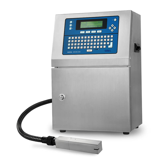
Continuous Ink Jet Printer for Industrial Use
Instruction Manual
Basic
Thank you very much for purchasing this product.
Please make sure to read this manual thoroughly for correct operation.
Further, please store this manual in a location with easy access.This manual will be
of use if you are unsure of how to operate the machine, or if a malfunction should
occur.
Advertisement
Table of Contents

Related Manuals for KGK KGKJET CCS-R


Summary of Contents for KGK KGKJET CCS-R
- Page 1 Model Continuous Ink Jet Printer for Industrial Use Instruction Manual Basic Thank you very much for purchasing this product. Please make sure to read this manual thoroughly for correct operation. Further, please store this manual in a location with easy access.This manual will be of use if you are unsure of how to operate the machine, or if a malfunction should occur.
-
Page 2: Introduction
Introduction The KGKJET CCS-R continuous ink jet printer for industrial use is designed to enable a broad range of I n t r o d u c t i o n uses as a high-speed marking machine on various production lines. -
Page 3: Safety Precautions
Safety Precautions Read the "Safety Precautions" thoroughly before use of this appliance and handle it correctly to achieve the best performance. This manual describes safety guidelines as follows to prevent bodily injury and property damage from occurring. Explanation of Symbols Disregarding this mark when handling may cause fatal or serious bodily Danger injury. - Page 4 Introduction Danger Place near source of fire There is a danger of fire. Use of fire within 10m around the appliance is Prohibition strictly prohibited. Installation in places at high temperatures is prohibited. Do not install the appliance in places subject to direct sunlight or high Prohibition temperatures for use.
-
Page 5: Power Supply
Caution Place with much electromagnetic noise from other peripheral equipment. Prohibition Welding works are strictly prohibited within 10 m around the machine. There is a possibility of malfunction. Isolate the photoelectric sensor If the photoelectric sensor is made of metal case, use the plastic mounting parts to edict 指... -
Page 6: In Case Of Emergency
Introduction Connecting Turn OFF all appliances including an external connection sequencer, PC, etc. Unplug the device from the outlet. Connect the cable to the machine. Plug in each appliance. Turn ON the power switches of each appliance. Removal ... -
Page 7: Precautions For Handling
Precautions for Handling Danger Use a container made of conductive material and connect it to ground, if, during test print or maintenance, print drops are collected in the container. edict 指 示 Print drops are electrically charged in a very small amount. If print drops accumulate, without connecting the container to ground, the amount of electric charge can become so big to cause fire. -
Page 8: Reading This Manual
Introduction Reading this Manual I t e m E x p l a n a t i o n Chapter heading ① Headline ② Sub-headline ③ Bullet point ④ Operations and Explains how to call function settings screens and the ⑤... -
Page 10: Table Of Contents
C o n t e n t s Introduction Safety Precautions ________________________________2 Explanation of Symbols__________________________2 Information Pertaining to Particular Dangers for Man _2 Installation Sites ________________________________2 Power Supply __________________________________4 Inspections ____________________________________4 In Case of Emergency ___________________________5 Precautions for Handling_________________________6 Reading this Manual _______________________________7 Main Characteristics Preparations before Use Checking Package Contents _______________________19... - Page 11 Settings ________________________________________32 Setting the Printing of Number ___________________32 Setting the Print Conditions _____________________32 Setting the Print Data ___________________________34 Creating Print Data _______________________________38 Creation Flow _________________________________38 Selecting Message Numbers_____________________39 Setting the Layout Conditions ___________________39 Registering Fixed Characters ____________________40 Changing Character Properties __________________44 Registering Blanks (blank data) at User-set Distances44 Entering Characters Not on the Control Panel ______45 Registering Numbering Characters _______________49...
- Page 12 C o n t e n t s Numbering Module _______________________________68 Numbering Character Replacement _______________68 Changing the Current Numbering Value ___________68 Barcode Module _________________________________69 Printable Barcode______________________________69 Setting Items of Each Code ______________________72 Characters Registerable ________________________73 About Code 128 _______________________________75 Barcode Module Details setting __________________75 Barcode Setting _______________________________77 Interval Module __________________________________78 User Fonts ______________________________________78...
- Page 13 Explanation of Display Screens91 Screen Configuration Table ________________________91 Screens Explanation______________________________93 Main Menu ____________________________________93 Unit Information _______________________________94 Unit Information [Detail] (Unit Test) _______________96 Editing _______________________________________97 Select Message________________________________98 Print Condition ________________________________99 Counter Value ________________________________101 Repeat Print Condition_________________________102 Edit Module __________________________________103 Calendar Module Editing _______________________105 Calendar Offset Editing ________________________105 Numbering Module Editing _____________________106 Barcode Module Editing _______________________107...
- Page 14 C o n t e n t s Operation Config _____________________________129 Level Config _________________________________130 Change Password ____________________________131 No. Date Renewal _____________________________132 Replace-character Selection ____________________132 Replace-character Edition (1) ___________________133 Replace-character Edition (2) ___________________133 Barcode Config_______________________________134 Service______________________________________135 System Status________________________________136 Work Log ____________________________________136 History Code Reference________________________137 Unit Log _____________________________________137 Measurement Log_____________________________138...
- Page 15 Maintenance ___________________________________155 Screens Used in Maintenance Work ________________156 Displaying the Screens ________________________156 Unit Information Screen________________________158 Unit Test Screen ______________________________160 Print Head Maintenance __________________________161 Mounting and Removing the Head Cover _________161 Fixing the Electrode Unit _______________________162 Cleaning the Electrode Unit_____________________163 Cleaning the Gutter and the Ink Outlet ____________166 Cleaning the Nozzle ___________________________169 Adjusting the Ink Flow Direction_________________172 Adjusting the Fully-closed Nozzle Sealing ________175...
- Page 16 C o n t e n t s Troubleshooting Q&A __________________________________________213 Printing Trouble ______________________________213 Print Head Trouble ____________________________215 Main Unit Trouble _____________________________218 Display Panel Trouble _________________________219 Error Codes and History Codes____________________221 Code Tables _________________________________221 History Code Details __________________________223 Error Code Details ____________________________223 Warning Code Details _________________________227 Alarm Code Details____________________________230 Guarantee _____________________________________237...
-
Page 18: Main Characteristics
M a i n C h a r a c t e r i s t i c s The KGKJET CCS-R (hereinafter called the "CCS-R") is a continuous ink jet printer for industrial use that can print high-quality 26-dot characters. - Page 19 Circulating ink automatically during operation stop The machine has the interval mechanism to circulate the ink automatically during operation stop. Therefore there is no worry about nozzle clogging caused by ink dry during long holidays. The time to start and end the interval mechanism can be set arbitrarily using a timer. Nozzle Gutter tube Nozzle sealed with the gutter...
-
Page 20: Preparations Before Use
Preparations before Use Checking Package Contents P r e p a r a t i o n s b e f o r e U s e One set of CCS-R includes the following: CCS-R Main Unit Instruction Manual Model Continuous Ink Jet Printer for Industrial Use Instruction Manual Basic... - Page 21 Dryer Electrode fixing jig Tweezers Stirrer Magnifier (pigment ink machine only) Spare parts of replacement Diaphragm unit or Diaphragm set (pigment ink only) Diaphragm unit Diaphragm set Product Name Remarks Quantity CCS-R Main Unit Instruction Manual Maintenance Set Washing bottle Used with cleaning liquid.
- Page 22 Preparations before Use Product Name Remarks Quantity Replacement parts for the circulation Spare parts of Diaphragm unit or pump. Diaphragm set replacement (pigment ink only) The following tools are not included in this maintenance set, but are very useful to have. Product Name Remarks Hexagon nut spinner (5.5mm)
-
Page 23: Product Configuration
Product Configuration Basic Configuration The standard product configuration comprises the CCS-R main unit, print head, and head cable. I t e m E x p l a n a t i o n Print head Prints characters onto the current print target (i.e., the product to be printed). -
Page 24: Optional Configurations
Preparations before Use Optional Configurations P r o d u c t N a m e R e m a r k s Photoelectric sensor Diffused reflection type and transmission type of photoelectric sensors are available. The available mounting methods are conveyer mounting and head mounting types. Rotary encoder set Enables printing at constant pitch on the conveyer even with fluctuating speeds. -
Page 26: Part Names
Part Names CCS-R Main Unit P a r t N a m e s Appearance I t e m E x p l a n a t i o n Control Panel Displays information on the LCD, and enables items to be selected and characters to be entered using the keyboard. -
Page 27: Interior
Interior Pigment ink unit Standard unit p p p p p p p I t e m E x p l a n a t i o n Valve Unit Controls the flow of ink. Regulator Controls the ink pressure. Pressure Sensor Measures the ink pressure. -
Page 28: Control Panel
Part Names Control Panel I t e m E x p l a n a t i o n Flashes during warmup, and then is lit green when printing is Operation Lamp enabled. Supply Lamp Lit orange when either the remaining ink or solvent is low. Warning Lamp Lit red if a malfunction occurs. -
Page 29: Print Head
Print Head Interior Appearance I t e m E x p l a n a t i o n Print Head Print Head Cover Filters impurities from the ink circulating through the print Ink Filter Case head. Piezo Heater Warms the ink if environmental temperature is low. Electrode Fixing Jig The hole for inserting the electrode fixing jig. -
Page 30: Basic Use
Basic Use Operation Flow B a s i c U s e Turn on power Operate the head Create print detail ・ Set print number Settings ・ Set print condition ・ Set print data Print Stop the head Turn off power Turn ON the Power Supply Press and hold the "Power" key in the top right of the control panel for approx. -
Page 31: Operating The Head
Operating the Head Press the (Drive) key in the "Main Menu". The icon that displays the head status will change from STOP to RUN, and the display will change (from Drive to Stop). The operations LED on the top left of the control panel will start to flash. -
Page 32: Turning Off The Power Supply
Basic Use Turning OFF the Power Supply Press the key in the "Main Menu" to change the function key allocations. Press the (Quit) key. A check message will be displayed, so press key, select " YES", and then press ... -
Page 33: Settings
Settings Setting the Printing of Number Press the (Edit) key in the "Main Menu". The edit functions will be displayed. Press the keys and select "Select Message", and then press the key. message selection screen will ... - Page 34 Basic Use Edit the print conditions for the required items. Press the keys to select the item to be edited. Press the keys or the key to change the values and selected items. Reference Select the value input type for the edit items ...
-
Page 35: Setting The Print Data
Edit Items Explanation Settings Range Prt. Direction Sets whether to print the printing information from the Forward / Back start (forwards) or from the end (back). Prt. Reflects the top and bottom orientation of the characters. Normal / Down Orientation OFF Filter Set to prevent misoperation due to print command 0.0 to 13107.1 [mm]... - Page 36 Basic Use When the message editing screen has been displayed, move the cursor to the module to be changed (in units of print data), and select the module (enclosed in the dotted lines). Once selected, press the key. Left to right ・...
- Page 37 Edits the module details. Left to right ・ Cursor position ・ Max capacity in number of characters Remain capacity in ・ Current delete mode number of characters Cursor ・ Current input mode Module content Explanation Moves the cursor. Back space (Deletes the character immediately before the cursor.) Alternatively, deletes the character at the cursor position. Turns ON and OFF the Caps Lock.
- Page 38 Basic Use Press the keys to move the cursor to immediately before (i.e., to the right of) the character to be deleted. Press the key to delete the unnecessary character. Enter the new characters. Reference If entering characters that are not on the ...
-
Page 39: Creating Print Data
Creating Print Data Creation Flow Print data are created using the following flow. Select message number layout condition Register Register Register blanks at Register Set new Register date characters numbering characters user-set distance barcode layout condition fixed characters barcode details Change character properties Save message number This section explains how to register the following data as an example. Message No.: 02 Print data: Number of scan dots : 16... -
Page 40: Selecting Message Numbers
Basic Use Selecting Message Numbers Press the (Edit) key in the "Main Menu". The edit functions will be displayed, so press keys to select "Edit Message" and then press the key. message selection screen will ... -
Page 41: Registering Fixed Characters
Number of scan dots: 20 dots, No. of print lines: In the case of one line. Vertical : 20 dots Allocated on the downside 1st line Number of scan dots: 20 dots, No. of print lines: In the case of two lines. 10 dots 1st line Vertical : 20 dots 10 dots 2nd line Registering Fixed Characters... - Page 42 Basic Use Explanation Inserts a new numbering module (printing of number). Inserts a new barcode module (printing of barcode). Inserts interval module (printing of space). Creates a new layout. Edits existing data (modules and layouts). ...
- Page 43 This completes the "NET.1Kg" entry. Character Entry Screen Left to right ・ Cursor position ・ Max capacity in number of characters ・ Current delete mode Cursor ・ Current input mode Module content Remain capacity in number of characters Explanation Moves the cursor. Back space (Deletes the character immediately before the cursor.) Alternatively, deletes the character at the cursor position. Turns ON and OFF the Caps Lock.
- Page 44 Basic Use Explanation Terminates the inputs. (End) Switches the display between the function key above and the function key below. Switches processing (delete mode) when the has been pressed. (DEL/BS) The current delete mode is displayed in the top right of the screen. ...
-
Page 45: Changing Character Properties
Changing Character Properties The font size (character size) and character spacing (distance between characters), etc., of characters that have already been entered can be changed. Use the cursor to select the details to be changed, and then press the key. -
Page 46: Entering Characters Not On The Control Panel
Basic Use The blank (interval module) edit screen will be displayed. Edit the distances (intervals), and then press the key. In this example, 45.0 has been entered. A check message will be displayed, so press key, select "Yes"... - Page 47 Enter the "LOT Nr" by pressing the character keys on the control panel. The character key corresponding to the "…" is not on the control panel, so press the (Select) key to select the character. The characters that can be selected are displayed in the center left of the screen, so ...
- Page 48 Basic Use Character Entry Screen Selected types of characters are displayed. Screen scrolling is available to select excess characters. Caracter type Cursor Explanation Moves the cursor. Functions in the character code input mode. [A] to [F] Enters a character code. Returns to the previous screen. Enters the character selected using the cursor. ...
- Page 49 During editing Text module or Calendar module if you press the key, the selectable character type will be changed as follows. ※Only when editing calendar module. In editing Barcode module, special signs for barcode will be displayed as follows. (Selectable characters change depending on Barcode type)
-
Page 50: Registering Numbering Characters
Basic Use Registering Numbering Characters Register new numbering characters. Firstly, move the cursor to the registration start position. In this example, move the cursor to the (150,0) position. Next, press the key. The numbering character selection screen will be displayed. -
Page 51: Registering Date Characters
The numbering character has been registered to the message. Refer to "Changing Character Properties" to edit the conditions as described below. Font size: 9 × 7 Char.Direction: ↑ (Unchanged) Multiple: 1 (Unchanged) Char.Space: 1 Registering Date Characters ... - Page 52 Basic Use Entry of the character details has been completed, but if left as is, the current time will be printed, so enter the difference between the current time and the expiration date. Press the (Offset) key. The offset amount edit screen will be displayed.
-
Page 53: Registering Barcode
Registering Barcode Register new barcodes. First of all, change back layout of Calendar characters to the one for one line. Press the key. Referring to “Setting the Layout Conditions”, edit conditions as follows. Vertical: 26 dots ... - Page 54 Basic Use When the editing is over, press the (Category) key. As the setting items for OCR will be shown, edit conditions as follows. Append OCR: OK Space: 1 Omit CD: OK Divide: Cancel Reference To change classification for setting items, ...
-
Page 55: Saving Message Numbers
Saving Message Numbers Once the print data have been edited as desired, press the key in the message edit screen. A check message will be displayed, so press key, select " Y es" , and then press the key. -
Page 56: Advanced Use
Advanced Use Character / Printing Calibration A d v a n c e d U s e Characters Used The following characters can be used. Use country Characters JAPAN Alphabet, numeral, symbols, hiragana, katakana, kanji (JIS No.1 and No.2 CHINA standards), simplified Chinese characters (GB2312), and user-defined characters (192 characters max.) Other... -
Page 57: Print Speed
Print Speed By setting the conveyer speed beforehand, the details of the items set by the distance such as print position and horizontal dot pitch, etc., are correctly expressed in the print results. Print speed can be set for each message in the range 1.0 to 350.0m per minute. In reality, however, the settable range depends on the number of scan dots, the horizontal dot pitch, and the interspacing. -
Page 58: Filter
Advanced Use Filter Print commands use photoelectric sensors or external signals. If chattering occurs in these signals, trouble such as failure to print, print position error, or skipping numbering, etc., may occur. This occurs due to the chattering timing and a characteristic that ignores print commands entered during CCS-R print operations (print position standby and printing after the print command has been entered). - Page 59 If the space between jobs is too great: skipping numbering Chattering Narrowew interval Print command Print position standby In progress Printing Stop Numbering skipping Ready Ready to receive print command Busy Printed outside the print target due to chattering CCS-R is equipped with a "filter" function to prevent this type of trouble. The "filter" functions to remove exceptional print commands by performing compensation within the CCS-R even if chattering occurs in the photoelectric sensors (or external signals).
- Page 60 Advanced Use ON filter operation Internal compensation method: Aims to prevent the troubles described above by rechecking after the print command has been turned ON and the set distance has been traveled. If the signal is ON, printing is performed, and if the signal is OFF, the print command is ignored. Caution ...
-
Page 61: Repeat Printing
Repeat Printing This function repeatedly prints the same content to the number of times specified. The following two types of print conditions can be selected. Trigger: Prints repeatedly the specified number of times after the print command has been turned The number of times can be set from 1 to 9999. -
Page 62: Calendar Module
Advanced Use Calendar Module This function performs printing while automatically updating the production date and expiration date (i.e., best before), etc. 10 calendar modules can be registered. The expiration (best before) date is defined using offsets against the production date (for example, one month from the production date), and the expiration date offset can be set in units of years, months, days, hours, and minutes. - Page 63 MA: Month 1-Digit Expression Prints the months January to December by replacing with 1-digit characters. The default settings are described below. Month Replacement TA: Hour 1-digit Expression Prints the hours from 0 to 23 in the 24-hour clock by replacing with 1-digit characters. The default settings are described below.
- Page 64 Advanced Use MP: AM and PM Characters AM and PM characters express morning and afternoon, and print the one character replaced after being calculated based on the amount of calendar offset. The default for the changeover time between AM and PM is 12:00, but this can be changed using the calendar settings.
-
Page 65: Start Of Week Number Setting
WN: Week Number The week number is the number replaced in weekly units, taking 1 January to be Week 1. The week number is expressed using two digits, and the topmost digit is filled in using 0. (Zero suppression is disabled.) The week number is calculated based on the amount of calendar offset, and when the year changes the week is reset (i.e., 1 January becomes Week 1 again). - Page 66 Advanced Use DT: Beginning, Middle, and End of the Month Prints a single character dividing one month into the beginning, middle, and end. The default settings are described below. Period Replacement 1 to 10 of the month Beginning 11 to 20 of the month Middle 21st of the month to the end DC: Day 1-digit Expression...
-
Page 67: Calendar Character Replacement
mA: Minute 1-Digit Expression Prints the minutes within an hour by replacing with 1-digit characters. The default settings are described below. Minute Replacement Minute Replacement Minute Replacement Minute Replacement SC: Shift code One day is divided into max 10 work shift, and can print some characters (1 to 10) for each work shift. The example of printing are described below. -
Page 68: Day Of The Week Setting
Advanced Use Day of the Week Setting This function sets which day of the week to use as the start of the week. The function is referenced when printing the number of weeks elapsed since the start of the year using the week number character, which is one of the calendar characters. -
Page 69: Numbering Module
Start of week number setting This function sets the first week of week number. The function is referenced when printing using a single calendar character for week number. Settings Operation January 1 The first week of a year starts with January 1st. Week of 1st Sun The first week of a year is a seven-day period that contains the first given ~ Week of 1st Sat... -
Page 70: Barcode Module
Advanced Use Barcode Module Print the bar pattern to correspond to the registered data (numericals and signs) . You can register upto ten barcode modules. You can freely set the size of the bar element. As it is assumed that the barcode printed will be read by a reading device, printing quality is extremely important. - Page 71 Risk rate for Print quality incorrect Type Character type Bar type requirement readability 2 steps Numericals Normal High x 2 colors Code39 Alphanumericals and signs. ( -.$/+% ) 2 steps Normal High x 2 colors NW-7 2 steps Numericals and signs. ( -.$/+ ) Normal Normal x 2 colors...
- Page 72 Advanced Use Bar density The bar density of the barcode can be set by the horizontal dot pitch setting for printing conditions. ( Refer to" P32: Setting the print conditions". ) Horizontal dot pitch Ink blurring after printing Bar density A gap formed between bars may When being less dense, MRD Bar width consistent, thus good cause failure.
-
Page 73: Setting Items Of Each Code
Setting Items of Each Code It is required to make settings as below in addition to data for encoding of barcode. ( Refer to" P107: Barcode Module Details". ) Type Image Items to be set Bar height Bearer bar (Top) (Right) ... -
Page 74: Characters Registerable
Advanced Use Characters Registerable Characters registerable for each barcode type are as below. You can create a barcode pattern by registering these number of characters and module in the barcode module. Type Number of data variable character Check digit (CD) 2 to 32 (even number) Supporting Modulus 10 / 3... - Page 75 Variable character Variable characters such as module type or number can also be registered as barcode. Variable character Image display Calendar module 〜 Numbering module 〜 Others than numbers should be ignored. In the event the digit setting barcode may not correspond to the right digit, then add zero in an automatic mode to make adjustment.
-
Page 76: About Code 128
Advanced Use About Code 128 Refer to below for Code 128 in the CCS-series. Optimization In Code 128, some codes of group A doublicate to those in the group B while the codes that will not duplicate are special codes for use for ESC sequence. This is why CCS will not employ the codes of group A. - Page 77 About division of OCR The standard regulations of ITF defines that spacing is made in OCR as below. With CCS spacing can automatically be inserted by setting so. Number Version Division position of digit 12345 6 Add on 123 45678 90123 4 Standard 12345 67890 12345 6 Extension...
-
Page 78: Barcode Setting
Advanced Use Barcode Setting In the screen for barcode setting, setting of barcode module space and bar element size will be made. There are eight bars at maximum by the combinationof black, white, thin and thick bars. To set number of dots to be used for printing each. Be sure to confirm the imaging size for all messages for which the barcode module has been registered. -
Page 79: Interval Module
Interval Module This function inserts long spaces between characters. The space cam be set in millimeters from 0.1 to 999.9mm. A maximum of 10 intervals can be registered. A blank character can be used for short spaces, but this function is effective if the space is long and the number of characters is insufficient. - Page 80 Advanced Use User Font Information Screen Displays the information about the user font User Font Explanation Information Life Displays the number of possible user font updates. Update Date Displays the date and time the details were last updated. * Not displayed immediately after shipment. Comment Edits comments. No.
-
Page 81: Editing User Fonts
User Font Selection Screen Cursor to select Displays explanation user font storage number of the user font Cursor to select Displays user font image font size Explanation Enables cursor selection and scrolling of the number under which the user font has been saved. Enables cursor selection and scrolling of the size of the user font to be edited. - Page 82 Advanced Use User Font Edit Screen Storage number and font size Edit area of user font Number of ON dot, and cursor position Functions allocated to [1]〜[H] keys Displays overall image Explanation Moves the cursor. When edit the proportional font, change the font width. Implements the allocated functions. to [H] For the allocated functions, refer to "Function Icons" below. ...
- Page 83 Dot ON (Draw) and OFF (Delete) Press the keys to move the cursor. Press the key to turn ON and OFF the dots. Press and hold the key while pressing the keys to draw a straight line. ...
- Page 84 Advanced Use " Fill" Command First move the cursor to the area to be filled, and then press the key. Press the (Dots OFF) key. To turn ON the dots press the key, and to ...
- Page 85 " : Undo" Command Press the [H] key. Returns to the pattern immediately before the last operation. " : 90deg Rotation" Command When the allocated functions have been changed, press the [Q] key. The whole pattern has been rotated 90 degrees.
-
Page 86: Entering Explanatory Text
Advanced Use Entering Explanatory Text Editing the font pattern has been completed, but the explanatory text is "unregistered", so printing cannot yet be performed. Press the (Explanation) key to enter the explanatory text. Enter the explanatory text, and then press the ... -
Page 87: Managing Consumables
Managing Consumables A consumables management function is built into CCS-R. If set in advance, at the set time an information screen will be displayed (and a buzzer will sound), to notify that the set date has arrived. Use this function to estimate when to replace parts that must be replaced periodically. Operations Explanation This section explains the setting procedure and operations using ink management as an example. -
Page 88: Settings Procedure
Advanced Use Settings Procedure Select "Manage Consumables" in the service screen. The advanced settings screen will be displayed. Move to the advanced settings screen by selecting the items. Make the advance settings. Selectable type and settings range Type Meaning Remarks... -
Page 89: Other Functions
Other Functions Speed Tracking Printing Printing can be performed at a fixed itch even if the conveyer speed fluctuates violently by receiving speed tracking signals from a rotary encoder. Either the internal clock or a rotary encoder can be set as the print clock. The following settings are available if using a rotary encoder. -
Page 90: I/O Test
Advanced Use I/O Test This function can test operations such as monitoring external input signals, output signals, and the pumps and valves, etc. System Status Display Displays the system software, DSP software, and font versions that have been installed, and the status of the settings switches. -
Page 92: Explanation Of Display Screens91
Explanation of Display Screen Configuration Table E x p l a n a t i o n o f D i s p l a y S c r e e n s Level 0 Level 1 Level 2 Level 3 Level 4 Unit information 93 Main menu... - Page 93 Level 0 Level 1 Level 2 Level 3 Level 4 93 Main menu 135 Service 136 System Status Status History code 136 Work Log reference 137 Unit Log Measurement Exp. Exp. Management (1) Management (2) Unit Test Test 140 Forced Print 141 Bleed Process 141 Forced mixing Recirculation...
-
Page 94: Screens Explanation
Explanation of Display Screens Screens Explanation The screens are described below. Main Menu With the CCS-R main menu screen, this screen is displayed after the power supply has been turned ON, so operations can be performed. 1 2 4 3 Item Explanation Displays the number of the message to be printed. -
Page 95: Unit Information
Icons that describe unit status. Icon Explanation Head is stopped. Head is operating (or the operation is being processed). Head cover is open. Ink amount is low. Solvent amount is low. Ink viscosity is too high. Ink viscosity is too low. The ink leak out from the ink pump. - Page 96 Explanation of Display Screens Process Displays the unit test screen. (Detail) Switches to maintenance mode. (Mainte) Returns to the previous screen. In maintenance mode, the gutter, valves, pumps, and head heater, etc., can be operated individually. The display for the part being operated is highlighted. Process Turns ON and OFF the head heater.
-
Page 97: Unit Information [Detail] (Unit Test)
Unit Information [Detail] (Unit Test) Enables sensor inputs to be displayed and valves to be operated individually, etc. Input Display Output Display 1 2 Output Display--Maintenance Mode 3 Item Explanation Displays inputs from the sensors. Displays the operating status of the gutter and valves, etc. Switches to gutter and valve operating status. -
Page 98: Editing
Explanation of Display Screens Editing Displays the print settings. Item Explanation Select Message Selects the number of the message to be printed. Print Condition Edits the print conditions. Edit Message Edits the messages. Counter Value Edits the current counter value of the numbering module. Edit Module Edits the special modules. -
Page 99: Select Message
Select Message This screen selects the number of the message to be printed. Detail display 1 2 List display 1 Item Explanation Displays the cursor and the number of the message selected. The print data are registered to the number displayed as highlighted. Displays the print image for the selected message. -
Page 100: Print Condition
Explanation of Display Screens Print Condition This screen displays and edits the print conditions for the message currently being printed. Process Selects items to be edited, and scrolls the display. Increases and decreases values, and changes the selected item. ... - Page 101 Edit Items Explanation Settings Range Prt. Position Sets the distance from after the print command has been 0.0 to 13107.1 [mm] entered (photoelectric sensor) to the stast of printing. Prt. Speed By setting the conveyer speed beforehand, the details of 1.0 to 500.0 [m/min.] the items set by the distance such as print position and horizontal dot pitch, etc., are correctly reflected in the...
-
Page 102: Counter Value
Explanation of Display Screens Counter Value This screen enables the values of the currently registered numbering module to be changed. Item Explanation The numbering module number. Only registered numbers are displayed. Counter Displays the current counter value. (The edited details are not saved until the key is pressed.) Repeat Displays the current repeat value. -
Page 103: Repeat Print Condition
Repeat Print Condition This screen displays and edits the repeat-printing conditions for the message currently being printed. Process Selects items to be edited, and scrolls the display. Increases and decreases values, and changes the selected item. Enters and deletes values. -
Page 104: Edit Module
Explanation of Display Screens Edit Module Use this screen to select and edit the special module types and numbers. Calendar Module Display 1 2 Numbering Module Display 3 4 Barcode Module Display Interval Module Display Item Explanation Displays the registered details of the calendar module. (Displayed in two lines if the registered information is too long.) Displays the calendar offset amount (i.e., the difference from the system time). - Page 105 Process Selects the module number, and scrolls the display. Edits the special modules (when saving to messages). (Edit) Changes the kind of the special module displayed (when edit module). (Kind) Copies the details of the selected module number to another number. (Copy) ...
-
Page 106: Calendar Module Editing
Explanation of Display Screens Calendar Module Editing This screen edits the calendar modules. Process Edits the calendar offset amount (i.e., the difference from the system time). (Offset) Note: For details, refer to the "P61: Calendar Module". Calendar Offset Editing Sets how much to offset the calendar module print data from the system clock. -
Page 107: Numbering Module Editing
Numbering Module Editing This screen edits the numbering modules. Item Explanation Entry Range Figure Displays the number of numbering digits. 1〜8 Start Displays the initial (i.e., start) numbering value. 0〜99999999 Increment Displays the increments when counting up (or down) -9999〜+9999 the numbering. -
Page 108: Barcode Module Editing
Explanation of Display Screens Barcode Module Editing Barcode module editing screen. Process Barcode type to be shown will be changed. (CodeType) Details of barcode module will be set. (Detail) Note: For details, refer to the "P69: Barcode Module". Barcode Module Details Set the barcode module details. - Page 109 Category Item Explanation Barcode Height Set the number of the vertical dots for barcode. (Input range : 3 to 26) Valid Vertical Dot Setting is possible only for this range. Vertical Dot The height and the overall barcode height set by OCR setting will be shown.
-
Page 110: Interval Module Editing
Explanation of Display Screens Process Selects items to be edited, and scrolls the display. Increases and decreases the value. Enters and deletes values. Reclassify the items for setting. (Category) Sets the details being edited. ... -
Page 111: Edit Message (Message Selection)
Edit Message (Message Selection) This screen edits the user-defined message numbers. Detail display 1 2 Lists display 1 Item Explanation Displays the cursor and the number of the message selected. The print data are registered to the number displayed as highlighted. Displays the print image for the selected message. -
Page 112: Message Editing
Explanation of Display Screens Message Editing This screen edits messages. 1 2 4 3 5 Item Explanation Displays the number of the message being edited. Displays the cursor coordinates. From the left Number of characters using the the message being edited (text modules only). ... -
Page 113: Message Layout
Process Deletes the selected layout and module. (If the layout is deleted, the modules within the layout are also deleted.) Returns to the previous screen. Ends message editing. * Icons are not displayed for functions that cannot be operated using the cursor position. Note: For details, refer to "P40: Registering Fixed Characters". -
Page 114: Text Module Editing
Explanation of Display Screens Text Module Editing Edits and registers text modules. Character Properties Edits the module properties. Item Explanation Valid Vertical Dot Only "font sizes" and "character orientation" within this range can be set. Font size Describes the character size. (Available values: 24x24, 24x18, 16x16, 16x12, 12x10, 10x8, 9x9, 9x7, 7xN, 7x8, 7x5, 5xN, 5x5 ) Char.Direction... -
Page 115: Config
Config This screen displays the settings concerning the overall unit. Properties Item Explanation System System Clock Moves to the "System Clock" screen. Interval Running Moves to the "Interval Running" screen. Unit Config Moves to the "Unit Config" screen. CHG Detect Rectify Moves to the "CHG Detect Rectify"... -
Page 116: System Clock
Explanation of Display Screens System Clock Sets the standard clock for the CCS-R system. Item Explanation System Clock Displays the year, month, day, hour, minute, and second. The input range is described below. Year: 2000〜2099 Month: 1〜12 Day: 1 to 31 (Changes depending on the month and leap years.) Hour: 0〜23 Minute: 0〜59 Second: 0〜59... -
Page 117: Interval Running
Interval Running Sets the timer for interval operations. Further, interval operation is a function that stabilizes the ink temperature and viscosity when the power supply is turned ON and before printing starts to enable stable printing to be performed during actual use. - Page 118 Explanation of Display Screens If printing is not performed during interval operations, the power supply will turn OFF automatically while the interval operations are OFF. Turn ON power supply Turn OFF Time Interval operation Interval operation Interval operation If printing is performed (or maintenance processing is executed) during interval operations, turning OFF the interval operation will be disabled, and the power supply cannot be turned OFF automatically.
-
Page 119: Unit Config
Unit Config Sets items that have a low probability of being reset. Item Explanation One-Shot Print When printing is enable, this function performs printing once only when a print command is entered from the photoelectric sensor. (That is, printing using further print commands is not performed.) If printing again, head operations or t h e print data settings must be performed again. -
Page 120: Chg Detect Rectify
Explanation of Display Screens CHG Detect Rectify Adjusts the detection time (note: not the ink droplet) during the start of normal head operations only, but constantly monitors the detection time during operations using this function, and if the tolerances are exceeded, the detection time is compensated to enable stable printing. Item Explanation Method... - Page 121 Compensation Explanation Method Interlock Displays an alarm screen and stops printing if the detection time exceeds the tolerances. Note: "Restore" using the alarm screen: Readjusts the detection time to within the charge detection time, and resumes printing. Variable Changes the detection time set value and viscosity standard value depending on head temperature and ambient temperature changes, and adjusts the detection time and ink viscosity.
-
Page 122: Interspacing Type
Explanation of Display Screens Interspacing Type Sets whether to perform "interspacing editing" using the "Print Conditions Editing" screen either manually or automatically. Item Explanation Interspacing Type Display whether to perform "interspacing" settings manually. (Available values: Manual or automatic) Note:If the interspacing type is auto, the optimum value obtained from the "Print speed" setting is set as the "interspacing", so manual editing is disabled. -
Page 123: Encoder Config
Encoder Config Sets whether or not to use the encoder, and makes settings regarding rotary encoder operating specifications. Item Explanation Use Encoder Displays whether or not to use the rotary encoder. (Available values: YES, NO) Pulse Displays the number of output pulses per one rotary encoder rotation. (Entry Range: 100 to 10000) Distance Displays the line travel distance per one rotary encoder rotation. -
Page 124: Photo Sensor Monitoring
Explanation of Display Screens Photo Sensor Monitoring If the head is operating, sets whether the print command signals from the photoelectric sensor output an alarm if the sensor is ON for longer than a set period. (This is to prevent malfunctions such as no- printing if the object being printed upon stops in front of the photoelectric sensor, or if the photoelectric sensor is dirty, etc.) Item... -
Page 125: Transmit Config
Transmit Config Sets the communications conditions. Item Explanation Baud Rate Displays the baud rate. (Available values: 4800, 9600, 19200, 38400, 57600, and 76800) Char. Length Displays the character length. (Available values: 7 bits and 8 bits) Parity Displays the parity check. (Available values: NO, odd, even) Stop Bit Displays the stop bit. -
Page 126: I/O Output Condition
Explanation of Display Screens I/O Output Condition Sets the output conditions for the I/O output "ready signal" (i.e., printing is possible) and "printing". Item Explanation Printing disable Displays the status of switches 1 to 3 in the following diagram. Printing & Waiting Preparing for the data “Ready”... -
Page 127: Priority Management
Priority Management If any keys are operated while communications with the host device such as a PC are being processed, processing may be delayed or not performed. (If the processing interval is approx. 0.5s or greater, there is no problem.) To improve this situation, this screen sets the processing priorities. -
Page 128: Calendar Config
Explanation of Display Screens Calendar Config This screen settings related to the calendar module. (These are not reflected in the system clock.) Item Explanation Week Config Displays the start and end days of the week used to calculate the week number. -
Page 129: Shift-Code Config
Shift-code Config This screen settings related to the shift-code. 1 2 3 4 Item Explanation From the left Selected shift-code No. Number of shift-code.(Number of partitions) is displayed. Displays the start time of selected shift. Displays the selected shift, previous one and next one. Displays the printing contents of selected shift. -
Page 130: Operation Config
Explanation of Display Screens Operation Config Performs the operations settings. Item Explanation Beep Displays whether the alarm will sound, and whether the keys beep when operated. Realtime Update Displays whether to update the calendar and numbering modules in real time for print images on the "Main Menu" screen. Backlight OFF Displays how many minutes after the last key was touched that the backlight turns OFF. -
Page 131: Level Config
Level Config Sets the user interface such as display language, etc. Item Explanation Language Displays the display language. (Available selections: Japanese, Chinese, English) Operate Lv. Displays the operations level concerning editing and messages (print data). If changing to a higher operating level, a password must be entered. (Available selections: Lv0.Can’t edit, Lv1.Can edit, Lv2.Can all) Lv0.Can’t edit: Only switching of message No. -
Page 132: Change Password
Explanation of Display Screens Change Password If changing the operating level for messages (print data) and editing to a higher level, a password must be entered. The password can be changed using this screen. Select the password to be changed. ... -
Page 133: No. Date Renewal
No. Date Renewal Makes the settings concerning resets when the date is updated in the numbering module. Item Explanation Process Displays the module to be reset when the date is updated. (Available selections: Reset printing module, or reset all module.) Process ... -
Page 134: Replace-Character Edition (1)
Explanation of Display Screens Replace-character Edition (1) Selects one character to be replaced by another character for one character type. 1 2 3 Item Explanation Displays the type and explanation of character. Displays the character to be replaced. Displays the character after replacement. Process ... -
Page 135: Barcode Config
Barcode Config Set the Barcode Module blank and bar thickness. Item Explanation First space Set the width of space (quiet zone) first and last (left and right) barcode. / Last space (Input range : 1 to 300 dots) Narrower line Set width of the line (black bar). -
Page 136: Service
Explanation of Display Screens Service Displays items concerning status and maintenance, etc. of the machine Properties Item Explanation Status System Status Moves to the "System Status" screen. Work Log Moves to the "Work Log" screen. Unit Log Moves to the "Unit Log" screen. Measurement Log Moves to the "Mesurement Log"... -
Page 137: System Status
System Status This screen displays the status of the DIP switches on the PCB mounted to the unit and the versions of the system software, DSP software, and font versions installed in the CCS-R. Process Scrolls the display Displays the version of the software and data installed. -
Page 138: History Code Reference
Explanation of Display Screens History Code Reference This screen displays and explanation of the codes for the histories in the "Operations History" screen. Process Scrolls the display. Returns to the previous screen. Unit Log This screen displays the power ON time, operating time, and number of prints to date for the unit. Item Explanation Turn ON Time... -
Page 139: Measurement Log
Measurement Log Displays the history of the viscosity measurements. Item Explanation A maximum of 500 events can be stored in history. Log time Displays the measuring time. U.Temp Displays the unit temperature. Fall Displays the drop time (ink viscosity). Refil Displays the time that the viscosity measurement tank was filled with ink. -
Page 140: Exp. Management (1)
Explanation of Display Screens Exp. Management (1) Selects items for the management of consumables. Process Selects items to be edited, and scrolls the display. Edits the consumables information for the selected items. Returns to the previous screen. Note: For consumables management, refer to "P86: Consumables Management". -
Page 141: Forced Print
Process Selects the items to be edited. Sets the management method and replacement time automatically. (Auto) (The edited details are not saved until the key is pressed.) Displayed when ‘Free1’ or ‘Free2’ item selected to edit the content of the ... -
Page 142: Bleed Process
Explanation of Display Screens Bleed Process This screen expels air from the tubes. And, displays the unit operating status. Process Starts and stops the bleed processing. (Bleed) (The display during processing is hightlighted.) Returns to the previous screen. (Stop the bleed processing) Note: About the display of the unit operating status, refer to "P94: Unit Information". -
Page 143: Recirculation Process
Recirculation Process This screen normalizes fluids (i.e., removes air and dust) circulating within the pipes. And, displays the unit operating status. Screen of operating status Screen of editing condition Item Explanation Nozzle Displays the type of nozzle mounted to the ink jet. Aging : A large-caliber nozzle specifically for performing aging. -
Page 144: Draining Process
Explanation of Display Screens Draining Process Drains ink and solvent from the tanks. Selects the tank to be drained. A check message is displayed. Perform discharge according to the on- screen instructions. Process Changes the selections. ... -
Page 145: I/O Test
I/O Test This screen checks the output operations to external devices by enabling the user to turn ON and OFF the I/O connector output signals at will. Process Selects the test item. Turns ON and OFF the signal status. Switches to test mode. -
Page 146: Head Parameter
Explanation of Display Screens Head Parameter Sets the print-related head items. Item Explanation Deflect Voltage Displays the voltage output to the biased poles using digital command values. (Entry Range: 0 to 255) Charge Detect Time Displays the ink droplet adjustment value using the time from ink droplet electrification to passing through the detector electrode. -
Page 148: Inspection And Maintenance
Inspection and Maintenance To use the device in a satisfactory condition for a long time, and to maintain a satisfactory quality at I n s p e c t i o n a n d M a i n t e n a n c e all times, make sure to read thoroughly this "7. -
Page 149: Daily Inspections
Daily Inspections Checking Electrode Unit and Gutter Dirt The part that comprises the charge electrode, detector electrode, and deflection electrode is called the electrode unit. If dust adheres to the charge electrode or detector electrode, or they are dirty with ink, ink droplets will not be created correctly, and the warning lamp near the display screen will light, the alarm will sound, and printing will be disabled. -
Page 150: Checking The Remaining Ink And Solvent Amounts,And Waste Liquid Amounts
Inspection and Maintenance Checking the Remaining Ink and Solvent Amounts,and Waste Liquid Amounts It is recommended to check carefully the remaining amount in the ink and solvent tanks to make sure that the ink and solvent do not run out during operation. If the ink and solvent should fall below the required amount, the ink lamp on the control panel will light, and an alarm will sound. -
Page 151: Checking The Insulation Tape Inside The Head Cover
Checking the Isulation Tape Inside the Head Cover The insulation tape prevents leakage of high voltage from deflection electrodes to the head cover. Check if the insulation tape is peeling off when opening the head cover in daily maintenance. Before peeling of the tape worsen, order replacement of the insulation tape to the nearest sales office. CAUTION ... -
Page 152: Weekly Inspections
Inspection and Maintenance Weekly Inspections Checking Ink Pressure If the ink pressure falls, correct ink droplet creation will be disabled, causing poor print quality and an alarm to sound. Pay constant attention to the pressure value shown on the pressure display (i.e., the display in the unit test). -
Page 153: Monthly Inspections
Monthly Inspections Checking the Extractor Air Filter There is an extractor fan in the center of the CCS-R main unit. These fans suck air from the outside into the unit, and vent from the bottom of the unit. Although also dependent on the environment, clean or replace the filter approximately once a month. -
Page 154: Checking Service Life
Inspection and Maintenance Checking Service Life Check the service life of the following items. Replace if the service life has expired. For details, refer to the relevant replacement method. If the ink pump service life has expired, factory repairs are necessary, so please contact us. P r o d u c t N a m e R e p l a c e m e n t P e r i o d R e f e r e n c e... -
Page 155: Inspecting Under Harsh Conditions
Inspecting Under Harsh Conditions The above description does not apply to the required frequency of periodic inspections under particularly harsh or adverse environments such as high and low temperatures, high humidity, water vapor, or dust, etc. Perform the daily inspections frequently and with close attention if using under harsh conditions. -
Page 156: Maintenance
Inspection and Maintenance Maintenance The work described above are merely the important basics required for daily inspections and various adjustments. Unless these work methods are learned, normal daily operation of the device will not be possible. Make sure to learn the following work methods. Warning ... -
Page 157: Screens Used In Maintenance Work
Screens Used in Maintenance Work The following two screens are used frequently in maintenance work. Further, the screen images depend on the type, but the contents are the same, so use the same processing words. Unit information Displays the current CCS-R status in real time. If this screen is displayed during operations, there is a risk that the internal processing cannot be determined and no-printing will occur. - Page 158 Inspection and Maintenance Unit test (inputs): Press the key. Press the (Unit Info) key. Press the (Detail) key. The unit test (Inputs) screen will be displayed. Unit test (outputs): Press the key. ...
-
Page 159: Unit Information Screen
Unit Information Screen Displays the status of the sensors and valves, etc., in the unit. 1 5 6 2 3 4 Item Explanation From top left Head heater ON/OFF status Piezo voltage (command value) Head temperature Charge detection time ( while head is operating only) Bottom ... - Page 160 Inspection and Maintenance In maintenance mode, the gutter, valves, pumps, and head heater, etc., can be operated individually. The display for the part being operated is highlighted. Process Turns ON and OFF the head heater. Turns ON and OFF the ink pump. Opens and closes the gutter.
-
Page 161: Unit Test Screen
Unit Test Screen Enables sensor inputs to be displayed and valves to be operated individually, etc. Input Display Output Display 1 2 Output Display--Maintenance Mode 3 Item Explanation Displays inputs from the sensors. Displays the operating status of the gutter and valves, etc. Switches to gutter and valve operating status. -
Page 162: Print Head Maintenance
Inspection and Maintenance Print Head Maintenance Mounting and Removing the Head Cover If performing maintenance on the head, the head cover must be removed. This section explains how. Removal Remove the head from the stand, and place the head in the enclosed parts container before removing the head cover. -
Page 163: Fixing The Electrode Unit
Fixing the Electrode Unit If performing head maintenance, it may be necessary to fix the electrode unit in an open position before work can start. This section explains how. Fixing Method Fully open the electrode unit using a finger. ... -
Page 164: Cleaning The Electrode Unit
Inspection and Maintenance Cleaning the Electrode Unit The work described here must be performed at the following times. If ink or dirt is adhering to the deflection electrode, charge electrode, or detector electrode If a warning occurs If printing is erratic ... - Page 165 After cleaning, dry the electrode unit using either the enclosed blower or a dryer. In particular, dry thoroughly the gaps between the charge electrode. Reference Ambient dirt can also be removed using dry compressed air for greater effectiveness. ...
- Page 166 Inspection and Maintenance Drying the Bias Electrode When you pour cleaning fluid on the bias electrode while cleaning the electrode unit, or of the humidity inside the print head and bias electrode rises due to the climate and ambient environment, etc., and a nonconformance occurs such as being unable to increase the character size, it is necessary to dry the electrode unit using a dryer.
-
Page 167: Cleaning The Gutter And The Ink Outlet
Cleaning the Gutter and the Ink Outlet The work described here must be performed at the following times. If checking the gutter for stain If ink or dirt is adhering to the gutter If printing is missed on the low-bias side ... - Page 168 Inspection and Maintenance Check the gutter for stain. If the gutter is clean, go to step to close the gutter. If stained with ink, clean the gutter using cleaning solvent. Press the tip of washing bottle against the ink outlet,and blow cleaning solvent.
- Page 169 Turn ON "Gutter close" to close the gutter. When the gutter has finished closing, the highlighted display will change automatically to normal. Caution Make sure to close the gutter after cleaning has been completed. There is a risk of ink hardening in the nozzle.
-
Page 170: Cleaning The Nozzle
Inspection and Maintenance Cleaning the Nozzle The work described here must be performed at the following times. If the direction of ink spray is unstable If the nozzle is jammed and ink cannot exit If print quality is poor CAUTION After cleaning the nozzle, make sure to adjust the direction of ink flow. - Page 171 Cleaning the Nozzle Disassemble the nozzle. After removing the nozzle, press out the tip of the cleaning bottle at the nozzle outside (where the ink exits) to create a forceful spray of cleaning fluid. If the dirt is particularly severe, dip the nozzle in the special cleaning fluid.
- Page 172 Inspection and Maintenance Mounting the Nozzle Mount the nozzle and nozzle plate using the reverse procedure to "Removing the Nozzle". CAUTION Attach the nozzle to see the serial number of the nozzle side. Once the nozzle has been mounted, turn ON the "Pump", "Ink on/off valve", a n d t h e "Bleed valve".
-
Page 173: Adjusting The Ink Flow Direction
Adjusting the Ink Flow Direction The work described here must be performed at the following times. If the ink flow misses the gutter If printing is missed on the low-bias side If ink dirt has built up in the gutter edge ... - Page 174 Inspection and Maintenance Turn OFF the “Bleed valve” and turn ON the "Circulation valve". Check the direction of ink spray. A: Check that entry to the gutter is a 7:3 position as seen from the side. B: Check that the ink is entering the center of the gutter when seen from above.
- Page 175 After adjustments have been completed, tighten fixing screws A1 and B1. Return the electrode unit to its original position according to the procedure described in "P162: Fixing the Electrode Unit". Further, at this time, try moving the electrode unit up and down several times, and check that the charge electrode is not dirty, and is not struck by the ink.
-
Page 176: Adjusting The Fully-Closed Nozzle Sealing
Inspection and Maintenance Adjusting the Fully-closed Nozzle Sealing The work described here must be performed at the following times. If ink is leaking from gaps in the nozzle If the ink flow direction is unstable After replacing the nozzle plate gasket ... - Page 177 Adjusting the Closure Fix the electrode unit according to the procedure described in "P162: Fixing the Electrode Unit". Refer to steps in "P169: Cleaning the Nozzle" to remove the nozzle plate. Caution The screws used to fix the nozzle plate are extremely small.
- Page 178 Inspection and Maintenance Clean the nozzle plate that has been removed from the gutter. Reference At this time, point the head upwards so that the cleaning fluid can reach the electrical components behind the head. If cleaning fluid is spilled, angle the head straight down. ...
- Page 179 Turn ON “Gutter close”. Wait until the gutter is fully closed. At this time, be careful not to touch the nozzle plate or nozzle. Warning While the gutter is operating, press down firmly with your hands to prevent the nozzle plate touching nearby parts.
-
Page 180: Replacing The Nozzle Gasket In The Nozzle Palette
Inspection and Maintenance Replacing the Nozzle Gasket in the Nozzle Palette The work described here must be performed at the following times. If ink leaks from the gutter cap while the device is stopped The gutter cannot fully close no matter how many times it is adjusted Reference If the nozzle sealing cannot fully close no matter how many times adjustments are... - Page 181 After the gutter has closed, turn ON the “Ink on/off valve”, the “Circulation valve”, and the “Pump”. The ink will start to spray. Loosen the nozzle plate again, and adjust the closure. If, as a result of the checks, the gutter cannot fully close, adjust the closure again.
-
Page 182: Cleaning The Gutter Slide Unit
Inspection and Maintenance Cleaning the Gutter Slide Unit The work described here must be performed at the following times. If the gutter does not move at all If there is an abnormal noise or movement is not smooth when the gutter is opening or closing ... -
Page 183: Replacing The Head Filter
Insert a 0-2mm gap gauge into the space between the gutter and nozzle, and move until the gutter lightly touches the space gauge, then tighten gutter clearance adjustment screws. Finally, check that the 0.3mm space gauge cannot be inserted into the gap. Reference For accurate nozzle sealing, the clearance between the nozzle surface and the gutter... - Page 184 Inspection and Maintenance Open the head filter cap. (At this time, there is a risk that ink will flow out of the head filter body, so protect the surroundings.) Remove A. O ring, B. Head filter ring, and C. Filter using tweezers.
- Page 185 Mount a new filter and parts. (Be careful of the filter angle.) Place the following parts in the head filter body, and fix the cap. Mount the parts in the following order: A. O ring, B. Filter, C. Head filter ring, D.
-
Page 186: Bleed Processing
Inspection and Maintenance Bleed Processing Bleed processing is a process to return the spray direction to normal if the ink spray direction has been changed. CAUTION If the gutter pipe has been adjusted by bending, there is a possibility that the bias electrode, etc., has been damaged, which may cause fire or other problems, so make sure never to bend the gutter pipe. -
Page 187: Main Unit Maintenance
Main Unit Maintenance Replenishing Ink and Solvents The work described here must be performed at the following times. If a replenish warning occurs Unlock and open the front panel of the CCS-R main unit. Check that there is a suitable amount of ink and solvent in A. Ink tank and B. Solvent tank. Standard unit Pigment ink unit ... - Page 188 Inspection and Maintenance Before inserting ink into the pigment ink machine, shake the bottle well until there is no sediment on the bottom. To check for sediment, hold the bottle inverted for 30 seconds, and look at the bottom of the bottle.
-
Page 189: Disposal The Waste Liquid
If a replenish alarming occurs (Ink) Fill the ink tank with ink. Press (Refill) key to restore the ink status. (If the ink is filled to a set level, the function will end automatically.) (Solvent) Fill the solvent tank with solvent. ... -
Page 190: Adjusting Ink Pressure
Inspection and Maintenance Adjusting Ink Pressure The work described here must be performed at the following times. If printing is erratic If there is an abnormal sound from the pump Check the current pressure. Turn ON the power ... -
Page 191: Adjusting Pump Pressure
Adjusting Pump Pressure The work described here must be performed at the following times. If replace the ink pump (PD1141A2401, PD1141A2501, PD1141A2502, PD1141A2601, YH1175C01, YH1176C01, and YH1176C02) If replace the diaphragm set(CCS3000-MP-DPSET2) of the ink pump. Press key on the main menu. - Page 192 Inspection and Maintenance Turn the two pressure adjusting screw of the ink pump using a phillips screwdriver (No.2) to adjust the pump pressure to 0.500±0.005MPa. Turning pressure adjusting screw counterclockwise increases the pressure, whereas turning it clockwise decreases the pressure.
-
Page 193: Replacing The Ink Filter
Replacing the Ink Filter The work described here must be performed at the following times. If the pressure will not rise to a suitable value even after adjustment If there is an abnormal sound from the pump Display the unit output test using the "P166: Cleaning the Gutter and the Ink Outlet"... - Page 194 Inspection and Maintenance Mount the new ink filter. CAUTION The ink filter is designed to mount in the specific direction. Be careful not to confuse the IN and OUT sides. Press key, and turn ON (Bleed) key. And then shake the ink filter gently by hand during two minutes.
-
Page 195: Replacing The Large Circulation Filter
Replacing the Large Circulation Filter Reference In only limited types of ink, large circulation filter is equipped. For details, refer to "Ink compatibility table". The work described here must be performed at the following times. If quantity of ink is enough, but “Ink out” error occurs frequently ... - Page 196 Inspection and Maintenance Remove the (white) joint large circulation filter. Rotate counter-clockwise to remove. Manual removal is also possible, but if it cannot be removed by hand, use a 12-mm spanner or monkey wrench Caution Place it in the maintenance container while replacement, because ink may drip out.
-
Page 197: Cleaning And Replacing The Extractor Air Filter
Cleaning and Replacing the Extractor Air Filter The work described here must be performed at the following times. During monthly inspections If the fan is creating an abnormal noise Unlock and open the front panel. Remove the filter tray in the top right. ... - Page 198 Inspection and Maintenance Mount the air filter. CAUTION The filter mounting direction is fixed. Make sure that the surface to which the PP sheet is mounted is facing upwards, and mount by bringing forwards the part to which the PP sheet is not mounted.
-
Page 199: Replacing The Air Pump
Replacing the Air Pump Unlock and open the front panel. Remove the connector and the tube. Remove the two screws, and then remove both the stopper and the air pump. Remove the stopper, and mount a new air pump. - Page 200 Inspection and Maintenance Mount a new pump to the panel. Connect the connector and tube.
-
Page 201: Replacing The Backup Battery
Replacing the Backup Battery Turning OFF the power supply and breaker. CAUTION When replacing the backup battery, please work after having executed the “save backup”. Remove the fixing screws using a screwdriver. Open the control panel cover. ... -
Page 202: Replacing The Diaphragm Unit
Inspection and Maintenance Replacing the diaphragm unit Reference The work procedure may vary depending upon the type of lnk pump used.”DPF204RA1” is the kind of ink pump, which performs this work procedure. In case of Ink pumps other than the above mentioned type, Please refer “Replacing the diaphragm set manuals”. - Page 203 the circulation diaphragm unit is located the right front side of the pump below the ink pump. Remove the two screws of the circulation diaphragm unit using phillips screwdriver(No.2). Pull up the diaphragm unit by tilting it the top and remove the diaphragm unit from the bottom of the catch.
- Page 204 Inspection and Maintenance Pull the clasp of the diaphragm unit using a flathead screwdriver and remove the top of the joint.Insert the new diaphragm in the place of removed unit, please make sure of fixing with fasteners. New diaphragm unit ...
- Page 205 Place the diaphragm unit to the pump body, and fix it with the two mounting screws. Reference Make sure that the spring of diaphragm unit is mounted with care so as not to damage the surroundings. Put the ink pump into the main, and then fix it with the screw.
-
Page 206: Long-Term Storage Of Pigment Ink Machine
Inspection and Maintenance Long-term Storage of Pigment Ink Machine The operations described here must be performed if the machine will be idle for one month or more. Drain all ink from the tank. For drainage method, refer to "P143: Draining Process". -
Page 207: Pigment Ink Machine Restart
Pigment Ink Machine Restart after Long-term Storage The operations described here ensure that the pigment ink machine is able to print again after long- term storage. Drain all solvent from the tank. For information on the drainage handling, refer to "P143: Draining Process". -
Page 208: Dispose This Product
Inspection and Maintenance Dispose this Product This product equipped lithium coin battery CR2032. In the EU there are separate collection systems for used batteries and accumulators. When dispose this product, remove the battery. Please, disposal of batteries and accumulators correctly at your local community waste collection / recycling center. - Page 209 Remove the battery, and disposal of batteries and accumulators correctly at your local community waste collection / recycling center.
-
Page 210: Periodic Replacement Parts
Inspection and Maintenance Periodic Replacement Parts P r o d u c t N a m e M od e l R e p l a c e m e n t P e r i o d Number Nozzle gasket JCCS-MP-NZL-PK1 1,000 hours (Turn ON time), or the gutter has been closed 2,000... - Page 211 P r o d u c t N a m e M o d e l R e p l a c e m e n t P e r i o d Number Air pump JCCSR-MP-AIRPUMP 4,000 hours (Turn ON time), or if damaged Large circulation filter CCS3000-MP-CFIL1...
-
Page 212: Recommended Spare Parts
Inspection and Maintenance Recommended Spare Parts P r o d u c t N a m e M o d e l Number Ceramic nozzle 40μm JCCS-MP-SNZL40 50μm JCCS-MP-SNZL50 60μm JCCS-MP-SNZL60 60μm JCCS-MP-SNZL60 x 45 (high-speed printing) Screws for nozzle (M2-4 mounting screws) JCCS-MP-SNZL-M2 x 4S Screws for nozzle plate JCCS-MP-SNZL-M2 x 6A... -
Page 214: Troubleshooting
Troubleshooting Q&A T r o u b l e s h o o t i n g Printing Trouble Printing is Missed On the Low-bias Side Cause Solution There are lumps of ink in the gutter edge, The ink spray direction has not been correctly blocking the ink spray. - Page 215 Printing Is Unclear Cause Solution Print distance (i.e., distance between the print Make the distance between the print head and head and the job) is too great. the job as close as possible. There is trembling in the print head and head ...
-
Page 216: Print Head Trouble
Troubleshooting No Printing Cause Solution There are lumps of ink in the gutter edge or the The ink spray direction has not been correctly deflection electrode, blocking the ink spray. adjusted, so when printing the ink strikes the gutter or the deflection electrode, and lumps of ink gradually build up in the gutter edge. - Page 217 Ink Spray Direction Is Unstable Cause Solution Contaminants are jammed in the nozzle pores. Remove the nozzle, and clean using cleaning fluid. If this does not solve the problem, wash the nozzle using an ultrasonic cleaner. Related Items P169: Cleaning the Nozzle ...
- Page 218 Troubleshooting Ink Is Leaking from the Head Cause Solution The nozzle is not correctly mounted, and ink is Remount the nozzle correctly. leaking from the gap with the gun. Related Items P169: Cleaning the Nozzle Ink spray direction is greatly misaligned. ...
-
Page 219: Main Unit Trouble
Main Unit Trouble Ink Pressure Does Not Reach Set Value Cause Solution Ink pressure setting is incorrect. Adjust using the pressure adjustment screw so that the ink pressure value displayed in the unit test screen is correct. Related Items P189: Adjusting Ink Pressure ... -
Page 220: Display Panel Trouble
Troubleshooting Alarm Lamp Is Lit Cause Solution Ink pressure value is incorrect. Correctly adjust the ink pressure using the pressure adjustment screw. If the pressure cannot be adjusted using the screw, please contact us. Related Items P189: Adjusting Ink Pressure ... - Page 221 Backlight Will Not Light Cause Solution The keys have not been pressed for a while, so Press the keys on the control panel. the backlight has turned OFF automatically. The backlight is lit, but the screen contrast is ...
-
Page 222: Error Codes And History Codes
Troubleshooting Error Codes and History Codes Code Tables The causes and check details if an error code defined by the CCS-R occurs are described below. Further, the first digit of each code describes the code classification. Value Classification Meaning History History of operating state. - Page 223 Code Meaning Details Page 15B4 Address error 15B5 Incompatible data 15C1 Check sum error 1411 Print abnormality forecast warning error 1415 74F1 Detection time tolerances exceeded 7630 FONT ROM error 7651 Viscosity measurement system malfunction 76F4 Viscosity measurement system error 76F6 Viscosity measurement system error 76F7...
-
Page 224: History Code Details
Troubleshooting History Code Details 1100 Power supply ON Code Shows that the power supply has been turned ON. 1110 Power supply OFF Code Shows that the power supply has been turned OFF. 1120 Code Shows that the printing-head has been run. 1130 Stop Code... - Page 225 1344 Module length error Code Cause Solution Too many characters have been registered to one Check the number of registered characters. module 1345 divid error Code Cause Solution An impossible print speed has been specified. Change the speed, horizontal dot pitch, interspacing, and number of scan dots per character, etc., in the print conditions.
- Page 226 Troubleshooting Communications Errors 1500 Overrun error Code Cause Solution A communications error occurred. Review the communications conditions, communications cable, and the connections. 1510 Framing error Code Cause Solution A communications error occurred. Review the communications conditions, communications cable, and the connections. 1520 Parity error Code...
- Page 227 15B0 Command implementation not possible (boot) Code Cause Solution A boot software communications command was Check the command. received. 15B1 Command implementation not possible (head) Code Cause Solution A command that cannot be processed during Stop the machine, and then resend. operations was received.
-
Page 228: Warning Code Details
Troubleshooting Warning Code Details 1411 1415 Print abnormality forecast warning error Code Status Cause Solution The phase adjustment is Replace the nozzle and check ― unstable and the character the character spacing. spacing is too short, so the time for phase adjustment cannot be assured. - Page 229 76F4 Viscosity measurement system error Code Status Cause Solution The bottom sensor and the top Main tank level is rising. Wait until level falls. sensor were OFF during The ink viscosity is very high. Wait until viscosity falls. viscosity measurement. The sensor malfunction, or the Replace the sensor, or clean the (If the bottom sensor does not...
- Page 230 Troubleshooting Status and Troubleshooting During Capillary Viscometer Sensor Misoperation The sensors used in the capillary viscometer may misoperate. Consequently, the CCS-R monitors sensor misoperations before viscosity measurements, during ink supply to the capillary viscometer, and at each phase during viscosity measurements. A simple explanation is given below. Top and Bottom Sensor Status and Error Codes Sensor Phase...
-
Page 231: Alarm Code Details
Alarm Code Details 7401 Charge detection time OUT Code Meaning Solution The charge detection time was largely Operate the head again. misaligned from the set value (± 100sec) due to atmospheric temperature changes. 7409 Head temperature error Code Meaning Solution Head temperature exceeded the head Adjust the head to be below the temperature temperature limit. - Page 232 Troubleshooting 7441 Ink empty (Main tank) Code Status Cause Solution Ink tank is empty. The ink has run out. Replenish the ink, and press the "Refill" key. If the ink is filled to a set level, the function will end automatically.
- Page 233 7461 Electrification error (start/not detected) Code Status Cause Solution Electrification was detected not The electrification detector Clean using cleaning solvent, even once during phasing at electrode is dirty with ink or and then dry completely. operations startup, and the solvent. Piezo voltage reached its Ink does not spray correctly.
- Page 234 Troubleshooting 74A1 Electrification error (start/ detected) Code Status Cause Solution Electrification was detected The charge detector electrode Clean using cleaning solvent, during phasing at operations is dirty with ink or solvent, and and then dry completely. startup, but the Piezo voltage so the detector electrode reached its maximum value.
- Page 235 74D1 Electrification error (during operation/ detected) Code Status Cause Solution The charge detection time set The set charge detection time Check the ink viscosity and using real time controls did not did not occur due to ink pressure. occur during operations. viscosity and pressure fluctuations.
- Page 236 Troubleshooting 7471 Gutter error Code Status Cause Solution Gutter errors occur if the gutter The slider is jammed with ink. Clean the slider. is stopped suddenly using the Slider unit movement is Check the slider unit. (Check the gutter opening and closing abnormally stiff.
- Page 237 7481 Solvent empty Code Status Cause Solution The solvent tank is empty. The solvent has run out. Replenish the solvent. Solvent is present. Solvent supply path is Check the solvent supply path. malfunctioning. Check the supply operation manually. 7600 System clock error Code Status Cause...
-
Page 238: Guarantee
Troubleshooting Guarantee Repairs will be performed free of charge to malfunctions and nonconformances occurring within one year of delivery. The following items, however, are not guaranteed even within 1 year of delivery. Further, consumables are not guaranteed. In addition, any repairs to malfunctions and nonconformances occurring after one year of delivery will be charged regardless of your operating time. -
Page 240: Specifications
Specifications General Specifications S p e c i f i c a t i o n s Item Specifications Printing method Continuous system (Charge control system) Dust-proof and IP24 water-proof performance RoHS directive Compliant Character height 0.8 ~ 5mm (40μm nozzle), 1 ~ 10mm (50μm nozzle), 2 ~ 10mm (60μm nozzle) Maximum print 1,777~2,666 characters/sec speed... -
Page 241: Model-Dependent Specifications (Ccs-R Specifications)
Item Specifications Head cable 3.5m Nozzle caliber 40μm, 50μm, 60μm For details, refer to "Ink compatibility table". Data input Full keyboard, RS-232C communications Grounding Type D ground Model-Dependent Specifications Dye ink unit Item Specifications External Main unit 650mm (Height) x 450mm (Width) x 300mm (Depth) dimensi Print head 40mm (Height) x 40mm (Width) x 199mm (Depth) -
Page 242: Characters And Print Specifications
Specifications Characters and Print Specifications Standard Fonts The fonts installed in this machine are as follows. Character 24 x 24 24 x 18 16 x 16 16 x 12 12 x 10 10 x 8 9 x 9 Type Latin alphabet Gothic Original Gothic... -
Page 243: Multi-Step Printing
Multi-Step Printing Multi-step printing in which fonts with different numbers of dots are mixed is also possible. Various multi-step printing configurations can be set using the print conditions (e.g., number of scan dots, font size, and print position, etc.)Font print position can be set by the user or by specifying the number of steps when creating the message. - Page 244 Specifications Number of scan dots 24 Step Distribution Font sizes that can be registered Image 1-step (0th dot) All print orientations: All font sizes 1-step (0th dot) Horizontal print orientation: 2-step (12th dot) 16 x 12 All print orientation: 12 x 10, 10 x 8, 9 x 9, 9 x 7, 7 x N, 7 x 8, 7 x 5, 5 x N, 5 x 5 1-step (0th dot) Horizontal print orientation:...
- Page 245 Number of scan dots 20 Step Distribution Font sizes that can be registered Image 1-step (0th dot) Horizontal print orientation: 24 x 18 All print orientation: 16 x 16, 16 x 12, 12 x 10, 10 x 8, 9 x 9, 9 x 7, 7 x N, 7 x 8, 7 x 5, 5 x N, 5 x 5 1-step (0th dot) Horizontal print orientation:...
- Page 246 Specifications Number of scan dots15 Step Distribution Font sizes that can be registered Image 1-step (0th dot) Horizontal print orientation: 16 x 12 All print orientation: 12 x 10, 10 x 8, 9 x 9, 9 x 7, 7 x N, 7 x 8, 7 x 5, 5 x N, 5 x 5 1-step (0th dot) Horizontal print orientation:...
- Page 247 Number of scan dots 10 Step Distribution Font sizes that can be registered Image 1-step (0th dot) Horizontal print orientation: 12 x 10 All print orientation: 10 x 8, 9 x 9, 9 x 7, 7 x N, 7 x 8, 7 x 5, 5 x N, 5 x 5 1-step (0th dot) Horizontal print orientation:...
- Page 248 Specifications Samples of User-Specified Print Positions Range of Possible Locations of the Lowest Dots in Each Font Dot Character Vertical Dots 24 x 24 24 x 18 16 x 16 16 x 12 12 x 10 10 x 8 9 x 9 9 x 7 Orientation Vertical...
- Page 249 Character Vertical Dots 7 x N 7 x 8 7 x 5 5 x N 5 x 5 Orientation Vertical 0 -19 0 -19 0 -19 0 -21 0 -21 Horizontal 0 -16 0 -18 0 -21 0 -18 0 -21 Vertical 0 -17 0 -17...
-
Page 250: Appendix
Appendix Dimensional Drawing A p p e n d i x Unit... -
Page 251: Print Head
Print Head... -
Page 252: Position Of Label
Appendix Position of Label Unit... - Page 254 Appendix Name Exchange label for the air-pump Signature plate Power-switch label Protective earth label Version label for the unit Version label for the print-head Connector label Cautions label for ignition Max level label Ink label Solvent label Cautions label for high voltage Exchange label for the ink-filter Exchange label for the pump...
-
Page 255: Print Head
Print Head Name Cautions label for print-head Cautions label for electric shock Exchange label for the nozzle-gasket Exchange label for the head-filter... - Page 256 Appendix...
- Page 257 466 Nunohiki, Wakayama City, Wakayama Prefecture, 641-0015, Japan http://www.kishugiken.co.jp (Mar, 2019) TEC2702ZAM...
Need help?
Do you have a question about the KGKJET CCS-R and is the answer not in the manual?
Questions and answers
how can i change the print content
how do i edit the printable content on kgkjetccs3100
To change the print content on the KGK CCS-R:
1. Use the flat key attached to the controller to enter the new print content.
2. Press the \uf045 (Edit) key in the Main Menu.
3. Use the \uf058 and \uf059 keys to select "Print Condition" and press the \uf05c key.
4. Select and edit the required items using the \uf058, \uf059, \uf04d to \uf056, or \uf05a\uf05b keys.
5. After editing, press the \uf05c key.
6. When a check message appears, press the \uf05a\uf05b key, select "YES," and press the \uf05c key to confirm.
This answer is automatically generated