Table of Contents
Advertisement
Quick Links
Advertisement
Table of Contents

Related Manuals for KGK JET HQ1000


Summary of Contents for KGK JET HQ1000
- Page 1 The Industrial On-demand Ink-jet Printer User’s Manual Basic Instructions Thank you for buying this product. Read this instruction manual carefully before starting to use this product. Keep this instruction manual handy for reference in the time of need.
-
Page 2: User Manual Guide
User Manual Guide Cartridge replacement Creating input print data P190 "Cartridge Exchange” p46 "Configuration examples of message data and print conditions” Installing the printer p19 "Installation” Detailed information about the creation of print data p58 "Regarding the printing data” To match it with a desired print image. -
Page 3: Introduction
Introduction This document describes about the controller operation. Read this document carefully and use accordingly. In case, if you are using the expansion controller, connected with expansion unit option, for external Input/Output function, read “User manual-I/O section”. For communication, read “User manual-communication section” ▪... -
Page 4: Safety Instructions
Safety Instructions Always follow the Safety Precautions when using this product to reduce risk of injury to human life and damage to property and to get optimum performance. Description of Display If you ignore this display, and do the incorrect handling of the device, there is possibility that a Risk person suffers the serious injury or even death. -
Page 5: About Power Supply
About Power Supply Risk Prohibited use of a voltage other than the rated voltage Do not apply a voltage other than the rated voltage of the AC adapter. It may cause fire or electric shock. Handling of the power supply cord Do not scratch, process, heat and the cordor put heavy objects on top of the power cord. -
Page 6: Print Head
Print Head Warning Handling warning of the nozzle surface Nozzle surface (Jet surface of ink) is delicate hence be careful while touching with hand or item or work. Warning for high temperature of the print head Print head periphery becomes hot while power is being supplied. Be careful for burn injury etc. -
Page 7: About Installation Location
About Installation Location This product is a precision electronic device, do not install it in the following places. Risk Installation prohibit in high temperature and humid location. Do not install the device in a location with high temperature (direct sunlight etc) and high humidity It may cause fire or electric shock. -
Page 8: Table Of Contents
Table of Contents User Manual Guide 2 Introduction 3 Safety Instructions 4 Description of Display 4 About Power Supply 5 Print Head 6 About Maintenance 6 In Case of any Emergency 6 About Installation Location 7 Table of Contents 8 1. - Page 9 Quantity of ink liquid 34 ▪ 3-2 ICON Button 35 3-3 Menu 36 3-3-1 Menu Details 36 Copy Setting 36 ▪ System setting 37 ▪ Maintenance 37 ▪ Current Condition 38 ▪ 3-4 Changing the Cartridge type 39 3-5 General Operation Flow 40 3-5-1 Raise the Nozzle Cap 41 3-5-2...
- Page 10 Characters 76 ▪ Date 77 ▪ Details 78 ▪ Shift 79 ▪ Style 79 ▪ 4-4-3 Calendar Symbol 80 4-4-4 Offset Calculation 84 4-5 Numbering Module 85 4-5-1 Positioning Numbering Module 85 4-5-2 Editing Numbering Module 85 Basic 85 ▪ Detail 86 ▪...
- Page 11 4-8 Graphic Module 102 4-8-1 Positioning graphic module 102 4-8-2 Selecting graphic module 102 4-8-3 Editing graphic module 103 Base 103 ▪ Style 103 ▪ 4-9 Interval Module 104 4-9-1 Interval modular arrangement 104 4-9-2 Interval module editing 104 Basic 104 ▪...
- Page 12 4-14 Detailed setup 134 4-14-1 Bar code style 134 Code type and setting item 135 ▪ Bar 137 ▪ Bearer bar 138 ▪ OCR 139 ▪ Division 139 ▪ Bar (for GS1 DataBar) 140 ▪ Composite (only for GS1 DataBar) 141 OCR (for GS1 DataBar) 142 4-14-2 2D code style 144...
- Page 13 5-10 Print count 173 5-10-1 Edit Screen 173 5-11 Operation Record 174 5-11-1 Code List 174 5-12 Unit History 175 5-13 System Status 176 5-14 Parallel Output 177 5-15 Auto Spit 178 5-15-1 About Auto Spit 178 5-15-2 Auto Spit Setting Method 179 Auto Spit Basic Settings 179 Auto Spit Setting Conditions 181 Auto Spit Alarm Setting 183...
- Page 14 7-5 Error/History code table 203 8. Specification 209 9. Dimensional outline drawing (External Dimensions) 211 9-1 Controller 211 9-2 Controller Extension (Optional) 212 9-3 Head 213 TEC2977S...
-
Page 15: About This Printer
About this Printer Key Features 1-1 KGKJET HQ1000 (Below mentioned as “HQ1000”) is a high-performance inkjet printers for industrial printing that can print a high-quality character of 300 dots 600dpi in various manufacturing line. We have implemented all the reviewed basic design right from print head, ink, hardware and software to the system from all the aspects and have come up with print quality, printing performance, operability, reliability, maintainability which one would not have thought of in an ink jet printer for industrial use. -
Page 16: Names Of Parts
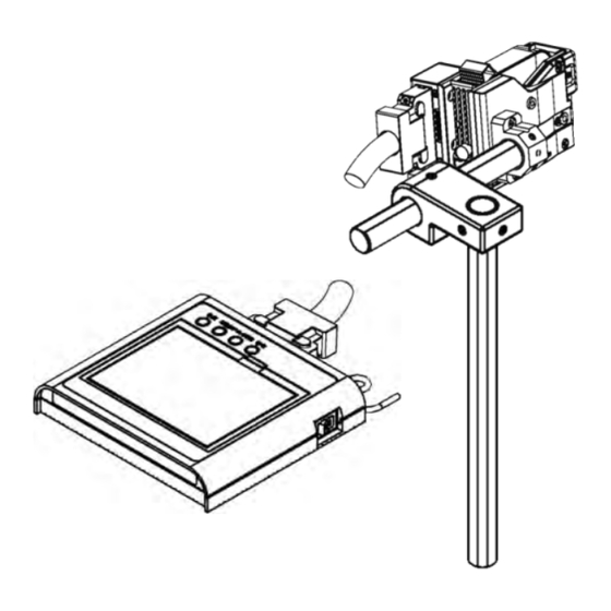
Names of Parts 1-2 ▪ Overall Structure Print head Head cable Controller AC Adapter Expansion Controller (Optional) Name Function Controller It is a device to control print head. (Extended Controller) Print Head Print the letter in printing object (work). Head Cable It is a cable to connect the print head and controller and to drive the print head. -
Page 17: Controller
▪ Controller Ready lamp Ink Refill lamp Power lamp Warning lamp Power switch Touch panel LCD AC adaptor connector Head cable connector Parallel output connector USB Connector ※For details about Optional extension unit part name refer “User manual-I/O version”. Name Function Power lamp It will light up when the power is turned on. -
Page 18: Print Head
▪ Print Head Ink cartridge lever Ejection switch Mode switch Ink cartridge Ejection lamp Nozzle cap Maintenance lamp Ready Light Nozzle Head cable connector Photoelectric sensor connector Name Function Nozzle 300 Ink jet (Nozzle) has been arranged in the range of 12.7mm. When there is no ink spouting for a long time, it is to prevent solidification of the Nozzle cap ink in the nozzle by capping it. -
Page 19: Installation
Installation Installation Procedure 2-1 Operation Reference page p20 "Installation Environment Attention about the installation Confirmation and Important place Point” Confirmation of p21 "Standard Attachment Standard accessory Products” p22 “Tools required for Preparation of tool installation” Installation of the photoelectric p22 "Photoelectric Sensor sensor installation”... -
Page 20: Installation Environment Confirmation And Important Point
Installation Environment Confirmation and 2-2 Important Point Warning Controller and print head are precision instrument, so do not install it at following places. • Places where ambient temperature is not in the range of 5 ~ 35 C (regular) • Places which are extreme tilted &... -
Page 21: Standard Attachment Products
Standard Attachment Products 2-4 This product comes with the below mentioned unit / parts accessories. Name Controller Head Appearance Quantity 1 (Note) Name Head Cable AC - Adaptor Appearance Quantity Name Ink Cartridge Photoelectric Sensor Unit Appearance Quantity 1 Set Name Head mounting Unit Maintenance Set... -
Page 22: Installation Requirements Tools Types
Installation Requirements Tools Types 2-5 Prepare and arrange the following necessary tools before doing maintenance. + Screwdrivers (#1) Hexagonal Wrench (Spanner) (3mm) Scale Paper for print check (cardboard, copy paper, etc...) Photoelectric Sensor installation 2-6 Photoelectric Sensor should be installed in upper fow side of work flow. Do install by referring the diagram and deciding the installation position of photoelectric sensor. - Page 23 (a3) insert the Sensor cable into the gap/ditch of left (b3) insert the Sensor cable into the gap/ditch of right hand side surface of head. hand side surface of head. (a4) plug in the photoelectric sensor connector in the (b4) plug in the photoelectric sensor connector in the back side of head of the photoelectric sensor back side of head of the photoelectric sensor connector.
-
Page 24: Installation Of A Head
Installation of a Head 2-7 (1) Attach a head to a stand with a 3-mm hexagonal wrench (keep a setscrew is one place). A head attachment unit can be attached to a shaft of 20 mm diameter. (2) Tighten the setscrew of a head attachment unit, checking that the direction of a nozzle is perpendicular to the work flow direction. -
Page 25: Installation Of Reservoir
Installation of reservoir 2-8 When using bulk ink, a reservoir must be installed. Install the reservoir by the following method. Settings level adjustment 2-8-1 The setting level varies depending on the ink ejection direction. Fix the shaft according to the dimensions shown below. Make sure the tank is not tilted. Sideways printing Downward printing TEC2977S... -
Page 26: Installation Of A Controller
Installation of a Controller 2-9 (1) Place the controller on even surface, such as a table. It can be put in a tilted way if you pull the leg of back side of the controller (Can be used only when the optional extension unit is not connected) (2) Connect and lock a head cable like the case of a head. -
Page 27: Loading Cartridge
Loading Cartridge 2-10 Check the nozzle cap of a head before loading cartridge. The nozzle cap is set to the position shifted upwards at the time of shipment. ("Normal" state of a lower figure) When the nozzle cap is getting down, pull out before a nozzle cap and shift upwards. - Page 28 Insert the cartridge at a near horizontal angle so that it does not rub against the pins inside the head. Push down on the knob of the cartridge as if you were rotating it around the curved surface at the top front of the cartridge.
-
Page 29: Printing Check
Printing Check 2-11 (1) A printing check is performed. Turn ON the power switch of a controller. (2) If a main screen is displayed, push and return a [menu] button. Push and return a button in order of [a maintenance] and [maintenance] in a menu screen. 1... - Page 30 (5) Change work (including copying paper, the corrugated cardboard piece) for printing confirmation at speed of 16m/m on a conveyer, and when work crosses the direct front of the nozzle, push [printing], and return it. When a conveyer is not available, hold work in a hand and move it at uniformity speed slowly as much as possible, and print it.
- Page 31 (7) When push and go back up, finish test printing. Push [yes,] with a confirmation screen, and go back up. (8) When push this it returns to the [Main] menu screen. Comeback to the main screen. (9) Installation is ended and a power supply is turned off. Push and return [an end] in a main screen, and push and return [yes] in a confirmation screen.
- Page 32 (11) The nozzle is protected.Please protect by the following way. [In cace of TK403Black, TK407Red, TK420Blue, TK421Green (Besides the shock less guard )] Take down the nozzle cap. It pulls out before the nozzle cap and shifts to the front of the nozzle. It is in the right state that a cut and nail of the side of a nozzle cap have geared.
-
Page 33: Fundamental Usage
Fundamental Usage Main Screen 3-1 Name Explanation The name and screen number of a display screen are displayed. A A screen number and a name screen number is used by specification scrolling of p161 “User button”. Status display icon The state, ink residual quantity, etc. of a head are displayed. The time set up by the system clock is displayed. -
Page 34: Status Display Icon
Status Display Icon 3-1-1 Each following item is displayed by an icon. ▪ Operation level The operation level set up by p172 "Operation Level Change” is displayed by an icon. Refer to p162 "Operation Level” for the contents of the operation level. Contents Icon: In an actual display, it is displayed in white. -
Page 35: Icon Button
ICON Button 3-2 Every picture displays well about the application of the button with the ICON. ICON NAME Explanation Setting Button Return to the previous display by deciding the set content. Decide the created (established) content but, not perform the Confirmation Button movement. -
Page 36: Menu
Menu 3-3 Menu Details 3-3-1 Divice to each setting Switch the menu content in left side example button. Return to main screen by using main button. ▪ Copy Setting Perform the detail print setting. Selection state of [Print Setting]. Click the button of item to perform process and move to the respective setting. Items Creating Contents Message Editing... -
Page 37: System Setting
▪ stem setting Set the detailed setups apart from print setting. Selection state of [System Setting]. Click the item button to perform process and proceed with the respective setting. This is displayed in case of expansion controller (option). Items Creation Content System Setting related to other than printing Environment/ Operation... -
Page 38: Current Condition
▪ Current Condition Perform display of current condition and management. Selection state of [current condition]. Click on the button of item that performs process and proceed with the respective process. Items Creating Contents Operation (Management) level Change Operation Level. modification. Copying frequency Display separately the message of copying frequency Operation Document... -
Page 39: Changing The Cartridge Type
Changing the Cartridge type 3-4 For using Cartridge that you haven’t used before, there is a need to perform cartridge settings in the controller. Caution If this setting is not made then there is a possibility of abnormal printing such as input can’t be entered fully or even printing can’t be done. -
Page 40: General Operation Flow
General Operation Flow 3-5 Operation Reference Page Raise nozzle cap p41 "Raise the Nozzle Cap” Put on the Electricity p41 "Switch on the Power” Move the head p42 "Operate the head” p46 "Configuration examples of Create the Message Data message data print conditions”... -
Page 41: Raise The Nozzle Cap
Raise the Nozzle Cap 3-5-1 (1) Raise the nozzle cap in case of nozzle front surface covered by the nozzle cap. Put off on the top before take out of the nozzle cap. Check that the nozzle cap is present in the correct condition state in the position of nozzle perfect exposure position. -
Page 42: Operate The Head
Operate the head 3-5-3 Inorder to allow printing by detecting the work with the head attached photoelectric sensor, the head shall be in the operational state. To make the head as the operating state, return by pressing [Start] on the main screen. Once confirmation message is displayed, click [Yes] to return. -
Page 43: Select The Message Data
Select the Message Data 3-5-5 (1) When the head is in the operating state, the print image that is displayed on the main screen would be printed. Return by clicking the [Selection] icon in the main screen to print other messages. Reference Message selection screen is also accessible from [Menu], [Print Settings] and [Message Selection]. -
Page 44: To Stop The Head
To stop the head 3-5-8 (1) Return by pressing the [Stop]. Once the confirmation message is displayed, return by pressing [Yes]. When it comes to stop state, the ready lamp also goes off. Turning off the power 3-5-9 (1) Returnby pressing [Exit]. When the massage "Do you want to exit the system?"... -
Page 45: 3-5-10 Pulling Down The Nozzle Cap
Note ⚫ Note that data may be corrupted, when the system is ended without appropriate process. ⚫ Ink cartridge may be also damaged. 3-5-10 Pulling down the nozzle cap When printing is not operated for a long time, in order to avoid the solidification of the ink, the nozzle shall be covered with anozzle cap. -
Page 46: Configuration Examples Of Message Data And Print Conditions
Configuration examples of message data 3-6 and print conditions To print out, after creating a message data, the print conditions shall be set up based on the flow of the object concerned (work) to be printed. The step to create the following message data is shown here. The height of entire characters=12.7mm S/N: Text... -
Page 47: Moving To The Message Edit Screen
Moving to the Message Edit Screen 3-6-1 (1) Return by pressing the icon of [Menu] in the main screen. After touching [Print Setting], return by pressing the [Message editing]. After selecting the message number which registration is required, by returning and pressing , the message editing screen would be appeared. -
Page 48: Entering The Printing Data Offixed Characters
Entering the printing data offixed characters 3-6-2 The fixed characters that do not change in printing can be registered by using texts. The text shall be used for the portion surrounded by a broken line as in the following example. Text Module (1) First of all, input [S/N] as text. - Page 49 When the "alpha numeric symbols" is selected in the list of character types, after returning to the text editing screen, the character type would be switched to "alpha numeric symbol". Either single-byte or double-byte can be chosen with . Single-byte input is shown here. Single-byte Double-byte The character is input after returning by pressing the...
- Page 50 If any character is entered wrongly, after selecting the wrong character, it can be deleted after returning by pressing the Delete button at the right end. Subsequently, the size of the characters entered shall be set by pressing the "style" tab. (10) When the character size and the number of the displayed column are pressed, the character size option that can be selected would be presented.
- Page 51 (12) After returning by pressing , data that has entered up to the present would be registered in the text. Once confirmation message is appeared, it shall be returned by pressing the "Yes". Reference It is also possible to be re-edited after registering once. After pressing , select the point where edition is required, and press...
-
Page 52: Entering The Numbering Print Data
Entering the numbering print data 3-6-3 If the count needs to be renewed each time of printing such as product serial numbers, the numbering function can be used. Numbering (1) After selecting , then position which the numbering is required shall be chosen on the canvas. It moves on to the numbering edit screen. - Page 53 After by pressing , restore by pressing "Yes" on the confirmation screen. After pressing , the placing position can be adjusted by dragging on the canvas. TEC2977S...
-
Page 54: Entering The Print Data Of Date Time
Entering the print data of Date Time 3-6-4 When the date and time is printed, the calendar can be used. The date and time that a certain amount of time (offset) was added to the current date and time can be printed in the calendar. - Page 55 In the calendar, the date and time that the offset time was added to clock time date would be printed. When the expiration date is printed, the offset shall be chosen. Press the number of the column of "year/month/ day" of the offset. Enter the "0/0/180"...
- Page 56 (11) Enter the "D1D2/m1m2/Y1Y2Y3Y4" in the calendar editing screen. (12) In order to print the current date and time, the offset setting of "date and time" tab can be remained as an initial value of zero without making any changes. (13) Once the character size was changed to 1/4 at “Style”, register after returning by pressing (14) After pressing...
-
Page 57: Entering The Print Conditions
Entering the print conditions 3-6-5 To print to a desired position on the work, or to print a character desired width, the print conditions shall be set. (1) Return by pressing the "print conditions" button on the menu screen. In the setting screen of print conditions, each setting item shall be set according to necessity. -
Page 58: Regarding The Printing Data
Regarding the printing data The followings can be printed 4-1 Various requirements Suitable functions Reference Message selection To switch the printing content. p59 Message selection function To refer to particular information, while Comment function p110 Comment the printing contents are switched. To print particular characters. -
Page 59: The Message
The Message 4-2 Set the data to be printed as message. ・ Can save up to 1000 messages. ・ Create the print data by posting the printing contents (module) such as texts, calendar etc in the message. ・ Can register up to 32 kinds of modules in 1 message. ・... -
Page 60: Message Edit
Message edit 4-2-2 ▪ Edit Message option Select the message to be edited. ・ Can select while watching the (possible to Maximize or Minimize) print image. ・ Option for assigning the number is also possible. ・ Copying the entire message and deleting is implemented by this window. By the arrow marks mentioned, select the replacement number. -
Page 61: Message Edit
▪ Message edit Edit the message number selected by the message selection. By arranging the contents of the print (Modules) here, it is considered as print data. In other words, editing of the message has the same meaning of that of module arrangements. Title Description MENU for editing. -
Page 62: Message Edit Menu And Icon
Touch the location where you want to place the Message creation area. Edit the module to be placed. Repeat 1-3 and make necessary printing data. When the creation is completed, Press the OK button and go back, edit and complete and, return back to message selection window. ATTENTION Because of possible error during internal processing, the details of the layout may be different between the appearance on the screen and the printed contents. - Page 63 Selection Set the module placed in the message edit area. As for the set module, a frame is displayed. Press this and then press the edited module. Set condition In the entire module, frame is displayed. Both red frames and green frames represent the following respectively.
- Page 64 SCROLL Can scroll to left or right by dragging the message editing area when in this mode. Bring the message by dragging to the right and towards back, and scroll to the top of the message direction by dragging to the left. In order to accelerate the processing speed, the modules that are arranged to display only gray border at this time.
- Page 65 DELETE Delete the module selected. Select the module to be deleted. Module is enclosed in a frame when it is selected. Delete Confirmation pop up is displayed. Check the contents of the display and, delete it if it is OK and, go back to the previous window.
- Page 66 COPY - PASTE The assigned module can be copied and pasted. Select the module to be copied. Module is enclosed in a frame when it is selected. Copy by this. Paste by this. Got pasted. Pasting position is arranged to overlap the module that was copied. Move to the point where it has to be placed.
- Page 67 Property of the message. Set the side direction size of the message. When it is required to print the width with the fixed length, the width size can be set in dot value (Decimal value). At this time, the data jutting (protruding) out than the set size cannot be printed. Setting items Description Now, create either the width size in auto mode or cut it by the designated size.
-
Page 68: Module
▪ MODULE In this condition, by if the message edit area is touched, it will transfer to module edit. ICON DESCRIPTION Text module Calendar module Numbering module Bar code module Should be arranged 2 Secondary original code module Graphic module Interval mode ▪... - Page 69 Change the Module Into Shared Module Explain the procedure to register the module which is placed in the message with a shared module. Set the module which will be changed into Shared module. In case of ordinary module, the selection will be represented by a red line as shown here.
- Page 70 Cancel the shared module and change into general module Explain the procedure to usually change the shared module placed in the message editing to the general module. Set a module for cancelling or removing a shared module. In case of Shared module, the selection will be represented by a red line. Touch the "Sharing"...
- Page 71 Module Selection Mode Explain the procedure for placing the Shared module. CHANGE the message edit mode I to module select mode. If the mode is changed once, the same mode has to be maintained till the mode is changed the next time. Touch “Sharing”...
-
Page 72: Grid
▪ GRID Selects how to place each module. This can be done only by the menu. CONTENTS DESCRIPTION Free Can be placed freely. 1 row 2 rows Selects the direction of dividing the height and length by which line is done by this. 4 rows GRID DISPLAY When it is free... -
Page 73: Message Setting Procedure
Message Setting Procedure 4-2-4 As an example, the following steps (procedure) show how to register text module called "123" in message number 4 with BRG Gothic font and of size 2/4. When the MENU is pressed to return back, it will get transferred (MOVE) to the menu. - Page 74 Then touch the style tab, and go to the Edit Style. Touch the font type, and then change to BRG Gothic. Touch the character size and then change to 2/4. Complete the setting by , and return to the message editing. When the confirmation pop-up appears, touch [Yes] to proceed.
-
Page 75: Text Module
Text Module 4-3 This module is used to print the fixed character string (character string which doesn’t change during printing. ・ It can store up to 4000 characters. Out of 4000 character, 400 character is used as the shared module. ・... -
Page 76: Calendar Module
Calendar Module 4-4 This module is used for printing while updating the date and time automatically. ・ This module can store upto 200. 50th one is used as the shared module. ・ Maximum 256 characters can be registered in 1 module. ・... -
Page 77: Date
▪ Date Edit the date of calendar module. Set by pressing the setting column of each item. Complete the settings by pressing left hand side “OK” symbol and return to the message editing. Return to the message editing without implementing any settings by pressing right hand side “X”... -
Page 78: Details
▪ Details Conduct the detailed settings of calendar module. This setting affects the calendar calculation. Conduct the setting by pressing setting column of each item. If the setting button is pressed, character allocating setting screen of the selected number is navigated. Complete the settings by pressing left hand side “OK”... -
Page 79: Shift
Reference ・ When manual mode is selected at the update mode, content is not updated automatically during printing work. Let the “calendar update of message” of user button get displayed in the main screen and update if it required. Refer to p161 "User button”. ・... -
Page 80: Calendar Symbol
Calendar Symbol 4-4-3 Date or time inside the calendar module is represented by the calendar symbols. The symbol ■ inside the printing content is replaced position of calendar symbol. Symbol Content Printing content Symbol Content Printing content Christian calendar In 2013/04/21 Time (24H system) To be described... - Page 81 DT (1st, 2nd and last ten days of month) Print the 1 character which has divided one month into 1st ten days, 2nd ten days and last ten days. & last ten days ten days ten days Last ten days Period 1-10 days of each month 11-20 days of each month 21-till last days of each month...
- Page 82 SC (Shift Code) Split 1 day into maximum 24 hours and print maximum 16 characters in each hour (shift). Initial value is not set (nothing is printed). Time Line Printing Content 0:00~5:29 Example 5:30~11:59 12:00~18:29 18:30~23:59 SX ( Seconds) Print the seconds. Seconds Initial setting Seconds...
- Page 83 DN (Date number) Date number is a number which is known as Julian number. 1 January is assigned as “001” in the unit of day. It is printed in 3 digits. It is calculated based on the date time of the calendar module being set. It returns back to “001” if the year changes.
-
Page 84: Offset Calculation
Offset Calculation 4-4-4 Offset calculation should be executed in following process order. (1) Add the “minutes” of offset to the “minutes” of clock date and time. If the added result exceeds “60” then fix the “hours” as +1. (2) Add the “hours” of offset to the “hours” of clock date and time. If the added result exceeds “24” then fix the “days” as +1. -
Page 85: Numbering Module
Numbering Module 4-5 This module is used in printing the numbering data (data which updates count during each print). ・ It can store up to 200. 50th one is used as the shared module. ・ It can be placed anywhere in the message. ・... -
Page 86: Detail
▪ Detail Edit the detailed setups of the numbering module. Conduct the setting by pressing settings column of each item. Character allocating setting screen of the selected number is navigated if setting button is pressed. Complete the settings by pressing left hand side “OK” symbol and return the message editing. -
Page 87: Style
Conduct the setting by pressing settings column of each item. Each item gets reset if the reset button is pressed. Complete the settings by pressing left hand side “OK” symbol and return the message editing. Return to the message editing without implementing any setting by pressing left hand side “X”... -
Page 88: Numbering Settings
Numbering Settings 4-5-3 ▪ Number of Digits Numbering at the digits between 1~10 can be done. Number of digits Value: 0 000000 0000000000 Value:1 000001 0000000001 Print ↓ ↓ ↓ ↓ ↓ ing image Value:9 000009 000000009 Value:10 000010 0000000010 ▪... -
Page 89: Reset While Updating Date
▪ Base Calculation method is selected in a range of base 2 to base 38. Initial value is base 10. n Base Printouts 1110 1111 10000 ▪ Reset While Updating Date When the system clock has updated date that time it can be set whether return to the initial value numbering value or not. -
Page 90: Update Mode
▪ pdate Mode Set the update mode of numbering in term of automatic or manual update. ・ If the manual mode is selected then calculate the numbering based on the value printed in the last (update while numbering update button is ON). ・... -
Page 91: Bar Code Module
Bar Code Module 4-6 It is a module that is used in order to print the bar code. ・ Conduct the printing of bar code pattern corresponding to the data registered (numbers or symbols). ・ It is also possible to register the module of calendar or numbering in the barcode. In case of variable module, bar code itself changes each time if data changes. -
Page 92: Code Setting
▪ Code Setting Edit the code setting of bar code module. Conduct setting work by pressing the setting column of each item. It is required to edit the start, stop of NW7. Complete the setting at left hand side “OK” symbol and return to the message editing. -
Page 93: Printable Bar Code Type
Printable Bar Code Type 4-6-3 Number of Digits Type Image・ Size 2~32 (Even number of digits) CODE39 1~32 5(Large) NW-7 Not specified 13/8 Digit 1 (Small) CODE128 Not specified 12/7 Digit 14 Digit DataBar Type Bar Type Features Reference Standard If the number of digits is same then it can be 2 level X 2 colors JIS-X-0502... -
Page 94: About Upc
GS1-128(EAN128) Support In GS1-128, A.I’s (application identifier) are enclosed in parentheses. These () are displayed in OCR, but are not included in the code. To do this on this machine, put a “HIDE” characters in front of both “(“ and “)”, in other words, input “HIDE (“, and “HIDE) “. - Page 95 Features Name Description Omni Encoding of14Digit GTIN is possible in this barcode, hence Directional reffered as Standard Code. The height of code has been limited when compared to Truncated Standard type(Truncated Height level) Two line Bar Code Printing(Reduce Print Width) where Print Stacked space is Small.
-
Page 96: Conditions To Print The Barcode
Conditions to Print the Barcode 4-6-4 Following conditions which are supposed to be the prerequisites must be met in order to print the bar code in favorable state. Conditions Content Speed during the work passes through the head before is slow and should not have any changes in speed. -
Page 97: Normal Characters
▪ Normal Characters Type Characters that Can be Registered ITF, EAN, UPC, GS1 DataBar(1D section) CODE39 (SP) NW-7 " & < > \ ` CODE128 (SP) FNC1 " & < > DataBar section) (SP) ▪ Module (Changeable Characters) Following modules can be registered in the bar code. It is required to register the module if the changeable data is to be printed. -
Page 98: Check Digit (Cd)
▪ Check Digit (CD) It is possible to register the check digit (CD) in to bar code. Check digit can be registered into the list unit at the time of entering character string. If the horizontal list which has registered the character string is touched then it changes to the . -
Page 99: 2D Code Module
2D code module 4-7 This module is used in printing the 2D codes. ・ Conduct the printing of pattern corresponding to the data registered (numerals, symbols). ・ It is also possible to register even the module of calendar or numbering in 2D codes. In case of variable module, 2D codes themselves change whenever data changes. -
Page 100: Editing 2D Code Module
Editing 2D code module 4-7-2 ▪ Characters Edit the 2D code modules. Register the character string to be encoded in the 2D codes. Refer to p105 "Character Input” to know about the registration method of character string. Complete the setting at the left hand side “OK” symbol and return to message editing. -
Page 101: Printable 2D Code Types
Printable 2D code types 4-7-3 Types Image / Features Version Linked function Model 2 incompatible 1~40 ECC200 Square shape Data matrix ECC200 Rectangle incompatible shape PDF417 incompatible Types Character/letters that can be registered Standard Reference JIS-X-0510 Full ASCII+ binary Data matrix ISO/IEC 16022 Various modules (vide infra) Check digit (vide infra) -
Page 102: Graphic Module
Graphic Module 4-8 This module is to print the image data of BMP file. ・ It can store up to 100. However, there is a size limitation of storage area for the BMP file therefore 100 types cannot be stored in case of large BMP file. ・... -
Page 103: Editing Graphic Module
Editing graphic module 4-8-3 ▪ Base dit the graphic module. If the file name displaying area is clicked, it is navigated to file selection screen. If the comment displaying portion is clicked, it is navigated to comment edit. Complete the settings by pressing the left hand side “OK” symbol and return to the graphic module number selection screen. -
Page 104: Interval Module
Interval Module 4-9 This module is used when you want to provide a certain space at an arbitrary position in the middle of the print data. ・ Short space can be fulfilled by even using the blank characters but it is applicable in such a case when the length of space is long and the number of characters is not sufficient or accurate distance is required. -
Page 105: Interval/Pitch Range
Interval/Pitch range 4-9-3 Set the start position by setting the specified printing space. Set the above mentioned space value in the range. Process Features Measure the distance on interval module ・ Printing is possible while retaining the space Interval/space positioning point and start the next between positioning point and start point printing. -
Page 106: 4-10-2 Character Input Screen
4-10-2 Character Input Screen It describes the keyboard to be used for character input (letter input screen). Name Description Character/letter string input Character/letter registered as the Character string is displayed. column It displays the next message input position. In a case 1 Character/letter Cursor has to be deleted then move the cursor till Character/letter and delete. -
Page 107: Keyboard For Normal Character/Letters
Reference ・ Space can be entered by any keyboard. ・ Switching to full width or half width Character/letters through the keyboard having only the full width Character/letters is valid only in space. It doesn’t mean that full width Character/letter will forcibly be half width. -
Page 108: Keyboard For Special Character/Letters
▪ Keyboard for special Character/letters This is a keyboard exclusively used for special module. Mainly it is used in entering the variable Character/letters. Types Screen Description Page count This is the keyboard used in entering the calendar Character/letters. Calendar Character/letter Content of the calendar Character/letter that is pressed is shown at the bottom. -
Page 109: Description Of Bar Codes, 2D Code Character/Letter Input
Note ・ Enter a control code “Fnc1” at the beginning of a data matrix to encode one based on GS1. ▪ Description of Bar codes, 2D code Character/letter input Character/letter string input of bar code and 2D codes is executed at the field unit. Consequently, Character/letter tab of above mentioned two types of modules displayed as in the screen below. -
Page 110: 4-10-3 Comment
4-10-3 Comment It is possible to enter comment depending on the settings. ・ It is recommended to set something like a comment which can give the hint while selecting the settings. ・ Maximum 31 Character/letters can be registered. ・ Comment registration is navigated if comment registration area of the following each setting is clicked. Setting item Associated page. -
Page 111: 4-10-4 Process Order For Character/Letter Input
4-10-4 Process Order for Character/letter Input Following is an example of the Character/letter string registration procedure of the module the same is registered as the "12-34 Ababa I u e ka". Switching to full width is the state of full width Character/letter Register the numerical value "12". - Page 112 Enter "AB". Switch to half width or lower case in order to enter the full width "ab". is the state of lower case letters. Enter "ab". Switch the Character/letter types in order to enter "AI". Select Hiragana from the selection list of Character/letter types. Enter "あい".
- Page 113 Enter "オカ". Execute the settings as input is complete. Confirmation pop up is displayed. Touch "YES" and confirm. "12-34 ABab あいウエオカ" is now finally set. TEC2977S...
-
Page 114: 4-10-5 Fep
4-10-5 FEP FEP (Front End Processor) is a Japanese input system (Japanese input Front End Processor) or (Japanese input FEP), FEP after the abbreviation, which was used in the past to convert Kana and Kanji while entering the Character/letter string Currently, Japanese input software is mainly known as the IM (Input Method) but the term FEP is being used here. -
Page 115: Style
Style 4-11 Set the style details (font, size, ID etc.) in the message of each module. Conduct the setting by pressing the setting column of each item. Complete the setting at the left hand side “OK” symbol and return to message editing. Cancel the settings at left hand side “X”... -
Page 116: Module And Setting Item
BRG Meichou BRG Gothic KGK Ocr Note KGK Ocr is exclusively used for OCR of bar code but the same should not be used usually. Print the “■” if Character/letters are not registered in the font body. ▪ Character/letter size Select the size of Character/letters to be printed from 4 types. -
Page 117: Dots
▪ Dots Set the number of dots by selecting the "dot specification" in character size. ・ Input for providing Font specification and Character Height. Print target or Bleeding varies from char to char, the following will be the reference value. Font Selected Alphanumeric characters (uppercase) print height 1 mm... -
Page 118: Character/Letter Width
▪ Character/letter width Double width size Character/letters are set in the horizontal to vertical ratio. 100% can be set at 10~300% in a state close to square. Character/letter Image space Character/letter width is half 100% This is standard Character/letter 200% Character/letter width is double Note There are cases when maximum Character/letter width can not be used because of the size of the... -
Page 119: Print Condition
Print condition 4-12 Set the condition at the time of printing message data. Save the print condition of few number of messages in internal. Perform setting in each item tab below. For the following each operation, the items of all tab (base, filter etc.) in the menu becomes the subject. -
Page 120: 4-12-1 Base
4-12-1 Base ere we perform the settings of basic print condition. Set by clicking on the setting column of each item. By clicking on this icon, it was confirmed, but it will not go back to menu. When clicked on icon, complete the setting and return to menu. -
Page 121: Print Position
▪ Print position Print position displays the distance (mm) till starting the print by ejecting the ink from the actual head after receiving the print order. However, the actual print position will be the position different from the set value due to mounting position of sensor or head angle, error in input timing of sensor. -
Page 122: Print Direction / Character/Letter Circumference
▪ Print direction / Character/letter circumference Print direction is either printed from the top of the Character/letter or from the end of the Character/letter. ⚫ Print direction "Regular": Print the Character/letter to be printed from the top. ⚫ Print direction "Reverse": Print the Character/letter to be printed from the end. For Character/letter circumference, it is set as upright or inverted in message unit. -
Page 123: Dpi / Density
▪ DPI / Density Change the Horizontal direction DPI and by extending the space between the print, this setting where changing the horizontal direction DPI and expanding the space in the print is included, is with intention to ease the several limitations. -
Page 124: 4-12-2 Filter Setting
4-12-2 Filter setting Photoelectric sensor is used for performing print start. In normal operation, when work passes from the front of sensor, then only it becomes ON and prints starts, but chattering occurred due to shape or color of work may trigger print trouble. -
Page 125: Off Delay Operation
▪ Off delay operation Reserve the change from photoelectric sensor signal is changed to ON→OFF till the setting distance (time) portion print instruction is changed to OFF. If the photoelectric sensor signal in the setting distance (time) returns to ON then the print instruction continues to be ON and if ON does not returns in the setting distance (time) only then the print instruction changes to OFF. -
Page 126: Defects Due To Chattering
▪ Defects due to chattering In print instruction, photoelectric sensor or external signal are used. If chattering occurs in this signal, there are chances that trouble of no printout, print position deviation, numbering skipping may occur. These occurs due to Character/letteristics of ignoring the print instruction that are entered while print operation (From print instruction input to print position wait and print) of that machine or due to timing of chattering. -
Page 127: 4-12-3 Monitor Setting
4-12-3 Monitor setting Use photoelectric sensor for print start. However, due to breakdown in photoelectric sensor, if it is ON then there are cases where print trouble is triggered due to not able to print as the work got stagnant in front of sensor. Here, to avoid those cases, monitor setting is performed. -
Page 128: 4-12-4 Repetitive Print Setting
4-12-4 Repetitive print setting Usually, if there is print instruction entry, then the message set as per message selection, gets printed this time, but if it is set as repetitive print then it will print for the number that is set in print instruction input for 1 time. Set by clicking on the setting column of each item. -
Page 129: Mode
▪ Mode Set the repetitive method for entering print instruction. Process Repeat print for the specified times after triggering the print instruction. Photocell Trigger Number of prints Print Interval Interval Repeat print for the specified time only when the print instruction is ON. When the print instruction label at the time of print is "OFF", and then decides the process as per the "Immediate stop"... -
Page 130: Print Count
▪ Print count et the frequency of repeat printing. Perform the print for the set frequency. In case of making settings without limitations, process as follows. Print count Print order No limitation Once ~ 9999 times Either put OFF the print instruction level, or While the print instructions are input, When ON terminate the print when printing the... -
Page 131: 4-12-5 Setting Of Print Control
4-12-5 Setting of print control Here, details setting related to print can be done. Click on setting column of each item and set. When clicked on icon, it can be confirmed but cannot return to menu. When clicked on icon, setting is complete and it returns to menu. When clicked on icon, it returns to menu without setting. -
Page 132: For Post Standard Printing
▪ For post standard printing This is used when printing with post standard in case flow direction. Size is not constant and in normal previous standard, it is convenient in case the print position cannot be set. Moving direction of products product reaches to the sensor Print command... -
Page 133: Shared Module
Shared module 4-13 Shared module is a module that can be commonly used by multiple messages. In message edit, only the valid module are created every time in module, but in case of using same contents in multiple messages, it will be created every time. Even in case of copying the message temporarily, module with similar content will be created multiples and it will be crushing some valid module area for no reason. -
Page 134: Detailed Setup
Detailed setup 4-14 Here, the details (Details used in common in multiple message / module) of print data is set. Click on the button of setting details to process and proceeds with the respective settings Item Setting details Bar code style Set the details of bar code 2D code style Set the details of 2D code... -
Page 135: Code Type And Setting Item
▪ Code type and setting item Setting details Explanation Code Code1 Comment Comment against each setting Number switching Select 1 ~ 4 Height Bar height Black 1 (Smallest) / Black 2 Black bar width Black 3 / Black 4 (Boldest) White 1 (Smallest) / White White bar width White 3 / White 4 (Boldest) - Page 136 GS1 DataBar Settings of GS1 DataBar is given below. OCR setting items is same as Code128. Symbol Type Setting Details Explanation Omni Stacked Truncated Stacked Limited Directional OmniDir Comment Comment against each setting ○ ○ ○ ○ ○ Number Switching Select 1 ~ 4 ○...
-
Page 137: Bar
▪ Set the white or bar thickness of bar code module. Generally, each bar or blank is called as element, so it is identical to the element setting. Bar code has total maximum 8 types of bar in combination of black, white, small, bold. Click and set the setting column of each item. -
Page 138: Bearer Bar
▪ Bearer bar Bearer bar means This frame is appended such that the ITF code is enclosed from front, back, top, and bottom. Here the details of that frame are set. Click on the setting column of each item and set. Click on icon and complete the setting and return to the menu. -
Page 139: Ocr
▪ OCR means This is the numeric value that displays the bar content to be printed in bar code lower part. Here, the setting of detailed OCR is performed here. The setting item as per bar code type will differ. Click setting column of each item and set. -
Page 140: Bar (For Gs1 Databar)
▪ Bar (for GS1 DataBar) Select GS1 Barcode type, Click setting column of each item and set. After Settings are done Press to return Back to Menu. If you don’t want to save your settings press return back to Menu. Setting items Description Select the Symbol Type. -
Page 141: Composite (Only For Gs1 Databar)
Composite (only for GS1 DataBar) For GS1 Composite , Click setting column of each item and set. After Settings are done Press to return Back to Menu. If you don’t want to save your settings press and return back to Menu. Setting items Description Composite Type... -
Page 142: Ocr (For Gs1 Databar)
OCR (for GS1 DataBar) The setting of detailed GS1 DataBar OCR is performed here. Setting items varies depending on composite types. Click setting column of each item and set. Complete the setting by clicking icon and return to menu. When clicked on icon, it returns to menu without setting. - Page 143 Examples of locations Setting The length of 2Dimensional-part OCR is: approximately same as Shorter than the linear Ocr division Loacation Longer than the linear one the linear one No OCR Same as before Bottom Forward single line Centering Backward Same as before Top&bottom Forward...
-
Page 144: 4-14-2 2D Code Style
4-14-2 2D code style While encoding (making) a 2D code, a necessary item (setting contents for exclusive use of one of every Code such as size, versions, etc.) is setting. It can be saved 4 types of data in every code type and set it the use data of which number in a bar code module. Push the button of two dimensions code type handling and go back up, and, advance to each setting. -
Page 145: Types And Setting Items Of The Code
▪ Types and setting items of the Code Setting contents (Establishment Explanation PDF417 contents) Comment Comment for each setting ○ ○ ○ Selecting which setting from 1 to 4 Number reshuffling ○ ○ ○ performed Cell size length ○ ○ ×... -
Page 146: Qr Setting The Encoding Condition Details Of The Qr Code
▪ ▪ QR Setting the encoding condition details of the QR Code Pushing the setting column of each item by setting. By pressing OK setting will be completed and will returned to menu. By pressing Cancel it will go back up and will return to menu without setting. -
Page 147: Data Matrix
▪ Data matrix Setting regarding the encoding condition details of the data matrix. Pushing the setting column of each item by setting. By pressing OK setting will be completed and will returned to menu. By pressing Cancel it will go back up and will return to menu without setting. -
Page 148: Pdf417
▪ PDF417 Setting regarding the encoding condition details of PDF417 Pushing the setting column of each item by setting. By pressing OK setting will be completed and will returned to menu. By pressing Cancel it will go back up and will return to menu without setting. -
Page 149: Size
▪ SIZE Setting it about each cell of the two-dimensional cord. Setting contents varies according to a cord type, but setting is necessary with all cords. 。 Pushing the setting column of each item by setting. By pressing OK setting will be completed and will returned to menu By pressing Cancel it will go back up and will return to menu without setting. -
Page 150: 4-14-3 Setting Of The Character Assignment
4-14-3 Setting of the character assignment Setting a character assignment to use when print a calendar numbering module ・ Character assignments cope with multiple letters (four characters, after all registered possible characters than actual character types also available) ・ It can save the data of four types of each, setting the use data of which number in respective module Return by pushing the button of two dimensions cord type handling and advance to respective settings. -
Page 151: Calendar Character Assignment
▪ Calendar character assignment Select a layout number to edit than 1 to 4. Comment setting (up to 31 characters can be registered in the comment). The comment settings recommend that is arbitrary (do not mind even if non-registration), registers contents becoming the hint at the time of selecting in a calendar module. -
Page 152: Numbering Character Assignment
▪ Numbering character assignment When a column is in individual symbol When a column is common symbole Select a layout number from 1 to 4 to editing. Setting comments (up to 31 characters can be register in the comment) The comment settings recommend that is arbitrary (do not mind even if non-registration), registers contents becoming the hint at the time of selecting in a numbering module. -
Page 153: Calendar Sign Group
▪ Calendar sign group Functions/ Explanation features Y1:AD 1,000 rank・Y2:AD 100 place・Y3:AD tens place・Y4:AD first place Year H1:ED (Japanese calendar) tens place・H2:ED (Japanese calendar) First place・YX:Year Month M1:October Month・M2:Month First place・MA:Month Week DW:Day・WN:Week Number D1:day tens place・D2:day First place・DT:Month The upper, middle and late・DC:Day・AC: Nonentity day Code DN:... -
Page 154: 4-14-4 Graphic Registration
4-14-4 Graphic registration BMP file which is configure in the graphics module is registered (Captures) inside the controller. Registerable Image File ・ Only Binary BMP files(If it is binary other than black and white, it will internally convert one color in black & the other color in white). -
Page 155: Detail Instruction
Detail Instruction There is such a function 5-1 When there is This function Reference Power is On & at the same time want to Operating state at the time p156 "System printing” apply automatic operation of power-up Want to reset printing frequency Reset printing frequency p156 "System printing”... -
Page 156: System
System 5-2 Set the detail contents about the system. Please proceed to each setting by pressing the button of item to be processed & then go back. Go back to the menu by Item Settings System printing The system settings related to printing System calendar The system settings for the Calendar System alarm... -
Page 157: System Cartridge
Setting items Explanation Once you turn on the power, It is possible to configure the operating state of the head in advance. Operating state at the time Prohibit: Start in a stop state of power-up Operation: Start in Run state state before termination: Started in the power OFF HQ1000 can also log printing number for each message. -
Page 158: System Calendar
System Calendar 5-2-3 Set the details of the system with respect to calendar printing. Set by pressing the setting column of the item. If you press the button, setting is complete and it will back to menu. If you press the it will return to the menu without any setting. -
Page 159: Environment & Operation
Environment & Operation 5-3 Set the details about the environmental and screen operation. Please proceed to each setting by pressing the button of item to be processed & then go back. Go back to the menu by Setting items Explanation Environment Set the input and display language system. -
Page 160: Screen Operation
Screen Operation 5-3-2 Operation・Set the detailed contents about the screen. Pushing the setting column of each item by setting. By pressing OK setting will be completed and will returned to menu. By pressing Cancel it will go back up and will return to menu without setting. -
Page 161: User Button
User button 5-3-3 When register a function to often used, it can display as a button in main screen. From this button function can be used the immediately. ・ It is selectable to four types. ・ The display contents may display the information in conjunction with the case only for buttons. Pushing the setting column of each item by setting. -
Page 162: Operation Level
Operation Level 5-3-4 It can be set the number of the operation level use number and the usable possible of each separate level. ・ It makes the priority for 5 lable levels optionally in a user. ・ Always operate the maximal level fully (it is being possibility of 2 fully and 1 for result nothing). ・... -
Page 163: Initial Setting Of Each Operation Level When Pushed The Recommended Button And Went Back Up
▪ Initial setting of each operation level when pushed the recommended button and went back up Setting item Level 1 Level 2 Level 3 Level 4 Level 5 Driving. stop Feasible Feasible Feasible Feasible Feasible Message Selecting Non-Display Feasible Feasible Feasible Feasible Message editing... -
Page 164: System Clock
System clock 5-4 As System clock becomes the base of the calendar module, so if there is change in system clock, it will affect the content of the calendar module in printing. If you want to change the system clock, please check the calendar module also. It displays the value input screen by pressing the setting fields for each item. -
Page 165: Extension Settings
Extension Settings 5-5 Extension setting is displayed only when extension controller of option is used and setting in regards to external I/O function becomes possible. Press the button of item that performs the process and return and proceeds with the respective settings. To return to menu, click on button. -
Page 166: Maintenance
Maintenance 5-6 Test / Maintenance function are summarized here. Irrelevant to operation level, they are able to move. Select the item and by pushing back the procedure one can perform the process. Select the process. If the Procedure button is pushed back then the guidance display starts. To return to menu, click on button. -
Page 167: Guidance Screen
Guidance Screen 5-6-1 Below explained is the test print using guidance screen example. Select the process. When procedure button is pushed back, the guidance display starts. When this icon is pushed back, then next guidance is displayed (Advances). When this icon is pushed back, the Termination confirm screen of Test print is displayed. -
Page 168: Backup
Backup 5-7 Performs saving each type of data in USB and reads from USB. This machine is storing the setting data in the usual battery backup. However, if the battery is dead then there is a possibility of losing the stored data. In order to avoid such conditions, we recommend taking a backup externally. Please insert the USB memory in the USB connector of controller. -
Page 169: In Case Of Read
In Case of Read 5-7-1 icon is pushed back, the read data selection screen is displayed. Select read data In case of changing folder, specify the folder. icon is pushed back, then it takes you to specified folder. icon is pushed back, it goes back to the previous folder. Select read data. -
Page 170: In Case Of Write
In Case of Write 5-7-2 In case of write When clicked on icon, the write destination selection screen is displayed. Select write folder When clicked on icon, it goes to specified folder. When clicked on icon, it goes back to previous folder. When clicked on icon, the write confirm screen is displayed. -
Page 171: Data Initialization
Data Initialization 5-8 Initialization of each type of data. Select the data for initialization. When Execute button is clicked, the initialization confirms screen is displayed. To return to menu, click on button. Note When Initialization is performed, the specified data (Set data, print data) gets initialized. It does not go back to the original so caution is necessary. -
Page 172: Operation Level Change
Operation Level Change 5-9 Change the operation level (Authority to operate) ・ In case of selecting the operation authority of upper level from Lower level (authority), one needs to enter the password. ・ Each level details + password are separately set in p162 "Operation Level”. When setting column is clicked, the level selection screen is displayed. -
Page 173: Print Count
Print count 5-10 In this machine, the print count for every message is recorded. Here, the record can be confirmed in list format. Further, reset and edit is also possible to do as option. The print count can be set automatically with the setting method mentioned in p156 "System printing”. Move the cursor with these icons and select the message number to be confirmed (The number displayed in page can specify... -
Page 174: Operation Record
Operation Record 5-11 In this machine, at the time of each type of error and at the time of inserting power, each type of history is recorded. History is divided into work log, alarm log, ink, external I/F, and internal information. The recorded time is recorded as value of system calendar. -
Page 175: Unit History
Unit History 5-12 In this machine, all the history till now of the main body like power ON time, operation time, and print count is recorded. Here it is possible to confirm. To return to menu, click on button. Item Content Power ON time Accumulation of time the power is ON... -
Page 176: System Status
System Status 5-13 Here the software version number or font information displays the current status of this machine. At the time of inquiry, there are cases where the version number needs to be confirmed. In that case, confirm it here. Switch the tab display with the help of button. -
Page 177: Parallel Output
Parallel Output 5-14 In the parallel output, excluding the power lamp at the front surface of controller, signal same as 3 lap is output. The controller side connector uses “JST make MUF-RS10DK-GKXR”. The plug to connect to this connector is “JST make MUF-RS10DK-GKXR”. Even in our company, the cable for connection is prepared. -
Page 178: Auto Spit
5-15 Auto Spit 5-15-1 About Auto Spit For the Purpose of making Decap timing longer, The Auto Spit functionality is added. Depending on the requirement settings can be done as follows, NOTE • Decap time is that when the Head Cap is removed and in idle state for long time and the ink becomes Dry, The Auto Spit option will not allow to become Dry by spitting automatically in particular intervals. -
Page 179: 5-15-2 Auto Spit Setting Method
5-15-2 Auto Spit Setting Method For Using Auto Spit function you need to do settings in 3 places as follows, Auto Spit Basic Settings Make these basic Settings to Enable the Auto Spit option, Press “System” from the Setup Menu. Select “System Auto Spit”... - Page 180 Items Description To Use To Use Auto Spit option Check On the Box, If not those settings will be Disabled. Enter the frequency of spit. Input Range:100~99999[Hz] Frequency Note: The maximum value depends on the ink type, you can not set of exceeding the maximum frequency.
-
Page 181: Auto Spit Setting Conditions
Auto Spit Setting Conditions From End of printing please set the time until the next automatic spit start. Since the value in each work size may be different, it sets in the printing conditions (print control) of each message. Select “Print Condition” from Menu. Select “Control”... - Page 182 Caution ⚫ It can not be set if you do not have the auto spit is turn on to "use" in the basic settings. TEC2977S...
-
Page 183: Auto Spit Alarm Setting
Auto Spit Alarm Setting An Alarm can be implemented until the time Auto spit disappears.。 Press “System” from System Setup Menu Select the “System Alarm”from the screen. Pushing the setting column of each item by setting. By pressing OK setting will be completed and will returned to menu. - Page 184 Caution ⚫ It can not be set if you do not have the auto spit is turn on to "use" in the basic settings. TEC2977S...
-
Page 185: Maintenance
Maintenance Normal Maintenance 6-1 ⚫ If a foreign particle like dust or paper power etc get stuck on nozzle or ink gets solid then normal printing cannot be possible. Clean the nozzle surface by including ion exchange water (purified water) by exclusive wiper paper. ⚫... -
Page 186: Exchange The Cartridge
Exchange the Cartridge 6-3 The remaining volume of ink is displayed on screen upper part of controller. If the remaining volume of ink is 30% or less, then the ink supplement lap blinks. If the ink supplement lamp blinks, then exchange the cartridge immediately. - Page 187 (5) Remove the cartridge. When clicked on icon, the next procedure is displayed. (6) Remove the new cartridge from the box and remove the cover. Touch the icon and display the next procedure. While reusing for long term storage, store the cover till discarding the cartridge.
-
Page 188: In Case Of Dot Dropout
In Case of Dot Dropout 6-4 Generally, on nozzle surface, due to ink drying, foreign particle adhesion, part or whole of dot, the ink cannot be ejected (dot dropout) First try if the dots drop out can be removed by a spit. If it cannot be removed even by spit, then perform the procedure of nozzle surface cleaning, cartridge exchange. -
Page 189: Test Print
Test Print 6-4-2 (1) In a state where the maintenance lamp is off, push the mode Maintenance switch twice. Maintenance lamp will blink. lamp Reference For details about mode switch and maintenance lamp, refer to p191 "Mode Switch and Lamp Light Status”. Test print is possible even with a controller screen operation. -
Page 190: Nozzle Surface Cleaning
Nozzle Surface Cleaning 6-4-3 Even if repeating the spit for few times, if the dot dropout does not get cleaned, then clean the nozzle surface. (1) Either cut the power or change the power to stop state. (2) Using dedicated wiper wipe the nozzle gently from top to bottom. -
Page 191: Mode Switch And Lamp Light Status
Mode Switch and Lamp Light Status 6-5 You would be able to spit, test print or replace the cartridge by just using the ejected switch or mode switch of the head. As you press the mode switch each time, the operation mode switches, the lamp of the three head lights will glow in the corresponding pattern of the operation of the mode switch. -
Page 192: Replacement Of Backup Battery
Replacement of Backup Battery 6-6 ⚫ This product is equipped with a battery for memory backup. Irrespective of the turning on the power, there is a possibility that the data may get erased off when the backup battery expires (about 2 years). Once battery starts working, “76C0H battery level drop”... - Page 193 (6) Old battery will remove from the battery holder. (It can remove by pushing up with insulator stick or finger.) Even if the battery is removed, it can save the data for about eight hours. Caution Please make sure that the battery replacement is done within the eight hours.
-
Page 194: Consumables
Consumables 6-7 Order Consumables 6-7-1 When you place an order for comsumables, please let us know the ordering type and the quantity. Ordering type Descriptions [Cartridge type]-CS 1 cartridge of the specified cartridge type. e.g., TK403-Black-CS [Cartridge type] CP 10 cartridge set of the specified cartridge type. e.g., TK403-Black-CP WIPER 1 BC Wiper EVP-CC... -
Page 195: Detection Of Inconsistent Modules
Detection of inconsistent modules 6-8 Issue 6-8-1 The following error message might be shown on startup. This screen shows that the system has detected module-data inconsistencies. Continuing use might cause the following problem. When you edit the string of a module, the string of another one also become modified or erased. -
Page 196: What To Do
What to do 6-8-3 To solve this problem, push the “Yes” button in the error message screen to erase the contents of inconsistent modules. • Push the “Yes” button to erase the contents of inconsistent modules. • Push the “No” button to go to the main screen without erasing the contents of inconsistent modules. (In this case, the problem will not be solved.) •... -
Page 197: Log
6-8-4 When the system detects module-data inconsistencies and/or you perform the procedure by following the ways of handling errors shown above, the following log code will be recorded. Code Content Condition and coping process 5110H Inconsistent module data found Shows that the system detected module-data inconsistencies. Shows that the system erased the contents of the inconsitent 5111H Inconsistent module data erased... -
Page 198: Warranty
Warranty 6-9 • Warranty period of HQ1000 is one year after delivery. • Given the normal handling repair will be done free of charge within the warranty period, if any failure occurrs because of our installation issues. In addition, in the case of failure applicable to repair under warranty, we cannot guarantee about the damage of those which do not come under company product. -
Page 199: When In Trouble
When in Trouble Q&A 7-1 If you encounter any problems with the operation or when the machine is not working properly, Please confirm the following before contacting us. • • Power does not turn ON LCD Check whether the power cord is connected? does not display Please connect the power cord tightly. -
Page 200: Example Of Print Disorder And How To Address Them
Example of Print Disorder and How to 7-2 Address Them Print Example Possible Reasons and How to Address Them ▪ When it prints doubly and shifted to transverse Are the speed setting of print conditions direction. and the speed of an actual work in agreement. -
Page 201: When Conveyor Speed Is Unknown
When Conveyor Speed is Unknown 7-3 It is required to set the (conveyor speed) accurately to the work moving speed as per the print field conditions. In case if the person in charge for Conveyor speed equipment is unavailable, or if you do not have a device like Tachometer (which can measure the speed), then to estimate the conveyor speed Please follow the below procedure to make the conveyor speed calculations after setting the print conditions. -
Page 202: About An Alarm
About an Alarm 7-4 If an abnormality occurs in the system, an alarm will sound; it will be alarm screen display. In addition, the printing process is interrupted if you want to continue the printing process and to resolve the cause of the abnormality, please pressby pressing the Continue button. - Page 203 Error/History code table 7-5 Code Content Condition and coping process 1100H Power activation It is log for Power-on. 1110H Power-off It is log for Power OFF. 1120H Operation (Work) It is log for operation. 1130H Abort It is log for stop. 1214H Confirm Sum Error Normal stoppage did not occur.
- Page 204 1372H QR: Abnormal mode Please confirm the input. QR: Non creation of Error correction letter 1373H Please confirm the input. string 1380H QR: Bad connection Please confirm the input 1391H PDF417: No Data Please confirm the input. 1392H PDF417:Excess Data Size Please confirm the input.
- Page 205 13C2H BMP file: Abnormal file size File size is abnormal. Please confirm. BMP file: Unusable because vertical dots are Please confirm the vertical size and keep it less 13C3H more than 300. than 300Dot. Number of columns in the horizontal direction is 13C4H BMP file: Horizontal imaging column e greater than the requirement;...
- Page 206 Please register after deleting an unnecessary 13F6H Out of Graphics module storage area message module. Please register after deleting an unnecessary 13F7H Out of Module information storage area message module. Please register after deleting an unnecessary 13F8H Out of style storage area message module.
- Page 207 Cartridge verification failure (Company Not be able to authenticate. It might not be our 7455H record) company cartridge. 7456H Unsupported cartridge has been inserted. Unsupported cartridge It is a system error. 7630H Abnormal font Please contact our nearest sales office. A print command input exceeding the the ON time 7661H Photoelectric sensor monitoring error...
- Page 208 Update file splitting failure: CRC Update file splitting failure: CRC 777CH Update file splitting failure: Parameter Update file splitting failure: Parameter 777DH Update started Update started 777EH TEC2977S...
-
Page 209: Specification
Specification Item Specification Printing method Thermal-style on-demand model Maximum 30.48m/min (600dpi mode) ※changes as per the Character/letter pitch and density settings. Printing speed 300 dpi : Max 60.9m/min Nozzle alignment 300 dot 600dpi Ink eject direction Horizontal, downward Maximum Print 12.7mm Character/letter height Number of Heads... - Page 210 TK420Blue TK421Green 20 ~ 80% RH (Non-condensing) TK423Black TK424Stealth TK404Black Operating environment TK406Black TK416Black 35 ~ 80% RH (Non-condensing) TK417Red TK418Blue TK419Green AC100 - 240V ±10%. 50/60Hz, Below 100W Rated voltage TEC2977S...
-
Page 211: Dimensional Outline Drawing
Dimensional outline drawing (External Dimensions) Controller 9-1 TEC2977S... - Page 212 Controller Extension (Optional) 9-2 TEC2977S...
- Page 213 Head 9-3 TEC2977S...
- Page 214 Index 2 2D code module · 58, 99, 100, 133, 205 B barcode module · 91, 96 button · 29, 33, 35, 36, 37, 38, 50, 57, 61, 62, 79, 87, 89, 90, 106, 109, 118, 119, 134, 144, 150, 155, 156, 157, 158, 159, 160, 161, 162, 163, 164, 165, 166, 167, 168, 169, 170, 171, 173, 174, 175, 176, 186, 187, 188, 189, 199, 202, 206 setting ·...
- Page 215 L lamp maintenance · 188, 189 power · 177 ready · 44, 191 M maintenance · 7, 18, 20, 22, 29, 34, 37, 96, 166, 167, 188, 189 maintenance lamp · 188, 189 message · 2, 31, 33, 35, 38, 40, 42, 43, 44, 46, 47, 48, 51, 54, 55, 56, 57, 59, 60, 61, 62, 63, 64, 67, 68, 69, 70, 71, 72, 73, 74, 75, 76, 77, 78, 79, 85, 86, 87, 90, 91, 92, 97, 99, 100, 102, 104, 106, 110, 115, 118, 119, 122, 128, 133, 134, 155, 157, 161, 167, 173, 176, 199, 202, 205, 206, 209 mode ·...
- Page 216 T test print · 18, 30, 31, 121, 166, 167, 188, 189, 190, 191 text module · 58, 73, 74, 75, 97, 117, 150, 209 U USB · 17, 35, 37, 134, 154, 168, 209 connector · 17, 168 memory · 17, 154, 168, 209 ふ...
- Page 217 Kishu Giken Kogyo Co., Ltd. 〒 641-0015 Wakayama Prefecture Wakayama Nunobiki 466 http://www.kishugiken.co.jp (July 2023) TEC2977S...
Need help?
Do you have a question about the JET HQ1000 and is the answer not in the manual?
Questions and answers