Table of Contents
Advertisement
Available languages
Available languages
Quick Links
Use & Care Guide
Manual de Uso y Cuidado
Kenmore
®
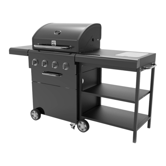
4 Burner LP Gas Grill
Customer Care Hotline
with Side Cart
or order replacement parts
Para pedir servicio de reparación
a domicilio, y ordenar piezas
Parrilla a gas LP con 4
1-844-553-6667
quemadores y carro lateral
www. kenmore. com
Model/Modelo: 152.23151910
®
Sears Brands Management Corporation
Hoffman Estates, IL 60179 U.S.A.
www.kenmore.com
Advertisement
Table of Contents

Related Manuals for Kenmore 152.23151910


Summary of Contents for Kenmore 152.23151910
- Page 1 Para pedir servicio de reparación a domicilio, y ordenar piezas Parrilla a gas LP con 4 1-844-553-6667 quemadores y carro lateral www. kenmore. com Model/Modelo: 152.23151910 ® Sears Brands Management Corporation Hoffman Estates, IL 60179 U.S.A. www.kenmore.com...
- Page 3 These instructions are for your safety. Read them thoroughly before use and retain them for future reference. DANGER: WARNING: If you smell gas: Do not store or use gasoline or other 1. Shut off gas to the appliance. flammable vapors and liquids in the 2.
-
Page 4: Table Of Contents
Parts Supplied Description Illustration Description Illustration Fold-down Cabinet Base Side Shelf Left + Right Vaporising Side Wall Cabinet Cooking Brace Plate Grate Searing Cabinet Grate Front Panel Warming Rack Cross Bar Grease Tray Axle Grease Cup Assembly Bracket Grease Locking Caster Wheel Cart Wheel... - Page 5 Parts Supplied Hardware Supplied Description Illustration Description Illustration M6 x 12 Right Cart Bolt Frame M4 x 10 Cart Shelf Bolt M6 x 45 Cart Rail Bolt Side Cart Hardware items are not shown at actual Handle size. Before You Start Side Cart Check the contents of the box and make sure Tabletop...
- Page 6 Diagram Part List Description Part Number Description Part Number 506 A01 Control Dial 506 A14 Temperature Gauge 506 A02 Grease Tray 506 A15 Logo 506 A03 Grease Cup Bracket 506 A16 Lid Handle Bezel 506 A04 Grease Cup 506 A17 Lid Handle 506 A05 Warming Rack...
- Page 7 Assembly Step 1 M6 x 12 Bolt Cabinet Base Left + Right Side Wall Fit left and right side walls to the cabinet base as shown below using 8 of the M6 x 12 bolts. Note: The right side wall has a hole in the top corner. This is a view from the back.
- Page 8 Assembly Step 2 Cabinet Brace Plate (x2) M6 x 12 Bolt Fit the two cabinet brace plates to the cabinet base and side wall assembly using 8 of the M6 x 12 bolts as shown below. M6 x 12 Bolt Cabinet Brace Plate...
- Page 9 Assembly Step 3 Cabinet Front Panel M6 x 12 Bolt Note: Flip cabinet assembly over so that the left side wall is on the floor. Fit cabinet front panel to base and side wall assembly as shown below using 6 of the M6 x 12 bolts. Note: An extra person will be needed to hold the door in position while tightening the bolts.
- Page 10 Assembly Step 4 Cross Bar M4 x 10 Bolts Fit the cross bar using 4 of the M4x10 bolts. Secure chain to cabinet front panel using the pre-fitted M6 x 12 bolt and washer. Cross Bar...
-
Page 11: Cabinet Base
Assembly Step 5 Axle Assembly Locking Caster M6 x 12 Bolt Wheel (x2) Turn the cabinet assembly over and fit axle assembly and two locking caster wheels to the underside of the cabinet base using 16 of the M6 x 12 bolts. Note: Axle side with cutout goes to back side of cart. -
Page 12: Cylinder Supports
Assembly Step 6 Cylinder Supports M6 x 12 Bolt Turn the cabinet assembly over and fit the two cylinder supports to the cabinet base using 6 of the M6 x 12 bolts. Cylinder Support... -
Page 13: Firebox
Assembly Step 7 Firebox M6 x 12 Bolt Cut the zip ties securing regulator and hose to underside of firebox. Allow hose to hang straight down when lowering firebox onto cart. Position firebox onto cabinet. Open hood and use 4 of the M6 x 12 bolts to secure firebox into position. Be sure that edges of firebox are even with edges of cart before tightening bolts. -
Page 14: Fold-Down Side Shelf
Assembly Step 8 Fold-down Side Shelf Remove the pre-fitted R-clips and pins from brackets on side of firebox. Insert the shelf brackets into the firebox brackets and align the holes. Reinsert pins and clips through the holes to secure the shelf in place. To raise the shelf to use position, lift shelf up and hold it against side of firebox with one hand. -
Page 15: Vaporising Bar
Assembly Step 9 Vaporising Bar (x4) Cooking Grate (x3) Searing Grate Warming Rack 1. Fit vaporising bars (x4) into position as shown. 2. Fit cooking grates (x3) and searing grate into position as shown. 3. Fit warming rack into position as shown. Note: As a convenience feature, there is a bottle opener on the left side of the firebox. -
Page 16: Grease Tray
Assembly Step 10 Grease Tray Grease Cup Bracket Grease Cup M6 x 12 Bolt Attach grease cup bracket to grease tray using one of the M6 x 12 bolts and then slide tray into the back of the grill as shown below. Open the front panel door and slide grease cup into the grease cup bracket as shown. - Page 17 Assembly Step 11 Cart Wheel Bracket (x2) Left Cart Frame Cart Wheel (x2) M6 x 12 Bolt 1. Fit cart wheel brackets to left cart frame as shown below using 8 of the M6 x 12 bolts. 2. Fit the 2 cart wheels to the cart wheel brackets using prefitted bolt and washer attached to the tip of the wheel axles.
- Page 18 Assembly Step 12 Right Cart Frame Cart Shelves (x2) M6 x 12 Bolt Lay the left cart frame down and attach the middle cart shelf first using 2 of the M6 x 12 bolts. Then attach the bottom cart shelf using 3 of the M6 x 12 bolts (Ref A). Then attach the right cart frame to the assembled shelves using 5 of the M6 x 12 bolts (Ref A).
- Page 19 Assembly Step 13 Cart Rail (x2) Side Cart Handle M6x45 Bolt M6 x 12 Bolt Fit the two cart rails to cart frame as shown using 8 of the M6x45 bolts. Note: Be sure to attach the Cart Rails with the wide side facing up. Attach the side cart handle to the top of the right cart frame with 2 M6 x 12 Bolts.
- Page 20 Assembly Step 14 Side Cart Tabletop Utility Bin Chopping Board M6 x 12 Bolt (Ref A) Attach the side cart tabletop to the cart frame using 5 of the M6 x 12 Bolts (Ref A). Place utility bin and chopping board into the side cart tabletop as shown.
- Page 21 Assembly Step 15 To fit the cart to the grill body, lift the cart slightly on the left and lower down to hook onto the grill side brackets. Note: Make sure the side cart wheels are on the left hand side. If you wish to keep the side cart detached, you can remove the side brackets from the grill.
- Page 22 Assembly Step 16 Load gas cylinder into the cabinet through the back, positioning it against the chain between the two cylinder supports, and then securing it by hooking together the two loose chain ends. Connect the gas cylinder to the regulator as shown. Perform leak test (see page 23). Use cabinet front panel for easy access to gas hose and regulator.
- Page 23 Assembly Step 17 NOTE: Leak Test to be performed before using the appliance. Leak Testing Your grill has been checked at all factory connections for leakage. To be performed in a well ventilated area. Confirm all control knobs are in the off position.
- Page 24 SAFETY INSTRUCTIONS • The cylinder used must include a collar to protect the cylinder valve. Warnings • Failure to read and follow these instructions could Do not store a spare LP-gas cylinder under or near result in serious injury or damage to property. this appliance.
- Page 25 Use Instructions - Grill • Never overload the grill with food – evenly space over the cooking grill surface, ensuring sufficient Before proceeding, make certain that you air circulation to the burners. understand the WARNINGS section of this manual. • DO NOT store or cover the grill until fully •...
- Page 26 Manual Lighting Instructions Care and Maintenance • Remove the searing grill and vapor bar from • Regularly clean your grill between uses and barbecue. especially after extended periods of storage. • Place a lit match beside the burner (at the same •...
- Page 27 • The burners should be cleaned annually, or Fig. B whenever heavy build-up is found, to ensure that there are no signs of blockage (debris, insects) in either the burner portholes or the venturi tubes of the burners fitted over the valve outlets. A clogged tube can lead to a fire beneath the grill.
- Page 28 • The gas hose must be connected in accordance with these instructions. When installe parts of the hose should be contained within the Patio Heater pole and gas cylinder c part of hose should be outside of the Patio heater body where it could be a trip hazar accidently damaged.
- Page 29 Grill Specifications Burner 4 Burner Injector Size 1.0 MM Gas/Pressure 11" per W.C Input Rate 11,700 BTU/HR*3 (main) 14,000 BTU/HR*1 (searing) Standard ANSI STD Z21.58-2018 Outdoor Cooking Gas Appliances TECHNICAL AND SERVICING INFORMATION This appliance is designed for outdoor use only using Propane gas at a supply pressure of 11" per WC and must be serviced by a competent person in accordance with the instructions included.
- Page 30 *Rust-through or burn-through must be verified by a Sears authorized service representative. For warranty coverage details to obtain free repair or replacement, visit the web page: www.kenmore.com/warranty All warranty coverage excludes ignitor batteries and grill part paint loss, discoloration or surface rusting, which are either expendable parts that can wear out from normal use within the warranty period, or are conditions that can be the result of normal use, accident or improper maintenance.
- Page 31 Estas instrucciones son para su seguridad. Léalas cuidadosamente antes de utilizar el equipo y guárdelas para futuras referencias. PELIGRO: ADVERTENCIA: Si siente olor a gas: No almacene ni utilice gasolina u otros 1. Cierre la válvula de gas del equipo. vapores y líquidos inflamables cerca de 2.
- Page 32 Piezas provistas Ref. Descripción Ilustración Cantidad Ref. Descripción Ilustración Cantidad Estante Lateral Base del Plegable armario Pared Barra de izquierda + vapor Pared derecha Placa de Parrilla para soporte del Cocinar armario Parrilla de Panel frontal Cocción a la del armario Brasa Rejilla para calentar...
- Page 33 Piezas provistas Componentes suministrados Ref. Descripción Ilustración Cantidad Ref. Descripción Ilustración Cantidad Marco Perno derecho del M6 x 12 carro Estante del Perno carro M4 x 10 Riel del Perno carro M6 x 45 Mango del Las piezas del equipo no se muestran en Carro Lateral tamaño real.
- Page 34 Diagrama Piezas provistas Clave Descripción Cantidad Número Clave Descripción Cantidad Número de pieza de pieza 506 A01 506 A14 Tapa Dial de control Medidor de temperatura 506 A02 Bandeja de grasa 506 A15 506 A03 506 A16 Logo Soporte del recipiente colector de grasa Bisel del mango de la tapa 506 A04 Recipiente colector de grasa...
- Page 35 Ensamblaje – Paso 1 Perno M6 x 12 Base del armario Pared izquierda + Pared derecha Coloque la pared izquierda y la pared derecha en la base del armario (como se muestra abajo), utilizando 8 de los pernos M6 x 12. Nota: La pared derecha tiene un orificio en la esquina superior.
- Page 36 Ensamblaje – Paso 2 Placa de soporte del Perno M6 x 12 armario (x2) Coloque las 2 placas de soporte del armario con el ensamblaje de la base y las paredes, utilizando 8 de los pernos M6 x 12, como se muestra abajo. Perno M6 x 12 Placa de soporte del armario...
- Page 37 Ensamblaje – Paso 3 Panel frontal del Perno M6 x 12 armario Note: Dé vuelta el ensamblaje del armario, de modo que la pared izquierda mire al suelo. Junte el panel frontal del armario con las paredes laterales montadas, como se muestra abajo, utilizando 6 de los pernos M6 x 12.
- Page 38 Ensamblaje – Paso 4 Barra transversal Pernos M4 x 10 Coloque la barra transversal utilizando 4 de los pernos M4x10. Asegure la cadena de la barra transversal a la puerta del panel frontal utilizando el perno M6 x 12 y la arandela preinstalados.
- Page 39 Ensamblaje – Paso 5 Ensamblaje del eje Traba de la Rueda Perno M6 x 12 Pivotante (x2) Dé vuelta el ensamblaje del armario y coloque el ensamblaje del eje y dos ruedas pivotantes en la parte inferior de la base del armario, utilizando 16 de los pernos M6 x 12. Nota: El lado del eje que lleva la abertura va en la parte trasera del carro.
- Page 40 Ensamblaje – Paso 6 Soportes del cilindro Perno M6 x 12 Dé vuelta el ensamblaje del armario. Coloque dos soportes del cilindro en la base del armario utilizando 6 de los pernos M6 x 12. Soporte del cilindro...
- Page 41 Ensamblaje – Paso 7 Cámara de combustión Perno M6 x 12 Proceda a cortar los precintos que sujetan el regulador y la manguera a la parte inferior de la cámara de combustión. Deje la manguera suelta para colocar la cámara de combustión en la parte inferior del carro. Coloque la cámara de combustión sobre el armario.
- Page 42 Ensamblaje – Paso 8 Estante Lateral Plegable Quite los pasadores R preinstalados y barras de metal de los soportes laterales de la cámara de combustión. Coloque los soportes del armario sobre los soportes de la cámara de combustión. Procure que todos los orificios estén alineados.
- Page 43 Ensamblaje – Paso 9 Barra de vapor (x4) Parrilla para Parrilla de Cocción a la Rejilla para calentar Cocinar (x3) Brasa 1. Coloque las barras de vapor (x4) en la posición indicada. 2. Coloque las parrillas para cocinar (son 3) y la parrilla de cocción a la brasa en la posición que se indica. 3.
- Page 44 Ensamblaje – Paso 10 Bandeja de grasa Soporte del recipiente Recipiente colector Perno M6 x 12 colector de grasa de grasa Fije el recipiente colector de grasa a la bandeja de grasa utilizando uno de los pernos M6 x 12, y luego deslice la bandeja por la parte posterior de la parrilla, como se muestra a continuación.
- Page 45 Ensamblaje – Paso 11 Soporte de rueda del Marco izquierdo del Rueda del carro (x2) Perno M6 x 12 carro (x2) carro 1. Coloque los soportes de las ruedas en el marco izquierdo, como se indica abajo, utilizando 8 de los pernos M6 x 12.
- Page 46 Ensamblaje – Paso 12 Marco derecho del Estantes del carro Pernos M6 x 12 carro (x2) Apoye el marco izquierdo del carro en el suelo y empiece montando el estante del medio, utilizando 2 de los pernos M6 x 12. Luego, coloque el estante inferior, utilizando 3 de los pernos M6 x 12. A continuación, junte el marco derecho del carro con los estantes montados utilizando 5 de los pernos M6 x 12.
- Page 47 Ensamblaje – Paso 13 Riel del carro (x2) Mango del Carro Lateral Perno M6 x 45 Perno M6 x 12 Coloque los dos rieles en el marco del carro, como se indica, utilizando 8 de los pernos M6 x 45. Nota: Procure que, cuando fije los rieles del carro, el lado ancho de estos mire hacia arriba.
- Page 48 Ensamblaje – Paso 14 Mesada del carro Contenedor de Tabla para cortar Perno M6 x 12 basura Coloque la mesada en el marco utilizando 5 de los pernos M6 x 12. Coloque el contenedor de basura y la tabla para cortar dentro de la mesada, como se indica.
- Page 49 Ensamblaje – Paso 15 Para ajustar el carro al cuerpo de la parrilla, levántelo ligeramente por el lado izquierdo y bájelo para encajarlo en los soportes laterales de la parrilla. Nota: Asegúrese de que las ruedas del carro miren hacia la izquierda.
- Page 50 Ensamblaje - Paso 16 Coloque el cilindro de gas dentro del armario por la parte posterior. Colóquelo entre los soportes y asegúrelo con las cadenas, enganchándolo a los extremos de estas. Conecte el cilindro de gas al regulador como se indica. Efectúe la prueba de fugas (ver página 23). Utilice el panel frontal del armario para acceder fácilmente a la manguera de gas y al regulador.
- Page 51 Ensamblaje – Paso 17 NOTA: La prueba de fugas debe llevarse a cabo antes de empezar a utilizar el aparato. Prueba de fugas Para descartar fugas, se han efectuado todas las revisiones de fábrica sobre las conexiones del equipo. Le rogamos que efectúe la prueba de fugas en un lugar ventilado.
- Page 52 INSTRUCCIONES DE SEGURIDAD Norma en materia de cilindros, esferas y tubos para el transporte de mercancías peligrosas, según Advertencias corresponda; y • El no leer y seguir estas instrucciones puede causar b. Provisto de un dispositivo de prevención de lesiones graves o daños materiales. sobrellenado;...
- Page 53 Instrucciones de uso - Parrilla • NO utilice gasolina, aguarrás, líquido inflamable, Antes de continuar, asegúrese de comprender la alcohol u otros productos químicos similares para sección de ADVERTENCIAS de este manual. encender la parrilla. • Preparación antes de cocinar: para evitar que los •...
- Page 54 Instrucciones de encendido manual Cuidado y Mantenimiento • Retire la parrilla de cocción a la brasa y la barra • Limpie regularmente su parrilla entre cada uso de vapor de la barbacoa. y especialmente después de largos períodos de • Coloque una cerilla encendida al lado del almacenamiento.
- Page 55 • Los quemadores deben limpiarse anualmente, o Fig. B siempre que haya una acumulación pesada, para asegurarse de que no haya signos de obstrucción (restos, insectos) en los orificios del quemador o en los tubos de venturi de los quemadores instalados sobre las salidas de la válvula.
- Page 56 • Check for leaks by brushing a solution of 50% water and 50% dish soap over the gas including all valve connections, hose connections and regulator connections. • NEVER USE AN OPEN FLAME to test for leaks at any time. •...
- Page 57 Especificaciones de la Parrilla Quemador 4 quemadores Tamaño del inyector 1,0 MM Gas/Presión 11" por W.C Potencia 11.700 BTU/H*3 (principal) 14.000 BTU/H*1 (brasas) Estándar ANSI STD Z21.58-2018 Electrodomésticos a gas para cocinar al aire libre INFORMACIÓN TÉCNICA Y DE SERVICIO Este equipo está...
- Page 58 KENMORE LIMITED WARRANTY CON EL COMPROBANTE DE LA COMPRA, se aplica la siguiente garantía solo en el caso de que este equipo se instale, opere y mantenga correctamente de acuerdo con todas las instrucciones suministradas. POR UN AÑO a partir de la fecha de compra, este aparato está garantizado contra defectos en los materiales o mano de obra.
- Page 60 Kenmore ® Customer Care Hotline To schedule in-home repair service or order replacement parts Para pedir servicio de reparación a domicilio, y ordenar piezas 1-844-553-6667 www. kenmore. com ®...
Need help?
Do you have a question about the 152.23151910 and is the answer not in the manual?
Questions and answers