Table of Contents
Advertisement
Quick Links
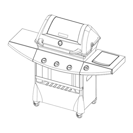
Assembly
and Operation
®
Liquid Propane Gas Grill
Model No. 16238
@
@
I//
THIS GRILL IS FOR OUTDOOR
USE ONLY
CAUTION
Read and follow all Safety
Statements,
Assembly
instructions,
and Use
and Care Manual
Directions
before
attempting
to assemble
and cook.
CAUTION
Some parts may contain
sharp edges,
wear protective
gloves if necessary.
I
Failure
to follow all manufacturer's
instructions
could result
in serious
personal
injury and/or
property
damage.
Customer
Service
Toll Free 1-800-396-3838
To Installer/Assembler:
Leave these
instructions
with consumer.
To Consumer:
Keep this manual for future
reference.
Sears, Roebuck and Co., Hoffman Estates, IL 60179, U.S.A
www.sears.com
SP5327A-37
Advertisement
Table of Contents

Related Manuals for Kenmore 16238


Summary of Contents for Kenmore 16238
- Page 1 Assembly and Operation Liquid Propane Gas Grill Model No. 16238 THIS GRILL IS FOR OUTDOOR USE ONLY CAUTION Read and follow all Safety Assembly instructions, and Care Manual attempting to assemble CAUTION Some parts may contain wear protective gloves if necessary.
-
Page 2: If You Smell Gas
This warranty have other rights which Sears, Roebuck GAS: to the immediately iiiiiiiiiiiiiiiiiiiiiiiiiiiiiiiiiiiiiiiiiiiiiiiiiiiiiiiiiiiiiiiiiiiiiiiiiiiiiiiiiiiiiiiiiiiiiiiiiiiiiiiiiiiiiiiiiiiiiii_i_ on Kenmore Grill Sears will repair or at our option, any grill part (except for paint finish) in material or workmanship. If this grill is defective... - Page 3 For residential use only. Do not use forl commercial cooking, CARBON MONOXIDE Combustion byproducts include carbon monoxide which has no odor and can cause serious injury or death. Never use inside homes, vehicles or tents. Call Grill Service Center For Help And Parts If you have questions or need assistance during assembly, please call 1-800-396-3838.
-
Page 4: Gas Cylinder
1. SPECIFICATIONS Self-contained propane gas grill systems are designed to be used only with a 20 Ib (9.1 kg) propane cylinder, equipped with a Type 1 cylinder valve and incorporating device (O.P.D).THE CYLINDER SHOULD NOT EXCEED 18 1/2"... -
Page 5: Hose & Regulator
BURNER VALVE ON AND LIGHTAS the cylinder for leaks • Never connect a propane gas grill to an unregulated propane gas supply or any other gas. Do not attempt to are not followed alter the hose or regulator in any way. - Page 6 #8-32 x 3/8 Tapping 1/4" - 20 X 2" Carriage #2 Phillips Screwdriver (! piece) #10-24 Wing Nut (Cross Lighter) (3 pieces) :r_._ illivc#_._ & Screw #10 x 1F2Phillips Screw (2 pieces) 1/4" - 20 X 1/2" Carriage (2 pieces )(Black) Bolt 1/4"-20 Large Body Tapered Wing Nut (8 pieces)
- Page 7 NoTank Bracket Left hand leg assembly 1. Turn leg assembly upside down as shown and insert caster plug. Make sure caster plug tab is in line with notch in leg. (SEE FIG "A") 2. Turn leg assembly over and tap on a hard surface until the caster plugs are fully seated.
- Page 8 5. Position left hand leg assembly as shown with console mounting tab facing up. Place non-tank side of bottom pan over bottom support. Attach bottom pan with 1/4"-20 x 1/2" carriage bolt (Black) and wing nut (Black). 6. Position right hand leg assembly as shown, with console mounting tab facing up. Place tank side of bottom pan over bottom support.
- Page 9 7. Position side panels over legs and slide up into position. Bottom flange of side panel hooks over bottom support. Push against leg assembly Then slide up into position...
-
Page 10: Installation
For repair-in your home lawn and garden equipment, no matter For the replacement owner's manuals that you need to do-it-yourself. For Sears professional and items like garage door openers and water heaters. 1-800-4-MY-HOME Call anytime, day or night (U.S.A. and Canada) vvvvvv.sears.com For repair of carry-in items like vacuums, and electronics,... - Page 11 10. Position console/valve assembly over tabs as shown. Locate Console on tabs as shown. (Right side shown) Note: Check wires from switch harness to ensure that they are not against any sharp surfaces.
- Page 12 11. Assemble shelf support brackets by sliding close attention to hole alignment, and attach the two with 13. Attach second shelf support bracet screws. #10 x 1/2Phillips Screw shelf bracket (A) and Shelf bracket (2) #10 x 1/2" screws. using (2) #10 x 1/2" (B) together while paying Repeat...
- Page 13 14. Position left side shelf over shelf mounting Rear View 16. To install shelf trim, tilt grill onto opposite holes in shelf bracket and shelf witht the small place (2) #10 x 1/2" truss head screws shelf) and tighten securely. brackets 15.
- Page 14 18. Attach side burner lid handle, side burner lid and burner tray. 19. First begin by attaching side burner 112" screws. FIG "B" 21. Third, attach side burner lid using (2) #10 Shoulder then insert side burner into slot as shown, bottom of side burner into slot provided.
- Page 15 Front View 22. Attach side burner assemblies using shelf mounting as previously described. (Steps 14 & 15) 23. After attaching side burner base assembly brackets insert side burner valve into burner shown. Side View 24. After inserting valve orifice into burner attach shelf trim using (3) #10 x 1/2 phillips (Steps...
- Page 16 Attach sideburner valveandbezel u sing(2)#8x 3/8tapping screws asshown. Insert s ideburner knob. #8 x 3/8 Tapping Screws Knob Front View 25. Position base casting down over 1/4"-20 studs and secure in place with two 1/4"-20 large body wing nuts. & #8-32 x 3/8 Tapping Screw 1/4"-20 Large Body Wing Nut...
- Page 17 26. Position bottom cross lighter assembly as shown, being sure to feed ignitor wires through the front holes in the bottom of the base casting. Bottom cross-lighter just "lays" loose at this stage of the assembly. NOTE: Cross lighter top and cross lighter bottom assembly come packaged togetherwith the grill burners. These parts should be separated prior to this step.
- Page 18 27.Install b urners byfeeding burner though slotinthebasecasting andguiding burner tubeoverorifice invalve, s eeillustration b elow. S ecure burners withthree1/4"-20 x 3/4"carriage boltsand1/4"-20 Knurl n uts. Burner Tube Orifice Burner tube must fit over valve orifice as shown. 1/4"-20 Knurl Nut 1/4"...
- Page 19 28.Install t hreecrosslighter spacers overthreaded studsin bottom crosslighter, t heninstall c rosslighter topplate. Secure withthree#10-24 wingnuts. Tabs incrosslighter topmustfit into"grooves" ontop ofburners asshown in illustration b elow. #10-24 Wine Cross Lighter Spacer IMPORTANT Tabs in cross lighter top fit into "grooves" on top of burners. Tube Spacer #10-24 Wing Nut...
- Page 20 29.Install H eatDistribution Platebyplacing inposition sothatthesixsupports r estonthesixribsin thebasecasting. Suppo_ Rib in Base Casting...
- Page 21 30.Install L id,Overlay, Handle, Cooking Grid,Warming Rack, H ingeClip,andLogo. Install l idbefore installingoverlay, logo,andtemperature g auge. NOTE: Tighten wing nuts securely.(Do not overtighten) 5. Install temperature gauge. 6. Place handle ends into handle tube as shown Note: Notches in handle tube mate with tab inside handle cap as shown andle Handle...
- Page 22 31.Install g rease trayfromrearof grillbysliding grease trayin onsupport r ailsuntilthe frontofthetraydropsdown overthefrontofthesupport r ails. o oll...
- Page 23 32.Attach thetwowiresfromthecrosslighter andthetwowiresfromthesideburner toanyofthefoursmall t erminals o n ignitor module as shown. Next, A ttach thetwowiresfromconsole assembly t othetwolarge terminals o nignitor module asshown. Important: Be sure to attach wires correctly to terminals. Correct Incorrect NOTE: Use one of the supplied plastic ties to bundle the two large terminal wires together, and one to bundle the four small terminal wires together.
- Page 24 35.Place tankintoholelocated inbottom plate. Insert T ank Bracket intoSlotandrotate it90Degrees. Slide bracket d own overtank ringtohold tankinplace, 36. Connect regulator withtankvalve. Besurethathoseassembly doesnotcontact thebase casting oranyotherparts which willgethot.
- Page 25 Warning: Before proceeding the following steps, ensure you have read the L.P. Gas Cylinder hose and Regulator Assembly and Operation Follow all directions Cylinder filling section of this manual. LIGHTING Prior to lighting your grill, visually check all hoses before each use for nicks, cracking,...
-
Page 26: Breaking In Your Grill
BREAKING IN YOUR GRILL Before cooking on your gas grill for the first time, you should "break it in" by operating it for a short food. To "break in" your grill light the grill following instructions as outlined on the console (see page 25). -
Page 27: Cleaning Venturi Tubes
To keep your grill working at its peak efficiency contribute to the safe operation of this unit, perform operations below at least once a year each cooking season. PERFORM A LEAK TEST A leak test ensures that there are no gas leaks prior to lighting your grill. -
Page 28: Cleaning Other Parts Of Your Appliance
It is possible that very small make webs or nest in the venturi will partially or completely gas through the venturi a smoky yellow flame, is difficult or impossible may cause the gas to burn outside the venturis, cause a fire resulting in damage to your personal... - Page 29 Kenmore P ropane G asGrill REF # PART # SP5051-26 SM5006-1L SP5002-30 SP5028-19 SP5003-16 SP5029-19 SP5000-16 SP5000-17 SM5054-42 SP102A-3G SP18-16 SP5024-20 SP5000-40 SP5026-20 SP5027-20 SP5034-9 SP5006-16 SM5036-9W SP5092-12 SP25-16 SM5001-2L SM5060-9E SM5045-9E SP5012-18 SP5012-16 SP5003-22 SM5023-6E SM5024-6E SM5064-9E SM5243-42E SP5023-18...
- Page 30 :_i.4 :Jlie] J] :1JlvA I :W Kenmore Propane GasGrill...
- Page 31 1. Burners will not light. 2. Flame burns out on "Low" 3. Burners are not hot enough 4. Flame smokey yellow. 5. Console Fire (Flame coming up venturi around console/control knobs). 6. Grease dripping from base 7. Regulator Humming. 8. Burner lights with match,...
- Page 32 For repair-in your home lawn and garden equipment, no matter who made it, no matter who sold it! For the replacement owner's manuals that you need to do-it-yourself. For Sears professional and items like garage door openers and water heaters. 1-800-4-MY-HOME Call anytime, www.sea rs.com...
Need help?
Do you have a question about the 16238 and is the answer not in the manual?
Questions and answers