Table of Contents
Advertisement
Available languages
Available languages
Quick Links
Advertisement
Table of Contents

Subscribe to Our Youtube Channel
Related Manuals for Bosch EKOM 11


Summary of Contents for Bosch EKOM 11
- Page 1 EKOM 11 Installationsanleitung Installation manual...
-
Page 3: Table Of Contents
EKOM 11 Inhaltsverzeichnis Produktbeschreibung Installation Montagehinweise Montagebeispiel Abstandsdiagramm Montageversatz Sender- und Empfängergehäuse Anschaltungen Anschluss Sender an Zentrale Anschluss Glasbruchmelder (4-draht) an Empfänger Anschlussvarianten an Empfänger Technische Daten Table of contents Product description Installation Installation note Installation example Distance diagram Installation offset... -
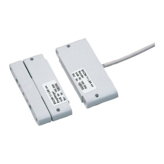
Page 4: Produktbeschreibung
Der Einsatz des Gerätes ohne Speicheranschlußdose ist nach VdS-Klasse B möglich, in diesem Fall dürfen aber nur max. 4 EKOM 11 pro Meldergruppe an einer gemeinsamen Fensterfront verwendet werden. Das 6-adrige Kabel für den Anschluß des Senders zur Einbruchmeldezentrale umfaßt neben den Leitungen für die Stromversorgung, rot=(+), blau=(-), eine 4-Drahtverbindung zum... -
Page 5: Installation
EKOM 11 | de Installation Montagehinweise • Die Montage von Sender und Empfänger erfolgt durch Verschraubung am Montageort. Hierfür stehen auf allen Seiten jeweils zwei Bohrungen am Gehäuse zur Verfügung. Der Montageort ist gemäß der Richtlinie Planung u. Einbau, nach VdS 2311 Absatz 8.2.1.3 zu wählen. -
Page 6: Abstandsdiagramm
| EKOM 11 Abstandsdiagramm [mm] max. Reichweite bei 12 V / +20°C [mm] Montageversatz Empfänger seitlicher Montage- versatz max. 3 mm Sender Sender- und Empfängergehäuse Kabeleinlaß Ø 3,3 Markierung Markierung der Einbaurichtung der Einbaurichtung Ø 3,3 (2x) Ø 3,3 (2x) Empfänger... -
Page 7: Anschaltungen
EKOM 11 | de Anschaltungen Anschluss Sender an Zentrale Anschlusskabel blau blau Vor dem Anschluss sind die Zuleitungen elektrisch zu messen! Anschluss Glasbruchmelder (4-draht) an Empfänger Glasbruchsensoren Anschlussvarianten an Empfänger Anschluss Magnetkontakt Verdrahtung Empfänger oder Riegelkontakt Sabotage- Kabelbinder schleife zur Zugentlastung Empfänger... -
Page 8: Technische Daten
| EKOM 11 Technische Daten Sender und Empfänger Betriebspannung 9 bis 15 V DC zulässige Welligkeit max. 1,0 Vss Ruhestromverbrauch bei 12 V ca. 7 mA (max. 12 mA) Arbeitsstrom ausgelöst bei 12 V max. 22 mA Montageabstand Sender-Empfänger max. - Page 9 EKOM 11 | de Bosch Sicherheitssysteme GmbH Installationsanleitung V1 | 2009.04...
-
Page 10: Product Description
It is possible to use the device without a memory connection box in accordance with Class B VdS; in this case, only a maximum of 4 EKOM 11 units may be used per detector zone on a common bank of windows. -
Page 11: Installation
EKOM 11 | en Installation Installation note • The transmitter and receiver are installed at the installation location by means of screw connections. There are two holes on each side of the housing for this purpose. The instal- lation location must be selected in accordance with the "Planning and Installation" guide- lines, in line with VdS 2311, paragraph 8.2.1.3. -
Page 12: Distance Diagram
| EKOM 11 Distance diagram [mm] Max. range at 12 V/+20 °C [mm] Installation offset Receiver Lateral installation offset max. 3 mm Transmitter Transmitter and receiver housing Cable input Ø 3,3 Mark for Mark for installation direction installation direction Ø... -
Page 13: Connections
EKOM 11 | en Connections Connecting transmitter to control panel Connection cable blue blue The supply lines need to be measured electrically before connection. Connecting (4-wire) glass break connector to receiver glass break sensors Other connections to receiver magnetic contact or... -
Page 14: Technical Specifications
| EKOM 11 Technical specifications Transmitter and receiver Operating voltage 9 to 15 V DC Permissible ripple Max. 1.0 Vpp Operating current consumption at 12 V Approx. 7 mA (max. 12 mA) Open-circuit current triggered at 12 V Max. 22 mA Transmitter-receiver installation distance Max. - Page 15 EKOM 11 | en Bosch Sicherheitssysteme GmbH Installation Manual V1 | 2009.04...
- Page 16 Bosch Sicherheitssysteme GmbH Robert-Koch-Straße 100 D-85521 Ottobrunn Germany Telefon (089) 6290-0 (089) 6290-1020 www.bosch-securitysystems.com © Bosch Sicherheitssysteme GmbH, 2009...
Need help?
Do you have a question about the EKOM 11 and is the answer not in the manual?
Questions and answers