
Related Manuals for Kubota G23-2


Summary of Contents for Kubota G23-2
- Page 1 OPERATOR'S MANUAL MODELS G23-2 G26-2 1BDAFAIAP1570 K2073-7121-1 READ AND SAVE THIS MANUAL - Original instructions -...
- Page 2 ABBREVIATION LIST Abbreviations Definitions American Petroleum Institute Power Take Off Right-hand and left-hand sides are determined by facing in RH/LH the direction of forward travel ROPS Roll-Over Protective Structures Revolutions Per Minute Society of Automotive Engineers...
- Page 3 UNIVERSAL SYMBOLS As a guide to the operation of your tractor, various universal symbols have been utilized on the instruments and controls. The symbols are shown below with an indication of their meaning. Safety Alert Symbol Master Lighting Switch Read Operator's Manual Electrical Power-accessories Hourmeter/Elapsed Operating Hours Headlight-Low Beam...
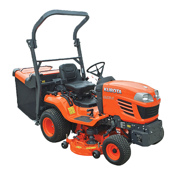
- Page 4 FOREWORD You are now the proud owner of a KUBOTA RIDING MOWER. This machine is a product of KUBOTA's quality engineering and manufacturing. It is made of excellent materials and under a rigid quality control system. It will give you long, satisfactory service.
-
Page 5: Table Of Contents
CONTENTS SAFE OPERATION .................... SERVICING OF RIDING MOWER ................1 SPECIFICATIONS....................... 2 IMPLEMENT LIMITATIONS ..................4 INSTRUMENT PANEL AND CONTROLS..............6 MOWER MOUNTING ....................7 ATTACHING THE MOWER ..................7 Mounting the Mower Deck ....................7 ADJUSTING THE MOWER DECK (FRONT TO REAR)........10 ADJUSTING THE MOWER DECK (SIDE TO SIDE) .......... - Page 6 CONTENTS Stopping.......................... 25 CHECK DURING DRIVING ................... 25 Immediately Stop the Engine if: ..................25 Easy Checker (TM)......................25 Fuel Gauge ........................26 Coolant Temperature Gauge ..................26 Hourmeter / Tachometer....................27 PARKING ....................... 27 Parking..........................27 Hydrostatic Transaxle Bypass Button................28 OPERATING TECHNIQUES .................
- Page 7 CONTENTS Engine Cover ........................46 DAILY CHECK ....................... 47 Checking Engine Oil Level....................48 Checking and Refueling....................49 Checking and Cleaning Panel and Radiator Screen ............49 Checking Tire Pressure ....................50 Checking Transmission Fluid Level ................50 Checking Coolant Level....................51 Checking Movable Parts....................
- Page 8 CONTENTS Replacing Mower Gear Box Oil Seal ................76 Replacing Intake Air Line....................76 SERVICE AS REQUIRED..................76 Replacing Fuses ......................76 Replacing bulbs ......................77 Checking and Replacing Blade..................77 Replacement to New Shear Pins..................79 Checking and Adjusting Jump Plate ................79 Bleeding Fuel System.....................
- Page 9 Use a spark arrester where required. Also keep the 18. Use only attachments recommended by KUBOTA. engine and muffler clean all the time. Replace the Use proper ballast to front or rear of machine to reduce muffler if it has a fault.
- Page 10 SAFE OPERATION 3. Never try to get on or off a moving machine. 17. Never leave a running machine unattended. 4. When using any attachments, never direct discharge Always turn off blades, set parking brake, stop engine, material toward bystanders. Do not allow anyone near and remove the key before dismounting.
- Page 11 PTO-driven equipment. over the edge of a cliff or ditch, or if an edge caves in. 3. Use the PTO with KUBOTA approved attachments. 4. Do not mow on wet grass. Reduced traction could cause sliding.
- Page 12 If a part to be replaced has a sign on it, obtain a new safety sign from your KUBOTA Dealer and install it in the same place as on the removed part. 7. Use extra care in handling diesel fuels. They are flammable.
- Page 13 Please dispose properly. 29. See your local Recycling Center or KUBOTA Dealer to learn how to recycle or get rid of waste products. A A Material Safety Data Sheet (MSDS) provides specific details on chemical products;...
- Page 14 SAFE OPERATION 7. STORAGE 1. Keep the machine and supply of fuel in locked storage and remove the key to prevent children or others from playing or tampering with them. 2. When machine is to be stored for a long time, disconnect battery cables or remove the battery.
- Page 15 SAFE OPERATION 8. PICTORIAL SAFETY LABELS...
- Page 16 SAFE OPERATION...
- Page 17 SAFE OPERATION...
- Page 18 SAFE OPERATION...
- Page 19 SAFE OPERATION...
- Page 20 2. Clean pictorial safety labels with soap and water, dry with a soft cloth. 3. Replace damaged or missing pictorial safety labels with new labels from your local KUBOTA Dealer. 4. If a component with pictorial safety label(s) affixed is replaced with new part, make sure new label(s) is (are) attached in the same location(s) as the replaced component.
-
Page 21: Safe Operation
When in need of parts or major service, be sure to see your KUBOTA Dealer. When in need of parts, be prepared to give your dealer the serial number of the machine, engine and mower. -
Page 22: Specifications
SPECIFICATIONS SPECIFICATIONS G23-2 G26-2 Model Model D902 D1005 Type Liquid-cooled diesel Total displacement 1001 Gross power 17.1 18.8 No. of cylinders Engine Starter Electric starter with battery Battery 526RMF (12V, RC:80 min, CCA: 540A) Diesel fuel No.1 (below -10 Fuel Diesel fuel No.2 (above -10... - Page 23 SPECIFICATIONS Model RCK48-G23-2 RCK54-G26-2 Cutting width 1219 1372 Cutting height 25 to 102 Adjustment of cutting height Dial gauge Mounting method Quick joint, Parallel linkage Weight (Approx.) Mower Total length Dimensions Total width 1266 1418 Total height Discharge direction Rear...
-
Page 24: Implement Limitations
Use of implements which exceed the maximum loading weight listed below, or which are not recommended for use with the KUBOTA Machine may result in malfunctions or failures of the machine, damage to other property and injury to the operator or others. (Any malfunctions or failures of the machine resulting from use with improper implements are not covered by the warranty.) - Page 25 Add ballast to rear end if needed for stability. Heavy front mounted attachments tend to lift rear wheels. Add enough ballast to maintain steering control and prevent tipover. The Attachment's Manual shows how much rear ballast is required for your application. Rear ballast are available from your KUBOTA Dealer.
-
Page 26: Instrument Panel And Controls
INSTRUMENT PANEL AND CONTROLS INSTRUMENT PANEL AND CONTROLS (1) Easy checker(TM)........25 (2) Coolant temperature gauge......26 (3) Horn button..........21 (4) Turn signal light switch (works if light is equipped)......17 (5) Head light switch......... 21 (6) Fuel gauge..........26 (7) Hourmeter.......... -
Page 27: Mower Mounting
MOWER MOUNTING MOWER MOUNTING ATTACHING THE MOWER To avoid personal injury: A Shut off the engine and remove the key before attaching the mower. BMounting the Mower Deck 1. Park the machine on level ground and place the mower deck at the left side of the machine. 2. - Page 28 MOWER MOUNTING 7. [Model with the universal joint cover] A Finally pull the universal joint to check if it is tight in Install the back cover 1 with the two bolts on the left position. side, and a bolt on the right side. Install the back cover 2 with the two bolts, and then make sure that the pins are inserted to the holes of the universal joint cover.
- Page 29 MOWER MOUNTING 10. [Model with the universal joint cover] 13. Turn the cutting height control dial to 0 position. Install the front cover with the two bolts, and then make Place the mower lift lever in the "DOWN" position. sure that the pins are inserted to the hole of the Push down the link arms to align with the mower universal joint cover.
-
Page 30: Adjusting The Mower Deck (Front To Rear)
MOWER MOUNTING 16. Shut off the engine. ADJUSTING THE MOWER DECK (FRONT TO REAR) To avoid personal injury: A Shut off the engine and remove the key. A Set the parking brake. A Allow the blades to stop before making adjustments. -
Page 31: Dismounting The Mower Deck
MOWER MOUNTING DISMOUNTING THE MOWER DECK 1. Raise the mower deck to the top position. For installation and uninstallation, set the anti-scalp rollers (Front) as shown the figure below. Then make sure that the clevis pins are set into the lower holes of front anti-scalp rollers. -
Page 32: Grass Catcher Mounting
GRASS CATCHER MOUNTING GRASS CATCHER MOUNTING ATTACHING THE GRASS CATCHER 3. Slide the lower pins into the hook. To avoid personal injury: A Shut off the engine and remove the key before attaching the grass catcher. A Set the parking brake. <High Dump>... -
Page 33: Dismounting The Grass Catcher
GRASS CATCHER MOUNTING 5. Attach the couplers to the hose with the same color tag. BDismounting the grass catcher For dismounting the grass catcher, reverse the above procedures. <Low Dump> BMounting the bag 1. Park the machine on a level ground, shut off the engine and remove the key. -
Page 34: Dismounting The Grass Catcher
GRASS CATCHER MOUNTING 5. Turn the lock levers to inside of the machine. A L pin must be in unlock position. A When L pin are unlocked, the pin lock labels can be seen from outside. When L pin are locked, the pin lock labels can not be seen from outside. -
Page 35: Operating The Engine
OPERATING THE ENGINE OPERATING THE ENGINE 1. When parking, be sure to set the parking brake. To set the parking brake; (1) Depress the brake pedal. To avoid personal injury: (2) Latch the brake pedal with the parking brake lock A Read and understand "SAFE OPERATION"... - Page 36 OPERATING THE ENGINE 3. Sit on the operator's seat and adjust the 5. Insert the key into the key switch and seat position. turn it "ON". C Check Easy Checker(TM) Lamps; When the key is turned "ON", lamps (2) (3) (4) (5) (6) only should come on.
-
Page 37: Key Switch
OPERATING THE ENGINE 7. Turn the key switch to the "START" BKey Switch position and release when the engine starts. OFF....The position where the key can be inserted into or removed from the key switch. [When the key is turned to A Because of safety devices, the engine will not start this position, the engine stops the except when the speed control pedal is in the... -
Page 38: Warming Up
A If noises are heard after the hydraulic control lever has been activated and the implement is lifting, the hydraulic mechanism is not adjusted properly. Unless corrected, the unit will be damaged. Contact your local KUBOTA Dealer for adjustment. (1) Dead battery (2) Jumper cables (3) Engine block or frame (4) Helper battery Connect cables in numerical order. - Page 39 OPERATING THE ENGINE A This machine has a 12 volt negative (-) ground starting system. A Use only same voltage for jump starting. A Use of a higher voltage source on machine could result in severe damage to machine electrical system. Use only matching voltage source when "Jump starting"...
-
Page 40: Operating The Machine
OPERATING THE MACHINE OPERATING THE MACHINE OPERATING NEW MACHINE How a new machine is operated and maintained will To avoid serious injury: determine the life of the machine. A Do not allow any person other than the driver to A new machine just off the factory production line has ride on the machine. -
Page 41: Starting
OPERATING THE MACHINE STARTING 2. Select the light switch positions. 1. Adjust the operator's position. BHead Light Switch Turn the light switch clockwise, and the following lights are BSeat activated on the switch position. To avoid personal injury: A Make adjustments to the seat only while the machine is stopped. -
Page 42: Mower Lift Lever
OPERATING THE MACHINE [G23-2] 3. Start the engine. To dump the grass, pull the lever BACKWARD (B). See "OPERATING THE ENGINE" To close the container, push the lever FORWARD (A). section. 4. Raise the implement. BMower Lift Lever The mower lift lever is used to raise and lower the mower. -
Page 43: Throttle Lever
OPERATING THE MACHINE 5. Accelerate the Engine. 7. Depress the Speed Control Pedal. BThrottle Lever BSpeed Control Pedal Pulling the throttle lever back increases the engine speed and pushing it forward decreases the engine speed. To avoid serious injury: A Do not operate if the machine moves on a level ground with foot off Speed Control Pedal. -
Page 44: Speed Set Device
OPERATING THE MACHINE BSpeed Set Device The Speed Set Device is designed for the machine operating efficiency and the operator's comfort. This device will provide a constant forward operating speed by mechanically holding the speed control pedal at a selected position. C To engage Speed Set Device 1. -
Page 45: Stopping
: Glow plug indicator (Pre-heating Indicator) When the key switch is in the "PREHEAT" position, the glow plug indicator illuminates. A For checking and servicing of your machine, consult your local KUBOTA Dealer for instruction. (1) Easy Checker(TM) (2) Fuel gauge (3) Coolant temperature gauge... -
Page 46: Fuel Gauge
OPERATING THE MACHINE BFuel Gauge BCoolant Temperature Gauge When the key switch is "ON", the fuel gauge indicates the fuel level. It's for the check if the gauge is working. To avoid personal injury: When the fuel is close to empty level, the low fuel indicator A Do not remove radiator cap until coolant of the Easy Checker(TM) comes on and the segment K1 temperature is well below its boiling point. -
Page 47: Hourmeter / Tachometer
OPERATING THE MACHINE PARKING BHourmeter / Tachometer BParking The hourmeter indicates in six digits the hours the machine has been used; the last digit indicates 1/10 of an hour. When the key is turned "ON", the tachometer should To avoid serious injury: A Always set the parking brake, stop the engine indicate 4000 engine revolutions per minute (rpm) for just and remove the key before leaving the machine... -
Page 48: Hydrostatic Transaxle Bypass Button
OPERATING THE MACHINE OPERATING TECHNIQUES BHydrostatic Transaxle Bypass Button BDifferential Lock A Do not push the machine without pushing the bypass button or transmission damage may occur. A Never push the button with the engine running. To avoid personal injury due to the loss of steering control: 1. -
Page 49: Operating The Mower
OPERATING THE MOWER OPERATING THE MOWER MAKING THE MOST OF YOUR MOWER ADJUSTING CUTTING HEIGHT 1. When using your mower for the first time, choose a smooth level area and cut in straight and slightly overlapping strips. To avoid serious injury or death: 2. -
Page 50: Operating The Mower
OPERATING THE MOWER OPERATING THE MOWER 2. Set the anti-scalp rollers height as shown to keep clearance between rollers and ground more than 6mm. See the table below. 3. Lower the mower deck by pushing the mower lift lever 1. Start the engine. downward. - Page 51 OPERATING THE MOWER (1) PTO lever : "ENGAGED" (1) Knob bolt (A) "OPEN" (Move the cover clockwise) : "DISENGAGED" (2) Cover (3) Slot A To avoid shock loads to the PTO, reduce engine A Slot should be closed on normal operation. throttle from full to half speed by pushing up on engine throttle when engaging the PTO, then re-engage the 4.
-
Page 52: Operating The Grass Catcher
OPERATING THE GRASS CATCHER OPERATING THE GRASS CATCHER EMPTYING THE GRASS CATCHER To avoid serious injury or death: A Do not operate mower without grass catcher. To avoid personal injury: A Raise and dump collected leaves or grass OPERATING PERFORMANCE clippings ONLY while sitting on the Operator's 1. - Page 53 OPERATING THE GRASS CATCHER <Low Dump> 1. Disengage the PTO lever. (1) Grass container control lever (A) "UP" (2) Rear quick clean lever (B) "DOWN" (C) "TILT BACKWARD" (1) PTO lever : "ENGAGED" (D) "TILT FORWARD" : "DISENGAGED" 2. Tilt the grass container with moving the grass container control lever to rear.
-
Page 54: Stopper (High Dump Only)
OPERATING THE GRASS CATCHER STOPPER (High Dump only) BRelease the stopper 1. For release stopper, reverse above procedures. To avoid personal injury or death: A Park the machine on a firm and level surface. A Apply the parking brake. A If it is hard to release the stopper, lift up the grass A Empty the grass container. -
Page 55: Grass Container Net Material
A The grass container net material is subject to deterioration and wear. Check it frequently. Use only genuine replacement net from KUBOTA. A Make sure all shields and guards are securely in place following all service, cleaning, or repair work. -
Page 56: Adjusting The Grass Catcher Sensor
OPERATING THE GRASS CATCHER ADJUSTING THE GRASS CATCHER SENSOR Before mowing, adjust the grass sensor position according to the grass and field conditions. If the more collecting performance is needed, hook the spring toward A. (1) New or cleaned net A Install the L pins as shown below. -
Page 57: Quick Clean Lever
OPERATING THE GRASS CATCHER QUICK CLEAN LEVER BRear Quick Clean Lever BFront Quick Clean Lever The rear quick clean lever is designed for discharging the The front quick clean lever is designed for discharging the grass, which is plugged at the rear of the duct. grass, which is plugged at the outlet of the mower. -
Page 58: Cleaning
CLEANING CLEANING To avoid personal injury: A Do not clean the machine with engine running. A Be sure to set the parking brake during cleaning. CLEANING WITH WATER The use of a high pressure cleaner is not recommended. However if you use one, take care not to splash water on engine parts such as the air filter, exhaust muffler, battery. -
Page 59: Cleaning The Body
CLEANING CLEANING THE BODY CLEANING THE MOWING SYSTEM USING HOSE 1. Clean the grass buildup under battery behind the valve covers. 1. Attach the water hose to the mower joint and turn on water. (1) Valve cover (1) Joint (if equipped) 2. -
Page 60: Tire And Wheels
TIRE AND WHEELS TIRE AND WHEELS TIRES To avoid serious injury: A Do not attempt to mount a tire. This should be done by a qualified person with the proper equipment. A Always maintain the correct tire pressure. Do not inflate tires above the recommended pressure shown in the Operator's Manual. -
Page 61: Maintenance
MAINTENANCE MAINTENANCE SERVICE INTERVALS The following servicing tasks should be carried out on the machine at the stated running-time intervals. Indication on hour meter (Hr) After Ref. Items since page every Engine oil Change 200 Hr every Engine oil filter Replace 200 Hr every... - Page 62 *1 This maintenance should be done daily more often in dusty conditions than in normal conditions. Suggested cleaning interval is every 100 hours in normal conditions. *2 These items should be serviced by an authorized KUBOTA Dealer, unless the owner has the proper tools and is mechanically proficient.
-
Page 63: Lubricants, Fuel And Coolant
..SAE30, SAE10W-30 or 15W-40 0 to 25 ..SAE20, SAE10W-30 or 15W-40 Below 0 ..SAE10W, SAE10W-30 or 15W-40 Transmission case 11 L KUBOTA UDT or SUPER UDT fluid*1 Mower gear box 1.9 L 2.1 L KUBOTA UDT or SUPER UDT fluid*1... - Page 64 MAINTENANCE No. of greasing points Greasing G23-2 G26-2 Capacity Type of grease Front axle (King Pin) Until grease Multipurpose EP2 Grease overflows (NLGI Grade No.2) Front axle (Center Pin) Middle link Brake pedal link HST speed change pedal dumper HST pedal boss...
- Page 65 We recommend the use of KUBOTA UDT or SUPER UDT fluid for optimum protection and performance. (Consult your local KUBOTA Dealer for further detail.) Do not mix different brands together.
-
Page 66: Periodic Service
PERIODIC SERVICE PERIODIC SERVICE BEngine Cover To avoid personal injury: 1. To detach the hood, disconnect the headlight connector and the couplers of the horn, and draw the A Do not work under any hydraulically supported cord clamp out to the hole in the hood post. devices. -
Page 67: Daily Check
PERIODIC SERVICE DAILY CHECK To prevent trouble from occurring, it is important to know the condition of the machine. Check it before starting. To avoid serious injury: A Be sure to check and service the machine on a level surface with the engine shut off, the key removed and the parking brake securely set. -
Page 68: Checking Engine Oil Level
2. Check engine oil before starting the engine or 5 contact your local minutes or more after the engine has stopped. KUBOTA Dealer 3. To check the oil level, draw out the dipstick, wipe it immediately. clean, replace it, and draw it out again. Check to see that the oil level lies between the two notches. -
Page 69: Checking And Refueling
PERIODIC SERVICE BChecking and Refueling BChecking and Cleaning Panel and Radiator Screen To avoid serious injury: A Do not smoke while refueling. To avoid personal injury: A Be sure to stop the engine and remove the key A Be sure to stop the engine and remove the key before refueling. -
Page 70: Checking Tire Pressure
PERIODIC SERVICE A Be sure to reinstall the panel on the pillar completely to prevent the invasion of dust. A Be sure to stop the engine to avoid personal injury and to allow good air intake for air cleaner. BChecking Tire Pressure To avoid personal injury: A Do not attempt to mount a tire on a rim. -
Page 71: Checking Coolant Level
(1) Key switch (4) Hand throttle lever radiator. (2) PTO clutch lever (5) Brake pedal A If water should leak, consult your local KUBOTA (3) Operator's seat (6) Hydraulic container dump lever Dealer. C Safety Start Control 1 1. Depress the brake pedal (5) fully. -
Page 72: Checking Opc System
A If the machine does not pass one of the following tests, do not operate the machine. following tests, do not operate the machine. Contact your KUBOTA Dealer. Contact your KUBOTA Dealer. A Check the following tests before operating the A Check the following tests before operating the machine. -
Page 73: Cleaning Air Cleaner Element
1. Remove the air cleaner cover and element. (1) Undo the hook. (2) Turn the cover clockwise and detach it. (3) [Only G23-2] Turn the cover, and place the evacuator valve on the position as shown in the figure. Take out the cover while pulling the upper edge (1) Element of the engine cover forward. -
Page 74: Checking Gear Box Oil Level
PERIODIC SERVICE BChecking Gear Box Oil Level BGreasing To avoid personal injury: To avoid personal injury: A Always stop the engine and remove the key A Be sure to stop the engine and remove the key before checking oil. before greasing. 1. - Page 75 PERIODIC SERVICE (1) Middle link (LH, RH) (1) Brake pedal link (2) HST speed change pedal dumper (1) Brake pedal link (1) HST speed change pedal dumper (1) Brake pedal link (1) HST pedal boss...
- Page 76 PERIODIC SERVICE (1) Tension PTO arm (1) Cruise control link (1) PTO (Spline) (1) Differential lock pedal link (1) Parking lock pedal link (1) Differential lock pedal link (2) Rear tire (LH)
- Page 77 PERIODIC SERVICE (1) Under duct pivot (2) Sensor system pivot (1) Seat adjuster (1) Duct cleanup system link (1) Seat pivot (1) Duct cleanup system link (1) Mower universal joint (2) Mower universal joint (Grease nipple)
- Page 78 PERIODIC SERVICE (1) Mower lift cylinder (1) Mower lift link front (1) Mower lift cylinder (1) Mower lift arm rear (LH, RH) (1) Mower lift arm front (RH) (1) Mower lift pin front (LH, RH)
- Page 79 PERIODIC SERVICE (1) Mower lift link rear (LH, RH) (1) Grass container rotation pivot (1) Dump cylinder (1) Lock lever (LH, RH) (1) Dump cylinder (1) Grass container pivot (Grease nipple) (LH, RH)
-
Page 80: Oiling
PERIODIC SERVICE BOiling To avoid personal injury: A Be sure to stop the engine and remove the key before greasing. Oil the following locations. (1) Grass container lift cylinder (LH, RH) (1) Throttle cable (1) Dump pivot (LH, RH) (1) Throttle cable... -
Page 81: Battery
Battery Volts Capacity Cranking Charging Type Type (min) Amps Rate(A) G23-2 526RMF G26-2 To avoid the possibility of battery explosion: refillable type battery, follow instructions below. (For non-accessible maintenance-free type batteries.) A Do not use or charge the refillable type battery... -
Page 82: Front Pto Belt Tension
If the front PTO belts slip when the PTO is operating under load, check the front PTO belt tension and adjust the tension spring length, as explained below. [G23-2] 1. Remove the engine cover. (See "ENGINE COVER" in "PERIODIC SERVICE".) 2. -
Page 83: Every 100 Hours
PERIODIC SERVICE EVERY 100 HOURS BChecking Fuel Lines and Fuel Filter To avoid personal injury: A Stop the engine and remove the key before checking fuel lines and fuel filter. A Check the fuel lines periodically. The fuel lines are subject to wear and aging. Fuel may leak out onto the running engine, causing a fire. -
Page 84: Checking Parking Brake
A If you are not able to adjust, consult your local KUBOTA Dealer for this service. A Wrong adjustment may cause machine damage. (1) Fuel pump and filter (1) Check brake spring length (2) Fuel line (3) Pipe clamp 1. - Page 85 (B) "Move the brake lever" (3) Brake lever (P) "Parking brake spring play" (4) Link arm (5) Brake rod (6) Plain washer 8. If the brake spring length or play is not correct, consult your local KUBOTA Dealer for this service.
-
Page 86: Adjusting Fan Belt Tension
1. Stop the engine and remove the key. step can adjust returning speed of speed control pedal. 2. Apply moderate thumb pressure to belt between Consult your local KUBOTA Dealer for service. pulleys. 3. If tension is incorrect, loosen the alternator mounting... -
Page 87: Every 150 Hours
3. Fill with the new oil up to the upper notch on the 4. After filling reinstall the oil level dipstick. dipstick. (See "LUBRICANTS, FUEL AND COOLANT" in "MAINTENANCE" section.) 4. Properly dispose of used oil. G23-2 3.1 L Oil capacity with filter G26-2 3.5 L (1) Oil level dipstick... -
Page 88: Replacing Engine Oil Filter
6. [Model with the engine filter cover] Install the engine filter cover. 7. Properly dispose of used oil. A To prevent serious damage to the engine, use only a KUBOTA genuine filter. (1) Engine oil filter... -
Page 89: Replacing Transmission Oil Filter
PERIODIC SERVICE [Model with the engine filter cover] A To prevent serious damage to the hydraulic system, use only a KUBOTA genuine filter. BChecking Radiator Hose and Clamp To avoid personal injury: A Be sure to stop the engine and remove the key before checking radiator hose and clamps. -
Page 90: Checking Hydraulic Hose
PERIODIC SERVICE BChecking Hydraulic Hose To avoid personal injury: A Be sure to stop the engine and remove the key before checking power steeling line. 1. Check to see that all lines are tight and not damaged. 2. If hoses are found worn or damaged, replace or repair them at once. -
Page 91: Adjusting Front Axle Pivot
PERIODIC SERVICE (1) Front PTO return hose (1) Grass container dump cylinder hose BAdjusting Front Axle Pivot If the front axle pivot pin adjustment is not correct, front wheel vibration can occur causing vibration in the steering wheel. C Adjusting procedure Remove the split pin, tighten the adjusting nut (swing force 20 to 300 N, 2.0 to 30.6 kgf), then make sure that one of the nut slots aligns with the split pin hole, tighten... -
Page 92: Checking Intake Air Line
PERIODIC SERVICE BChecking Intake Air Line BAdjusting Toe-in 1. Check to see that hoses and hose clamps are tight and 1. Park the machine on a firm and level surface. not damaged. 2. Turn steering wheel so front wheels are in the straight 2. -
Page 93: Every 400 Hours
2. After draining, reinstall the drain plugs. Clean the transmission strainer. Fill with new KUBOTA SUPER UDT fluid up to the upper notch on the dipstick. Drain plug Rear tire (LH) (See "LUBRICANTS, FUEL AND COOLANT"... -
Page 94: Cleaning Transmission Strainer
BChecking Fuel Injection Nozzle (Injection When changing the transmission fluid, disassemble and Pressure) rinse the strainer with nonflammable solvent to completely Consult your local KUBOTA Dealer for this service. clean off fillings. When reassembling be careful not to damage the parts. EVERY 3000 HOURS BChecking Injection Pump Consult your local KUBOTA Dealer for this service. -
Page 95: Anti-Freeze
7. Kubota's genuine long-life coolant has a service life of A Also, observe the relevant environmental 2 years. Be sure to change the coolant every 2 years. -
Page 96: Replacing Hydraulic Hose
Consult your local KUBOTA Dealer for this service. A Before replacing a blown fuse, determine why the fuse BReplacing Fuel Lines blew and make any necessary repairs. Failure to Consult your local KUBOTA Dealer for this service. -
Page 97: Replacing Bulbs
PERIODIC SERVICE C Protected circuit BChecking and Replacing Blade FUSE SYMBOL CAPACITY(A) Protected circuit POSITION LIGHT (PARKING) To avoid serious injury: A Be sure to stop the engine and remove the key. SOLENOID A Blades may be sharp. When you handle blades, (ENGINE STOP) wear heavy gloves or wrap end of blade with a HAZARD LIGHT... - Page 98 PERIODIC SERVICE 8. To attach blades, be sure to install pin holder and A When reinstalling the mower duct, make sure that the shear pin in place, and also install the cup washer both stays of the mower cover are set between the two between the blade and bolt head.
-
Page 99: Replacement To New Shear Pins
A To prevent serious damage or premature failure to mower gear case and PTO system, use only genuine KUBOTA shear pins and cup washers. A When a blade hits an obstacle such as a stone or wood etc., shear pins will break to prevent damage to the gear train. -
Page 100: Adjustment
ADJUSTMENT ADJUSTMENT GENERAL TORQUE SPECIFICATION American standard cap screws Metric cap screws with UNC or UNF threads GR.5 GR.8 Class 8.8 Class 10.9 SAE grade No. Property class (N-m) 10.7 - 12.9 16.1 - 19.3 (N-m) 9.81 - 11.3 (kgf-m) 1.11 - 1.33 1.66 - 1.99 (kgf-m) -
Page 101: Tightening Torque Chart
ADJUSTMENT TIGHTENING TORQUE CHART Thread Hexa-Bolt No mark size Head size kgf-m kgf-m d (mm) B (mm) 17.8 - 20.6 1.9 - 2.1 23.5 - 27.5 2.4 - 2.8 12 or 13 (19.2 0.6) (2.0 0.1) (25.5 2.0) (2.6 0.2) 39.3 - 45.1 4.0 - 4.6 48.1 - 55.9... -
Page 102: Storage
STORAGE STORAGE REMOVING THE MOWER FROM STORAGE To avoid personal injury: 1. Check the tire inflation pressure and adjust as A To reduce fire hazards, allow the engine and required. exhaust system to cool before storing the 2. Install the battery. Before installing the battery, be sure machine in an enclosed space or near it is fully charged. -
Page 103: Troubleshooting
A Fuel filter is clogged. Engine overheats. A Low coolant level. A Loose or defective fan belt. A Coolant flow route corroded. If you have any questions, contact your KUBOTA Dealer. BATTERY TROUBLESHOOTING Check Starter does not function. A Battery discharged. -
Page 104: Machine Troubleshooting
A Hydrostatic neutral system is not correctly adjusted. depressed. (Engine is operated.) PTO belt slipping. A Belt tension incorrect. A Worn belt. If you have any questions, contact your KUBOTA Dealer. MOWER TROUBLESHOOTING Check Discharge chute plugged. A Grass too wet. A Grass too long. -
Page 105: Grass Catcher Troubleshooting
A Ground speed too fast. A Grass container full. A Grass container net clogged. Dumped and undischarged clippings. A Duct plugged. A Grass container full. A Mower deck plugged. A Grass container net clogged. If you have any questions, contact your KUBOTA Dealer. -
Page 106: Sound And Vibration Measurements
OPTION OPTION Consult your KUBOTA Dealer for further details. A Rear Discharge deflector The Rear Discharge Deflector is used when both discharging and scattering the grass clippings to the rear of the machine without collecting. A LD Rear Hitch Kit... -
Page 107: Index
INDEX INDEX Inflation Pressure........... 40 Air Cleaner Element ........53 Injection Pump ..........74 Air Cleaner Element ........74 Intake Air Line..........72 Anti-freeze ............75 Intake Air Line..........76 Battery ............61 Jump Plate............. 79 Blade ..............77 Key Switch ............. 17 Block Heater (Option)........17 Lock the stopper ..........
Need help?
Do you have a question about the G23-2 and is the answer not in the manual?
Questions and answers
My mower Kubota g23 high tip belts are wearing really quickly any ideas how to sort
Any idea how to fix my belts on my Kubota g23 high tip wearing really fast few weeks
The causes of quick wear on high tip belts for a Kubota G23 mower are not stated in the provided context.
This answer is automatically generated