
Related Manuals for Lumag BSW66GL


Summary of Contents for Lumag BSW66GL
- Page 1 Distribution Limited Petrol Band Saw Mill Operator’s Manual BSW66GL FOR YOUR SAFETY READ AND UNDERSTAND THE ENTIRE MANUAL BEFORE OPERATING THIS MACHINE...
-
Page 3: Table Of Contents
Contents GENERAL SAFETY RULES ---------------------------------------------------- 3 DESCRIPTION OF THE SAWMILL------------ ------------------------------ 4 SAFETY INSTRUCTIONS ----------------------------------------------------5 SAWMILL ASSEMBLY INSTRUCTIONS ----------------------------------- 9 SAWMILLSET-UPPROCEDURES-------------------------------------------18 LOAD AND LOCK LOG/CANTS ON THE BED-------------------------- 24 BLADE SLIDABLE GUARD ADJUSTMENT ----------------------------- 25 CUTTING HEIGHT ADJUSTMENT ------------------------------------------27 HOW TO RELEASE THE SAW BLADE ------------------------------------27 RUN YOUR SAWMILL ----------------------------------------------------------28 SAWMILL MAINTENANCE ----------------------------------------------------29 TROUBLESHOOTING ----------------------------------------------------------30... - Page 4 Thank you very much for choosing the Lumag Portable Sawmill. For future reference, please complete the owner’s purchase date: __________ Save the receipt for warranty and these instructions. It is important that you read the entire manual to become familiar with this product before you begin using it.
-
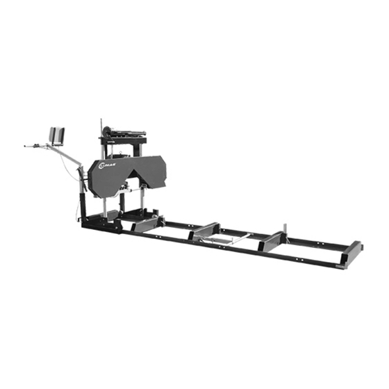
Page 5: Description Of The Sawmill
DESCRIPTION OF THE BAND SAWMILL A. Saw carriage J. T-handle for saw blade tensioning B. Crank for adjusting cut depth K. Fluid reservoir for saw blade cooling C. Adjustable blade guard L. Plug D. Lever & throttle control M. Lifting points on the saw carriage E. -
Page 6: Safety Instructions
SAFETY INSTRUCTIONS Key to symbols Warning! This symbol means that you have to take particular care. It is always accompanied by information on the specific risk. ATTENTION. Pay extra attention when this symbol appears in the text. It will be followed by an admonition or a warning. - Page 7 Always have a complete first aid kid available at the workplace. The machine must be installed with a residual current device. The machine can be only used outdoor. Using the bandsaw mill Warning! Cutting tool: Always stand behind the saw carriage and keep both hands on the handle when operating the machine.
- Page 8 The safe distance on the bandsaw’s left side is 15 m, as there is a risk of saw blade fragments being ejected via the chip ejector in the event of saw blade breakage. The extent of the hazardarea on the other sides is 5 m. Warning! Keep your hands, arms, legs and other parts of your body well away from the bandsaw blade, cables and other moving parts.
-
Page 9: Sawmill Assembly Instructions
after shutdown. This also applies when the engine is idling. Warning! Risk of fire. Petrol and petrol vapours are highly flammable. Remember the fire, explosion and inhalation risks involved. Warning! Fire risk. The engine must have been shut down and allowed to cool for 10 min before fuel is added. Always shut down the combustion engine when you leave the operator station, even if just for a short time, to deal with sawn wood or perform maintenance. - Page 10 #1 – INSPECTION Take all of the parts out of the shipping crate and lay them out. Check for any damage or missing parts. #2 – TRACKS Assemble track system and secure loosely with provided nuts & bolts. It is important not to fully tighten the bolts at this stage.
- Page 11 Assemble log dog pieces as shown below and use waterproof grease on threaded handle and “T” handle. Attach assembly to the track using the provided nuts & bolts and tighten. Clamp for Clamp for small large log logs & cants Attach log dog assembly to track as shown above with the 4 nuts and bolts provided. Note that there are various locations along the track where this assembly can be bolted.
- Page 12 Lay the above carriage pieces out. Assemble round vertical post (shown on left) to wheel assembly using the two bolts and back plate. Repeat same step for the square vertical post assembly (shown on right). Place a moving blanket on the shipping pallet that the sawmill crate was strapped to. The blanket will prevent the blade guard covers from becoming scratched.
- Page 13 Insert the rear square frame into the carriage base until it bottoms out on the pulley bolts. Tighten the four 16mm bolts (shown in right image) to secure it in place. Adjustme nt nut Lock the cam handles on both the round and square post to prevent the head from moving when it is stood up in the coming steps.
- Page 14 Install the nut on the inside of the round post to secure the pulley. Using a 16mm wrench to hold the nut, tighten the bolt. Insert the bolts into the back plate as shown in above left image. Align the square post holes with the corresponding black top cross support holes.
- Page 15 Slide the scale indicator over the square rod and tighten. Install the cables to the pulleys as shown above. Attach the cable bolts to the brackets on the sawmill head as shown above. It is ideal to lower the sawmill head all the way down to the deck.
- Page 16 Using a tape measure, take a measurement from the blade to the top of the log bunk on both the left and right side. The distance should be equal on both sides. If it isn’t, you need to adjust the cable bolts (shown on page 13) up or down to raise or lower the head on one side until themeasurement is consistent on both sides.
- Page 17 Use the tap at the water tank to adjust the liquid flow by turning the screw left and right. Attach the four track sweepers to the frame so that the steel brush reaches the bottom of the groove in the carriage wheels.
- Page 18 Push the saw head up and down the track system to ensure that the width of the track allows for the saw head to move freely. If it binds, the “L” rails will need to be set further or closer together to achieve a consistent width along the entire track system.
-
Page 19: Sawmillset-Upprocedures
SAWMILL SET-UP PROCEDURES #1 – BELT TENSION To check the belt tension, with a tension meter, deflect the belt up and down with 60N force. There should be no more than 5-6mm of deflection in both directions. If the belt deflects more than this, it will need to be tightened as described below. - Page 20 #2 – BLADE TRACKING Never attempt the below with the engine running. As a safety precaution, remove the spark plug cap. It is also advised to wear gloves and safety glasses when working with the blade, as it is extremely sharp. 9.5mm Rearward Direction Forward Direction...
- Page 21 The alignment bolt can now be turned to change the angle of the bandwheel and track the blade. To move the blade more rearward on the bandwheel, this bolt will need to be turned clockwise. Alternatively, turning the bolt in the counter-clockwise direction would force the blade to run more forward on the bandwheel.
- Page 22 #3 – BLADE GUIDE ADJUSTMENT Never attempt the below with the engine running. As a safety precaution, remove the spark plug cap. It is also advised to confirm that the blade is tracking properly before performing the below. Blade tracking is covered in the previous page.
- Page 23 LOAD AND LOCK THE LOG TO THE BED With the help of a cant hook, load the suitable log to the bed of the sawmill. Push the log/cant to the Supports and make sure there is no space left between the log/cant and the Supports. (For supports use, Refer to page 11.) Lock the log/cant with the log dog.
-
Page 24: Blade Slidable Guard Adjustment
BLADE SLIDABLE GUARD ADJUSTMENT slidable blade guard Head-stopper Loose two T bolts on the tube showed above in the red circle, and then slid the blade guard left/right to adjust the blade length for cutting. Put the “Head-stopper” to the correct position as the above picture show. -
Page 25: Cutting Height Adjustment
CUTTING HEIGHT ADJUSTMENT Un-lock Lock Loose two lock handles of the Saw-head. Turning the Crank to adjust the height of the cutting head of the Sawmill to reach suitable height. You can fix the height of the board with the ruler beside of the crank. “After adjusting the cutting height, be sure to lock the two Cam lock handles before start engine.”... -
Page 26: Run Your Sawmill
RUN YOUR SAWMILL Model # PBS26G, start the engine (refer to the engine manual), then push the throttle handle and the guiding-wheel locking handle down completely, and then pushes the cutting head to the log/cant slowly. Model # PBS26E, 1. Connect the electric cable. electric supply tolerances: 400V±5%, 50±1%Hz;... -
Page 27: Sawmill Maintenance
SAWMILL MAINTENANCE #1 – CHANGING THE BLADE Never attempt the below with the engine running. As a safety precaution, remove the spark plug cap. Gloves and safety glasses must be worn when changing the blade. Remove the tension in the blade by turning the “T” handle in the counter-clockwise direction and then open the blade guard cover. - Page 28 To change the drive side belt, loosen the four bolts that secure the engine to the engine mount using a 16mm wrench. Now that the engine is free to slide on the engine mounting plate, turn the 16mm nut on the horizontal stud in the counter-clockwise direction.
- Page 29 Problem/Issue Possible Causes Resolution Options Producing wavy cuts. 1. Inadequate blade tension. 1. Tighten blade. Refer to page 32. 2. Improper blade guide set up. 2. Gap between guide blocks and blade are incorrect. P 31. 3. Improper blade tracking. 3.
- Page 30 Technical Data BSW-66E BSW-GL 1. Max. Log diameter 660 mm 660 mm 2. Max. Opening 580mm 580mm 3. Max. Elevation of blade 500mm 500mm 4. Min. height from beam 35 mm 35 mm 5. Max. Depth of cut 180mm 180mm 6.
- Page 31 Noise declaration PSB26G: L dB(A), L dB(A); PSB26E: L dB(A), L dB(A); Associated uncertainty K = 4 dB Measurement made in accordance with EN ISO 3746:2010. The operating conditions is described in 5.4.2 and Annex B of EN 1807-2. The figures quoted are emission levels and are not necessarily safe working levels. Whilst there is a correlation between the emission and exposure levels, this cannot be used reliably to determine whether or not further precautions are required.
Need help?
Do you have a question about the BSW66GL and is the answer not in the manual?
Questions and answers