Table of Contents
Advertisement
Quick Links
Advertisement
Table of Contents

Summary of Contents for Toa WB-31
- Page 1 INSTALLATION MANUAL FLAT LCD DISPLAY MOUNT MODEL WB-31 Swingout Arm Mount...
- Page 2 Parts List Installation Tools l l a i t a l l a i t a l l a i t a i l l i t s l l a i t a Page 2 TABLE OF CONTENTS Installation Instructions...
-
Page 3: Warning Statements
WARNING: THE WALL STRUCTURE MUST BE CAPABLE OF SUPPORTING AT LEAST A MAXIMUM WEIGHT OF 50 LBS. IF NOT, THE WALL MUST BE REINFORCED. PROPER INSTALLATION PROCEDURE BY A QUALIFIED SERVICE TECHNICIAN, AS OUTLINED IN THE INSTALLATION INSTRUCTIONS, MUST BE ADHERED TO. FAILURE TO DO SO COULD RESULT IN SERIOUS PERSONAL INJURY, OR EVEN DEATH. -
Page 4: Parts List
Parts List NOTE: This mount is shipped with all intallation hardware and components. Make sure that none of these parts are missing and/ or damaged before beginning installation. If there are parts missing and/or damaged, please stop and contact TOA Electronics, Inc. Swingout Arm (Qty 1) 1/4”... -
Page 5: Backplate Installation - Wood Stud
Backplate Installation - Wood Stud NOTE: These installation instructions will apply to the WB-31 Swingout Arm Mount. The following steps will outline how the back plate will be mounted. 1. Determine where the mount location will be. 2. Use a stud finder (sold separately) to locate the nearest wall stud. -
Page 6: Backplate Installation - Concrete Surface
Backplate Installation - Concrete Surface NOTE: These installation instructions will apply to the WB-31 Swingout Arm Mount. The following steps will outline how the back plate will be mounted. 1. Determine where the mount location will be. 2. After this has been determined, line-up the holes of the backplate. -
Page 7: Installation
WARNING: Failure to fully tighten the locking screw may result in possible damage to your display. NOTE: In reference to Figure 5, the dash lines represent the back plate that is mounted to an existing surface. Installation Instructions Figure 5. WB-31 Installation Page 7... -
Page 8: Installing The Monitor
Cable Access Please refer to Figure 7 for the correct way to route existing any cables. WB-31 Articulating Swingout Arm - After the monitor has been mounted, remove the cable access plastic Cable access holes Cable access... -
Page 9: Adjusting The Swingout Arm
NOTE: The tilt/pivot adjustment nut is located on the back of the tilt/pivot mount. Installation Instructions NOTE: The mount shown in this illustration is upside down to access the adjustment nuts. caps Figure 8. Swing Arm Adjustment WB-31 Page 9... -
Page 10: Adapter Plate Installation
Attach the 100x200 Adapter Plate to the back of the display using the provided hardware (see Parts List, page 4). Attach the WB-31 mounting plate to the back of the 100x200 using the M4 x 5 mm screws. 200x200 Aapter Plate Figure 9B: Attach the 200x200 Adapter Plate to the back of the display using the provided hardware (see Parts List, page 4). -
Page 11: Technical Specifications
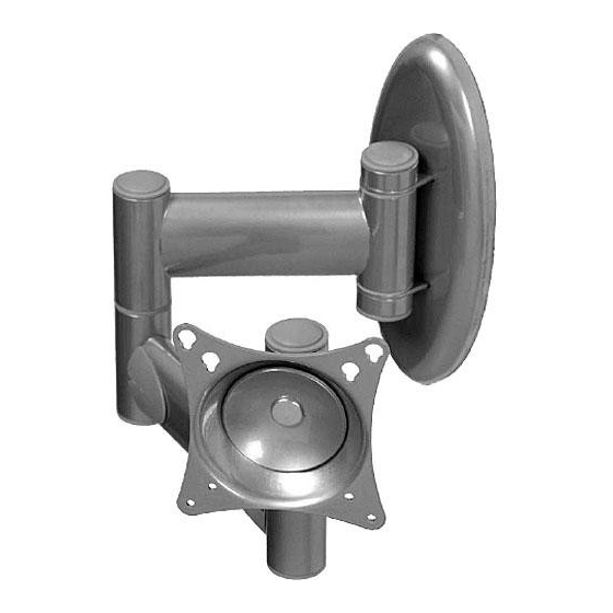
WB-31 Technical Specifications Figure 11. WB-31 Swingout Arm Installation Instructions Page 11... - Page 12 WB-31 E255449 29GZ WALL MOUNT IN-WB31.R2 Mfg. Date Page 12 Installation Instructions...


Need help?
Do you have a question about the WB-31 and is the answer not in the manual?
Questions and answers