Table of Contents
Advertisement
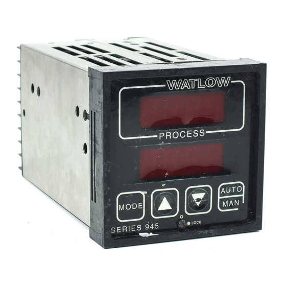
Series 945
User's Manual
TOTAL
CUSTOMER
SATISFACTION
3 Y ear Warranty
1/4 DIN
Microprocessor-Based
Auto-tuning Control
Watlow Controls
1241 Bundy Blvd., P.O. Box 5580, Winona, Minnesota USA 55987-5580, Phone: 507/454-5300, Fax: 507/452-4507
0600-0017-0000 Rev A
$10.00
August, 1994
Made in the U.S.A.
Supersedes without change: W945-MA40-9432
Recycled Paper At Least 10% Postconsumer Waste
Advertisement
Table of Contents

Related Manuals for Watlow 945 Series


Summary of Contents for Watlow 945 Series
- Page 1 CUSTOMER SATISFACTION 3 Y ear Warranty 1/4 DIN Microprocessor-Based Auto-tuning Control Watlow Controls 1241 Bundy Blvd., P.O. Box 5580, Winona, Minnesota USA 55987-5580, Phone: 507/454-5300, Fax: 507/452-4507 0600-0017-0000 Rev A $10.00 August, 1994 Made in the U.S.A. Supersedes without change: W945-MA40-9432...
-
Page 2: Table Of Contents
The CAUTION symbol in the wide text column alerts you to 945 User's Manual and integral software are copyrighted a "CAUTION," a safety or functional hazard which could by Watlow Winona, Inc., © 1989, with all rights reserved. affect your equipment or its performance. A full explana- blr0392 tion is in the narrow column on the outside of the page. -
Page 3: General Description
HYS (hysteresis) parameter in the Setup menu. Operator-friendly features include automatic LED indicators to aid in monitoring and setup, as well as a calibration offset at the front panel. The Watlow Series 945 automatically stores all information in a non-volatile memory. -
Page 4: How To Install And Wire The Series 945
Series 945 Case. 4. Insert the control chassis into its case and press the bezel to seat it. Turn the front panel screw 90° clockwise (CW) to lock the control in place. Install and Wire, Chapter 2 WATLOW Series 945 User's Manual... -
Page 5: Sensor Installation Guidelines
For 0-5VDC or 4-20mA process inputs: The rL and rH settings scale the display to match the measured range of the process signal. For 0-5VDC process input, the impedance is 100KΩ. For 4-20mA process input, the impedance is 249Ω. Install and Wire, Chapter 2 WATLOW Series 945 User's Manual... -
Page 6: Input Wiring
_ _ _ - _ 000 Figure 10 - A jumper must be 4-20mA Process 945A - 3 _ _ _ - _ 000 installed between Input Wiring. Terminal #2 and 3. WATLOW Series 945 User's Manual Install and Wire, Chapter 2... -
Page 7: Output 1 Wiring
Output 1 - Process, 4 - 20mA turned OFF. 945A - _ _ _ - _ 000 Process, 4-20 mA, Non-Isolated Figure 14 - Process, 4-20mA External Load Load impedance: 600Ω max. Install and Wire, Chapter 2 WATLOW Series 945 User's Manual... -
Page 8: Output 2 Wiring
12 to 19 945A - _ _ _ - _ 000 Non-Isolated volts. Logic External Switch Load Figure 18 - Switched DC Output (Open Collector) Load impedance: 10KΩ min. WATLOW Series 945 User's Manual Install and Wire, Chapter 2... - Page 9 Alarm Output - Mechanical Relay, 6 Amp, Dual Form A or B 945A- _ _ _ - _ 000 Fuse Figure 22 - Alarms Suppression Option 2 Wiring. Load Output #4 Fuse Output #3 Load Off state impedance: 20KΩ min. Install and Wire, Chapter 2 WATLOW Series 945 User's Manual...
- Page 10 Load Load impedance: 10KΩ min. 4 - 20mA Retransmit Output 945A- _ _ _ - _ 000 Figure 26 - Retransmit External Option 6 Wiring. Load Load impedance: 600Ω max. WATLOW Series 945 User's Manual Install and Wire, Chapter 2...
- Page 11 Contact your local board for additional information. Failure to observe NEC safety guidelines could result in injury to personnel. ç CAUTION: Watlow mercury relays are designed to be used only with resistive loads. Figure 27 - System Wiring Example...
-
Page 12: How To Use The Keys And Displays
Calibration Menu will appear. the AUTO/MAN key toggles between Auto and Manual. After 5 seconds without press- ing the AUTO/MAN key, the LED stops blinking, and re- turns to its previous state. WATLOW Series 945 User's Manual Keys and Displays, Chapter 3... -
Page 13: How To Setup The Series 945
See Appendix II to change this parameter. How to Set the DIP Switch The Watlow Series 945 has a Dual In-line Package (DIP) switch inside the control on the A007-1954 circuit board (middle board). The location of the board and switches appear below. -
Page 14: Setup Parameters
LOC 3: The set point and actual are the only visible parameters, set point is not adjustable in this level of lockout. Manual operation is not permitted. Bumpless transfer is defeated, outputs are disabled on sensor break. Setup, Chapter 4 WATLOW Series 945 User's Manual... - Page 15 Ot2 = no. Range: 1°F - 99°F 0.1°F - 9.9°F Default: 3°F/0.3°F 1°C - 55°C 0.1°C - 5.5°C 1 Unit - 99 Units 0.1 Units - 9.9 Units WATLOW Series 945 User's Manual Setup, Chapter 4...
- Page 16 JIS = 0.003916Ω/Ω°C, DIN = 0.003850Ω/Ω°C. Range: din or JIS Default: din Any parameters that appear after RTD are related to data communications. See How to Use Data Communications with the Watlow Series 945 for more information. Input Type Sensor Range Low Sensor Range High 32°F/0°C...
- Page 17 0.1°F - 9.9°F, 0.1°C - 5.5°C, 0.1U - 9.9U AL2 = Pr or dE On or OFF Unit has alarms & AL1 = dE JIS or din In = rtd or rt.d WATLOW Series 945 User's Manual Setup, Chapter 4...
-
Page 18: Operation Parameters
If dFL = US: Range: 0 to 999°F/0 to 555°C/0 to 999 Units; 0.0 to 9.9°F/0.0 to 5.5°C/ 0.0 to 9.9 Units Defaults: Pb1 = 25°F/2.5°F Pb2 = 0 If dFL = SI: Range: 0 to 999.9% of span Defaults: Pb1 = 3.0% Pb2 = 0.0% Setup, Chapter 4 WATLOW Series 945 User's Manual... - Page 19 Range: A2LO to rH Default: rH Calibration Offset: Adds or subtracts degrees from the input signal. Range: -180°F to 180°F/-100°C to 100°C/-180Units to 180 Units; or -180.0°F to 180.0°F/-100.0°C to 100.0°C Default: 0 WATLOW Series 945 User's Manual Setup, Chapter 4...
- Page 20 0° to 999° 999° AL2 = Pr, dE Process Pr A2LO to rH Unit has Alarm 2 ±180°F/±100°C/±180U Ot1 = ht, L-r = L L or r rsP = 0-5 or 420 Setup, Chapter 4 WATLOW Series 945 User's Manual...
-
Page 21: How To Tune And Operate
80 minutes after auto-tune has started. If this does not happen within the 80 minute time limit, the Pb remains at 0 and the control functions in an ON/OFF mode. WATLOW Series 945 User's Manual Tuning and Operating, Chapter 5... -
Page 22: Manual Tuning
Experiment until the cycle time is consistent with the quality of control you want. Ct will not appear on units with a process output. Tuning and Operating, Chapter 5 WATLOW Series 945 User's Manual... -
Page 23: Manual And Automatic Operation
("bumpless," smooth transition). When transferring from manual to automatic operation, the control output(s) may change significantly. In manual operation, the output value appears in the lower display; in automatic operation, the set point appears. WATLOW Series 945 User's Manual Tuning and Operating, Chapter 5... -
Page 24: Changing The Position Of An Alarms Jumper
The alarm output de-energizes upon an alarm or power interruption to the 945's power supply. When you select N.O. Contacts, the contact is open when an alarm occurs. When selecting N.C. Contacts, the contact closes when an alarm occurs. Tuning and Operating, Chapter 5 WATLOW Series 945 User's Manual... -
Page 25: Using Alarms
"safe" region of the deviation alarm band. Once the process value crosses into the "safe" region, both a latching or a non- latching alarm is ready. Any future deviation outside this safe band triggers an alarm. WATLOW Series 945 User's Manual Tuning and Operating, Chapter 5... -
Page 26: Error Code Messages
Check the sensor; if the connection is good, and functions properly, call the factory. The A/D overrange voltage is too high to convert an A/D signal. Make sure the In parameter matches your sensor. Tuning and Operating, Chapter 5 WATLOW Series 945 User's Manual... -
Page 27: Error Code Actions
• The above conditions occur regardless of the LOC value, or the presence of the Setup or Calibration Menus. • To clear a corrected error… • Cycle power to the control. WATLOW Series 945 User's Manual Tuning and Operating, Chapter 5... -
Page 28: Appendix 1 28 Noise Sources
◊ Maintain shield continuity at daisy chain connection points by reconnecting the broken shield. ◊ Assume no electrostatic shielding when using the shield as a signal return. If you must, use triaxial cable (electrostatically shielded coaxial cable). Appendix WATLOW Series 945 User's Manual... -
Page 29: Eliminating Noise
0.1µf, 600 volt, non-polarized capacitor in series with a 100 , 1/2 watt resistor. The device can be used on A.C. or D.C. circuits to effectively dampen noise at its source. • The general purpose Watlow snubber, described above, is 0804-0147-0000. For other "QUENCHARC" sizes contact: PAKTRON P.O. -
Page 30: Checking For Ground Loops
"open" you have eliminated the ground loop(s). Also, as you reconnect grounds, keep making the continuity test. It is possible to reconnect a ground loop. Noise Suppression Devices Available From Watlow Watlow Controls stocks a few key noise suppression parts. You may order these by calling your local Watlow distributor. Item... -
Page 31: Line Filtering Configurations For Controls
Doing so will reduce filter effectiveness. Figure 38 - Common Mode Filter Wiring Figure 39 - Combination Load Line Differential/Common Mode Filter Wiring Appendix WATLOW Series 945 User's Manual... -
Page 32: Appendix 2
Press the UP/DOWN keys to change the upper display to “YES.” Press the MODE key to enter the calibration sequence. NOTE: While in the Calibra- tion Menu, all outputs are OFF, except the 4-20mA output. WATLOW Series 945 User's Manual Appendix... -
Page 33: Restoring Factory Calibration
4. Press the UP key until YES appears in the upper display. 5. Press the MODE key and the 945 advances to test the displays. This procedure is used only to restore calibration, it is not meant to clear values. Appendix WATLOW Series 945 User's Manual... - Page 34 (integral, derivative, proportional band in % of span, °C). Factory use only. ç Before attempting to calibrate, make sure you have the proper equipment called for in each procedure. The Series 945 is calibrated and tested before leaving the factory. WATLOW Series 945 User's Manual Appendix...
- Page 35 The unit leaves the CAL mode if 1 minute passes between key activations. Press AUTO/MAN twice to exit the MANUAL mode. To conclude, advance the MODE key to the next prompt or exit the CAL menu. Appendix WATLOW Series 945 User's Manual...
- Page 36 The unit leaves the CAL mode if 1 minute passes between key activations. Press AUTO/MAN twice to exit the MANUAL mode. To conclude, advance the MODE key to the next prompt or exit the CAL menu. WATLOW Series 945 User's Manual Appendix...
- Page 37 ± 20.15mA 0.10mA on 0-20mA units and 4-20mA units. Press the AUTO/MAN key twice to exit the MANUAL mode. To conclude, advance the MODE key to the next prompt or exit the CAL menu. Appendix WATLOW Series 945 User's Manual...
- Page 38 Use the UP/DOWN keys (reverse acting) to adjust the reading on the multimeter for 20.00mA. Press AUTO/MAN twice to exit the MANUAL mode. To conclude, advance the MODE key to the next prompt or exit the CAL menu. WATLOW Series 945 User's Manual Appendix...
- Page 39 Also "rate." JIS Japanese Industrial Standards. Also Japanese Deviation alarm: An alarm referenced at a fixed Industrial Standards Committee (JISC). Establishes number of degrees, plus or minus, from set point. standards on equipment and components. Appendix WATLOW Series 945 User's Manual...
- Page 40 AC process temperature. Also "integral." line. RTD: Resistance Temperature Detector. Resistive sensing device displaying resistance versus tem- perature characteristics. Displays positive tempera- ture coefficient. Appendix WATLOW Series 945 User's Manual...
-
Page 41: Index
Output 1 Wiring, 7 Input Wiring, 6 Output 2 Wiring, 9 Tuning, 21 Alarm Wiring, 9 U, V, W MODE key, 12 UP key, 12 Model Number, 43 Upper Display, 12 Mounting, 4 Warranty, 43 Wiring, 5 Appendix WATLOW Series 945 User's Manual... -
Page 42: Specifications
7.0 in 178 mm load impedance,non-isolated. • Behind panel depth: 6.0 in 153 mm • 0-5 VDC reverse or direct into a 1KΩ minimum load • Weight: 2.5 lb max. 0.4 kg impedance, non-isolated. WATLOW Series 945 User's Manual Appendix... -
Page 43: Returns
Warranty • Symptoms and/or special instructions • Name and phone number of person returning The Watlow Series 945 is warranted to be free of defects the material. in material and workmanship for 36 months after delivery to the first purchaser for use, providing that the units have 2. - Page 44 Watlow Series 945 User's Manual Watlow Controls, 1241 Bundy Blvd., Winona, MN 55987, 507/454-5300, Fax: 507/452-4507 WATLOW Series 945 User's Manual Appendix...
Need help?
Do you have a question about the 945 Series and is the answer not in the manual?
Questions and answers