
Subscribe to Our Youtube Channel
Related Manuals for Watlow QPAC-01


Summary of Contents for Watlow QPAC-01
- Page 1 QPAC User’s Manual Modular SCR Power Control 1241 Bundy Blvd., P.O. Box 5580, Winona, MN 55987-5580, Tel: +1 (507) 454-5300, Fax: +1 (507) 452-4507 http://www.watow.com 0600-0027-0001 Rev C Made in the U.S.A. July 2003 $10.00...
-
Page 2: How To Use The Manual
If the problem persists, you can get technical assistance from your local Watlow representative (see back cover), by e-mailing your questions to wintechsupport@watlow.com or by dialing +1 (507) 494-5656 between 7 a.m. and 5 p.m., Central Standard Time (CST). -
Page 3: Table Of Contents
How To Install And Wire The QPAC - Chapter 2 System Planning Mounting The QPAC Case Style A Mounting: QPAC-01, 30-50A Case Style B Mounting: QPAC-01, 75-100A; QPAC-32, 30-100A 9, 10 Fuse Templates 11, 12 Case Style C Mounting: QPAC-01, 150-300A; QPAC-32, 150-300A;... -
Page 4: Starting Out With The Qpac - Chapter
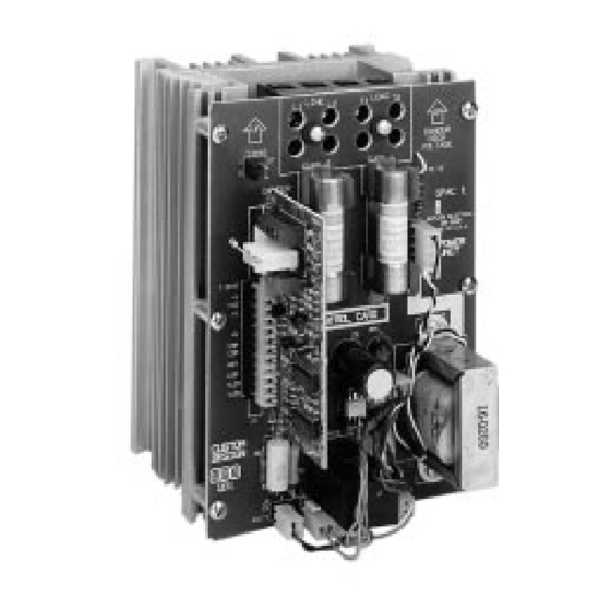
Chapter 1 Starting Out With The QPAC, Modular SCR Power Control Figure 1 - The QPAC-01 SCR Power Control General Description The QPAC Power Controls are a family of solid state controls used for electric heating applications. A solid state power control provides output power that is proportional to the input command signal from a temperature control. -
Page 5: Steps To Put Your Power Control To Work
OEMs to maintain minimum inventories while still providing rapid service. The different QPACs provide the types of power control needed for different power sources and loads. The QPAC-01 is designed for all single phase power sources and loads. The QPAC-32 is for three phase zero cross applica- tions such as resistance heating elements, balanced or unbalanced. - Page 6 System Planning This chapter tells you how to install the QPAC. All mounting and wiring infor- mation is right here. Watlow power controls are thoroughly tested before leaving the factory, so the QPAC is ready to install when you receive it.
- Page 7 QPAC Case Style A Model Amps Height (H) Width Depth Fans Fuses Overall Dimensions (mm) (mm) (mm) QPAC-01 6.5 165 None Two, Onboard QPAC-01 Below 6.5 165 None Two, Onboard Figure 4 - ç QPAC Case Style A Mounting Footprint 5.00 (127mm)
- Page 8 (mm) (mm) (mm) QPAC-32 10.5 8.5 208 Two, External* 5.69 145 QPAC-01 10.5 8.5 208 One, External** 4.90 124 QPAC-01 100 10.5 8.5 208 One, External** 4.90 124 QPAC-32 10.5 8.5 165 Two, External* 5.69 145 QPAC-32 14.5 8.5 229 Two, External** 4.90 124...
- Page 9 Fuse Template Use the next two pages as templates for mounting your fuse holder kit. Choose Starting Out the size that matches your kit and carefully punch out the template along the perforation. ç CAUTION: Spacing for multiple fuses must conform to the National Electric Code (NEC) 5.69...
- Page 10 0.63 Figure 8 - for #10 (16mm) Fuse Holder Kit fasteners Mounting Template for: QPAC-01, 75 & 100A (1 Fuse Kit) QPAC-32, 75 & 100A (2 Fuse Kits) QPAC-33, 75 & 100A Stud Size 5/16" (3 Fuse Kits) Fuse Holder...
- Page 11 13.00 MOUNT (330mm) ∫ 11.75 WARNING: (299mm) Style C heatsinks are electrically HOT. Figure 10 - QPAC Case Style C, QPAC-01, 150, 200, 0.38 (10mm) 300A Single Phase 2 PL Mounting Footprint Install and Wire, Chapter 2 QPAC User's Manual...
- Page 12 Case Style C Starting Out ∫ ç Figure 11 - 14.00 (356mm) QPAC Case Style C, Q32, 3.50 7.00 (178mm) (89mm) 0.63 (16mm) 150, 200, 300A, Three Phase-2 Leg Mounting Footprint MOUNT ç 11.75 (298mm) CAUTION: 13.00 Mount the QPAC (33mm) vertically (height dimension vertical)
- Page 13 Case Style F Starting Out NOTE: See separate Addendum page for Case Style E. Figure 13 - QPAC Case Style F Case Style F Dimensions Model Amps Height Width Depth Fans Fuses Holder (max) Table 5 - in (mm) in (mm) in (mm) (mm) QPAC Case Style F...
-
Page 14: How To Install And Wire The Qpac, Chapter 2
CAUTION: Check terminals for tightness before applying power and then recheck terminals after one day of operation. Loose connections can damage the SCR. ∫ ∫ QPAC-01 Power and Load Wiring WARNING: To avoid potential electric shock and other hazards, all... - Page 15 Wire QPAC-01 ç Starting Out CAUTION: Check terminals for tightness before applying power and then recheck terminals after one day of operation. Loose connections can damage the SCR. Figure 17 - QPAC-01 Wiring for 75-100A Units QPAC-01 75-100A ① ②...
- Page 16 Wire QPAC-32 ç Starting Out CAUTION: Check terminals for tightness before applying power and then recheck terminals after one day of operation. Loose connections can damage the SCR. QPAC-32 Power and Load Wiring Factory supplied, customer installed QPAC-32 30 To 50A external semiconductor fuse Contactors Figure 19 -...
- Page 17 ç Wire QPAC-33 Starting Out CAUTION: Check terminals for tightness before applying power and then recheck terminals after one day of operation. Loose connections can damage the SCR. QPAC-32 150 - 1000A Figure 21 - QPAC-32 Wiring for 150 - 1000A Units ①...
-
Page 18: Input Signal Wiring
Input Wiring Input Signal Wiring Starting Out When wiring the input signal do not run any signal wires alongside or in the same conduit with the A.C. power or load wires. Signal input should be provided by shielded, two conductor wire. Shield should be grounded at the temperature control end only. -
Page 19: Cd Control Card Dc Input
Input Wiring CD Control Card DC Input Starting Out For DC input, the input signal is wired into Pin 2 (+) and Pin 3 (-) of the input signal connector. An input signal of 3-30VDC turns the QPAC power control ON. -
Page 20: Af, Al, Bf And Bv Control Cards
Input Wiring Starting Out Process Input - AF, AL, BF and BV Control Cards The QPAC AF, AL, BF and BV Control Cards are defined as follows: AF - Phase Angle Control AL - Phase Angle Control with Current Limit BF - Burst Firing (Zero Cross), Fixed Time Base BV - Burst Firing (Zero Cross), Variable Time Base All four of these cards can be wired for a manual potentiometer input or an input... -
Page 21: Af, Al, Bf And Bv Auto/Manual Input
Input Wiring AF, AL, BF and BV Auto/Manual Input Starting Out The AF, AL, BF and BV Control Cards can be wired to make it possible to select an input from either a temperature control or a manual input potentiome- ter. - Page 22 Input Wiring AL Control Card Current Transformers, cont'd. Starting Out 20mA TB-3 Figure 29 - Current Transformer AL Card (C.T.) Connections, One C.T. 50 Amps Or TB-2 Load Wire Less, 1Ø Load Figure 30 - Example Current Transformer (C.T.) Connections One C.T., 75 Amps 20mA TB-3...
- Page 23 Input Wiring Single and Three Phase DH Option Starting Out Open Heater or Shorted SCR Detector 120 VAC To Alarm N.C. or Contactor Momentary Reset Switch Figure 32 Customer Supplied Relay Single and Three (Philips ECG PIY 1055 or equivalent) Phase Wiring Open heater Shorted SCR...
-
Page 24: Qpac System Wiring Example
System Wiring QPAC System Wiring Example Starting Out Figure 33 - QPAC System Wiring Example ∫ Line Line Neutral Neutral Fuse ∫ Series Fuse High Limit WARNING: Overtemp. Indicator Neutral Follow National (+) 3 Electric Code Line safety practices Fuse 10 - and other locally applicable codes to... -
Page 25: How To Operate The Qpac - Chapter
Operation Chapter 3 Starting Out How to Operate the QPAC Setup Adjustments After the QPAC is installed and wired it may need a few minor adjustments. The three phase power controls require that proper phase rotation exists. QPACs that use the BF, BV, AF or AL Control Cards may need minor bias and gain calibrations. - Page 26 NOTE: The QBV card does not include a bias adjustment. A bias and gain adjustment card can be added to the QBV card in the field. Order Watlow part number 08-7210. Follow this calibration procedure when using the bias and gain card.
- Page 27 Bias & Gain Starting Out Fixed Bias Gain Connector Figure 36 - BV (Rev. B) Control Card BV Fixed Bias Connector & Gain Adjustment TB-1 08-5342 Bias Gain Current Limit Pot (AL Card only) Figure 37 - 08-5411 AL (Rev. B) Control Card TB-2 AL Bias, Gain, &...
-
Page 28: Phase Rotation Adjustments
Troubleshoot QPAC Troubleshooting A technician can isolate a system problem by first checking if the load is good, and the line voltage and temperature signals are present and correct. If the above is true, then the power control may be the problem. This problem may be with the QPAC's control card, transformer or power base. - Page 29 QPAC Specifications Specifications — (1293) Operation • Modular control base with plug-in card and transformer • Plug-in control cards Solid state contactor, Å(ac) or Î(dc) input Burst fire control, fixed or variable time base Phase angle fire control Phase angle control with soft start and current limiting •...
- Page 30 Specifications Line Voltage/Power • 50/60 Hz Å(ac) line frequency, Q32 and Q33 calibration line frequency dependent • Voltage: ±10%, 120, 208, 240, 277, 380, 415, 480, 575V~(ac) Line Voltage Compensation • 10%∆ in line, 2%∆ in load in the 30% to 70% power region (AF, AL and BV) Power Dissipation (Watts) •...
- Page 31 Model No. Model Number Information — (1294) To order, complete the code number to the right with the information below: QPAC = Modular power controller; phase angle, burst, or solid state contactor with fuse(s) and holder(s) included. Phase Single phase 3-phase, 2 leg (optional 3rd leg fuse kit extra.) 3-phase, 3 leg Operating and Output Voltage...
-
Page 32: Accessories
Accessories Accessories 08-5362 = Manual Control Kit * 16-0246 = 20mA Current Transformer * 16-0246 = 30mA Current Transformer * 16-0246 = 40mA Current Transformer * 16-0246 = 50mA Current Transformer 16-0071 = Current Transformer 16-0042 = Current Transformer ** 16-0008 = Current Transformer 16-0044 = 100A Current Transformer... - Page 33 The QPAC is warranted to be free of defects in material and workmanship for 36 months after delivery to the first purchaser for use, providing that the units have not been misapplied. Since Watlow has no control over their use, and sometimes misuse, we cannot guarantee against failure. Watlow's obligations...
-
Page 34: Index
Potentiometer Input, 20 Potentiometer Input, 20 Power And Load Wiring, 14-17 Bias and Gain Adjustments, 25, 26 Burst Firing SCR Control, 5, 20, 29 QPAC-01 BV Control Card Mounting, 6-12 Auto/Manual Input, 21 Power And Load Wiring, 14-15 dc Input, 20... - Page 35 Watlow QPAC Modular SCR Power Control User's Manual Watlow Controls, 1241 Bundy Blvd., P.O. 5580, Winona, MN 55987-5580 Phone: 507-454-5300 Fax: 507-452-4507 QPAC User's Manual Appendix...
Need help?
Do you have a question about the QPAC-01 and is the answer not in the manual?
Questions and answers