Table of Contents
Advertisement
Quick Links
Advertisement
Table of Contents

Related Manuals for Merging Anubis Series


Summary of Contents for Merging Anubis Series
- Page 1 USER MANUAL V21.07.2020...
-
Page 3: Table Of Contents
Contents Thank you for purchasing MERGING+ANUBIS ................... 6 Important Safety and Installation Instructions ................... 7 Product Regulatory Compliance ........................9 MERGING+ANUBIS Warranty Information....................11 INTRODUCTION .............................. 12 Package Content ............................12 OVERVIEW ..............................13 MERGING+ANUBIS VARIANTS AND KEY FEATURES ................ 13 ABOUT RAVENNA ............................ - Page 4 ANUBIS PREMIUM DXD-DSD GUIDELINES ....................97 DSD Features & Restrictions: ........................97 DSD MONITORING: ............................ 98 DSD PreAmps ............................101 ANUBIS SPS ..............................103 ANUBIS USE CASES (MULTIPLE CASES ARE ONLINE) https://confluence.merging.com/pages/viewpage.action?pageId=60031175 ......104 BASIC MONITORING SETUP ......................... 104 RECORDING SETUP ..........................108...
- Page 5 MORE ANUBIS USE CASES HERE https://confluence.merging.com/pages/viewpage.action?pageId=60031175 ......113 MONITORING WEB USER INTERFACE ....................114 How to Open the Remote Web User Interface ................... 115 Web Access Source and Monitor Renaming ..................117 Web Access PreAmps Remote Control ....................118 Web Access Settings ..........................121 Tablets Remote Access - Using the Anubis IP Address ..............
-
Page 6: Thank You For Purchasing Merging+Anubis
Thank you for purchasing MERGING+ANUBIS This manual is intended to take you through the setup and installation of the MERGING+ANUBIS. We encourage you to familiarize yourself with the features, applications, and connection procedures before setting up your MERGING+ANUBIS. To ensure the safe operation of your Anubis please read the instructions, important safety... -
Page 7: Important Safety And Installation Instructions
Important Safety and Installation Instructions INSTRUCTIONS PERTAINING TO RISK OF FIRE, ELECTRIC SHOCK, OR INJURY TO PERSONS WARNING – when using electrical products, basic precautions should be followed, including the following: 1. Before using this product, read all of the safety and installation instructions and the explanation of graphic symbols. 2. - Page 8 Merging Technologies hardware and or software or for any defect in the hardware software or documentation.
-
Page 9: Product Regulatory Compliance
Product Regulatory Compliance Product Safety and EMC Compliance Merging Technologies ANUBIS is designed, tested and verified to comply with the following Safety & EMC regulations FCC – Radiated and Conducted Emissions (USA). CFR 47 Part 15 – Radiated and Conducted Emissions (Canada). - Page 10 Declaration of Conformity According to EMC Directive 2004/108/EC Product Anubis Manufacturer Merging Technologies SA Le Verney 4 CH-1070 Puidoux Switzerland Electrical Rating 90-260 VAC, 50/60 Hz, 0.15 A (at 230V) Standards EN 55103-1:2009, EN 55103-2:2009, EN 61000-3-2 :2006+A1+A2, EN 61000-3-3 :2008...
-
Page 11: Merging+Anubis Warranty Information
Merging Technologies, Inc. extends this Limited Warranty to the original purchaser. In the event of a defect or failure to confirm to this Limited warranty, Merging Technologies, Inc. will repair or replace the product without charge within sixty (60) days. In order to make a claim under this limited warranty, the purchaser must notify Merging Technologies, Inc. -
Page 12: Introduction
Package Content If the shipping carton shows any signs of damage, please inform your Merging Technologies dealer or purchased store, as the product may also have sustained damage. Please retain all the packing, and particularly the soft-shell case, as this must be used should you need to ship the unit in the future. -
Page 13: Overview
Merging Technologies in analogue and digital, networked audio and DSP technology. More significantly, it offers unique features to any engineer or musician looking for a compact AD/DA unit with the quality you would expect from Merging, and a fully featured monitor controller that integrates with any DAW. - Page 14 Two exceptional high-power headphone amps with dedicated DACs ▪ Mute switch for any outputs ▪ The remote allows control of volume level and source selection of any Merging RAVENNA ▪ Device on the network In the Box and Expandable I/O through Hapi, Horus or any RAVENNA/AES67 devices ▪...
- Page 15 Up to 128 Sources capable of up to 22.2 (maximum 128 channels -2 dedicated to ▪ Talkback) Up to 256 channels Analogue, MADI, AES3, SPDIF, Pro Tools HD I/Os via ▪ RAVENNA/AES67 In-the-box I/O pairing management with Merging devices ▪ Any other RAVENNA/AES67 devices pairing using ANEMAN ▪ Adjustable Max, Ref, Dim levels ▪...
-
Page 16: About Ravenna
The RAVENNA protocol comes with standard drivers for all mainstream computer operating systems. ASIO for Windows, Core Audio with DoP support for MacOS and ALSA for Linux. The MERGING+ANUBIS RAVENNA drivers allows use of any application of your choice to record, edit, playback and monitor your music. -
Page 17: Merging+Anubis Panels Description
MERGING+ANUBIS panels description PANEL 1. TFT LCD: High resolution capacitive multi-touch display 2. Home button: Access to Anubis display Main menu cycling and Home page / Settings access 1. Built-in talkback microphone: Mono omnidirectional condenser capsule, located beneath the hole Warning: Avoid touching the built-in microphone, or apply pressure while engaged. - Page 18 5. Headphones # 1 selector: Control over the Headphones 1 output Volume. When engaged and lit, use the main Rotary for local Headphone 1 volume control. The volume control can as well be adjusted remotely (from web access). The button selector can also control different monitor sets, that can be configured from the Anubis Settings.
-
Page 19: Back Panel
BACK PANEL Anubis SPS version 1. Power switch: Sets the power of the device to On (pressed) or Off (released). 2. Kensington Security Slot: Lock mechanisms for protection measure. Metal anchor not provided 3. Power Supply: DC Power Supply connector with lock, to prevent accidental disconnection. The DC power input accepts a voltage from 9V to 15V, with a maximum power consumption of 18W. - Page 20 Warning: Do not exceed the maximum DC input voltage or the unit may be damaged. 4. RAVENNA/AES67 interface: RJ45 female receptacle with a locking EtherCon connector. A network interface adaptor might be required to connect to a USB-A, B, C or Thunderbolt port. The Anubis can be powered via PoE over this port.
-
Page 21: Front Panel
FRONT PANEL 1. Headphones #1: Independent headphones socket with Stereo jack ¼” connector Warning: Depending of the impedance of your headphone set, it is important to make sure that the Headphones output level is set accordingly. For further details refer to the Anubis Settings>IO>Outputs Headphones description 2. -
Page 22: Anubis Analogue I/Oblock Diagram
ANUBIS ANALOGUE I/O BLOCK DIAGRAM... -
Page 23: How To Connect Merging+Anubis
Cat5e, Cat6 or higher cable can be used. Anubis is supplied with a 3 meters Ethernet Cat6 cable, if a longer cable is required, it can be ordered from your Merging Technologies dealer. If using an EtherCon align this one to the Network connector so that the small slot in the EtherCon connector body is facing upwards, then push the connector home until the lock clicks. -
Page 24: How To Connect A Balanced Line Output To An Unbalanced Input
Hi or Lo shorted to ground as would be the case when connecting to an unbalanced input. To connect the MERGING+ANUBIS to an unbalanced input using the balanced outputs, it is recommended to do so as shown in Figure below. -
Page 25: Drivers Installation Procedure
Pyramix MassCore users should only install ANEMAN. 3. After the computer reboot at the end of the installation, open the Merging RAVENNA ASIO Panel and make sure that under "Local Adapter" the Ethernet Interface to which the Anubis is connected to is selected. -
Page 26: Mac Os - Vad Premium
You may configure those later. 5. Make sure that your DAW is started and configured to use the Merging RAVENNA ASIO Driver. MassCore users should launch their VS3 Control Panel and have RAVENNA activated. 6. Launch ANEMAN to connect the inputs and outputs of your choice between the Anubis and the RAVENNA ASIO driver (or MassCore). - Page 27 "System extension blocked" message, go in the Security preferences to unlock the driver. Follow this page for more details. 3. After the computer reboot at the end of the installation, launch the Merging RAVENNA/AES67 Panel from the System Preferences menu. Follow the Virtual Audio Device guide for more details.
-
Page 28: Linux Os - Alsa Driver
1. Connect the Ethernet cable from the Anubis RJ-45 RAVENNA/AES67 port to the Ethernet network port (1Gb) of your computer. 2. Download and Install the Merging LINUX RAVENNA/AES67 Driver. 3. ANEMAN not being supported under Linux, RAVENNA/AES67 connections have to be made from the Advanced Settings RAVENNA pages. -
Page 29: Power Supply
Check that the power cable has the correct plug for the power outlet to which it will be connected. If the wrong Mains cable has been supplied, do not attempt to modify it but contact your Merging Technologies dealer for a replacement. -
Page 30: Switching On Merging+Anubis
Switching ON MERGING+ANUBIS Press the switch on the unit’s rear panel next to the DC input, as shown on the Back-Panel figure. Pressed = ON Released = OFF The Anubis Soft buttons will light up orange when the unit initiates the boot-up sequence, the TFT display will follow soon after. -
Page 31: Touchscreen And Navigation
TOUCHSCREEN AND NAVIGATION Use the following motions and gestures on your touchscreen to navigate the device. Swipe from Right to Left on the TFT screen to view the following menus and pages. Swipe from Left to Right on the TFT screen allows you to return to the previous pages Swipe Up or Down to scroll through menus or various options Single tap on the Anubis TFT to select or enable a function/option... -
Page 32: Anubis Home Page
ANUBIS HOME PAGE As of the Anubis Firmware 1.1.x we include the Mission Hosting icon. Enter the Missions page to load the Mission you plan to use. For the moment only the Monitoring Mission is available. -
Page 33: Status Bar
STATUS Displays information and notifications about the Anubis status 48V: Will light up red if 48 Phantom power is active on an input channel CLP: Clipping peak detected, clear the clipping by either tapping the meters section (PreAmps & Meters page) or use the Peak clear option available in the Meters page (PK) or in the Monitor Control section (refer to the Monitor Mission chapter) OV: Overload detected in the Anubis built-In Mixer. -
Page 34: Logs Messages
LOGS MESSAGES Important events, warnings and errors that occur during Anubis operations are keep the Logs page, which can be accessed from the Anubis Home page. The reported messages in the logs page are intended at first to assist the user in case of operation issues. Refer to the Anubis Log Message Appendix at the end of the Manual for complete listing. -
Page 35: Log Message Appendix
An unexpected behavior has occurred. Proper operation of the software cannot be guaranteed. -2100 Warning Please contact the Merging support by providing the Debug Report. Bass management filter slope X dB/oct can't be recalled, to prevent an inaccurate result a 12dB/oct -2800 Warning slope is applied instead. -
Page 36: Preamps Control
PREAMPS CONTROL Selecting the Preamps icon will open the Anubis Inputs pages. The Preamps Information bar on top of the controls displays: The Input Channel identification, the page position and the name of the Output Monitor set selected. Note: More than three Preamps pages will be available if the Split Channels are enabled under Settings>Inputs>Split. - Page 37 permanently the protective resistors in the input of the Preamp circuitry. If an AD module input circuitry is damaged, following such a short, it will end up permanently having inaccurate gain levels, distortion or even no signal at all on some channels.
- Page 38 Link: Tap to link a pair of input Preamps and control their settings simultaneously. Changes will then be applied to both channels while keeping any Gain value offset (if present). None: Max Mic input level +12dBu for 0dbFS (when Gain set to 0) Pad: Attenuates (lowers) the mic input signal level by 12 dB >...
- Page 39 Peaks: The top Red led of the Preamp metering will indicate that a Peak has occurred. In order to clear the Peak display, simply tap on the meters VU to clear the Peak. Output: The Output meters located on the far right of the UI display the Output level and metering of the selected Monitor whether it is a local Monitor (Main, Line, Headphones 1, Headphones 2) or an over the network Monitor set.
- Page 40 Input 5 Built-in Talkback: Swipe from Right to Left on the TFT screen again to view the Anubis Input 5 that is dedicated to the built-in Talkback microphone. The Preamps controls for the Input 5 will control the built-in Talkback microphone. Notes: The Input 5 Built-in Talkback is shared with Input 4.
-
Page 41: Dual Gain 32Bit Circuitry
DUAL GAIN 32bit CIRCUITRY While based on the extensive experience of Merging’s Horus and Hapi Preamp and AD converter design, the Anubis engineered Dual Gain 32bit A/D circuitry takes Analog/Digital Conversion design one step further. While using 2 A/D converter channels per input as, in the Horus & Hapi... -
Page 42: Split Channel
SPLIT CHANNEL As seen on the right side of the above block diagram, the Anubis AD front-end topology gives also additional flexibility by offering a split channel functionality, where every input channel has a separate split gain control for sending them to different paths. Use Case examples: Typically, an AD could be used for the recording device and have its split channel used for ▪... -
Page 43: Anubis Virtual Keyboard
ANUBIS VIRTUAL KEYBOARD As of Firmware 1.1.8 and above the Anubis includes a Virtual keyboard. You can use the onscreen keyboard to add and edit text. The Anubis keyboard is only available for the moment with a Qwerty US layout. The Anubis Virtual Keyboard is available to edit. - Page 44 Virtual Keyboard - Key Functions. Select a word: Double-tap the word with one finger. Select a sentence: Tap and drag your finger up to desired selection range Use the Virtual Keyboard key to enter the new desired name or entry. OK: Tap the OK key to confirm the new edited text entry, this will automatically close the Virtual Keyboard and Cancel: Tap key to cancel the Edited text and close the Virtual keyboard.
-
Page 45: Settings
SETTINGS The Anubis Settings are accessible from the Anubis home page, by giving a long press on the Anubis Home button. This will open the Settings page scroll up or down to view and navigate through the settings entrie... -
Page 46: Settings Categories Description
SETTINGS CATEGORIES DESCRIPTION GENERAL SETTINGS Sample Rate Sampling Rate Selector to the different sampling rates, available from a drop down menu. Anubis Pro: 44.1kHz, 48kHz, 88.2kHz, 96kHz, 176.4kHz, 192kHz Anubis Premium: 44.1kHz, 48kHz, 88.2kHz, 96kHz, 176.4kHz, 192kHz, 352.8kHz (DXD), 384kHz, DSD64, DSD128, DSD256 DSD Requires the Anubis firmware v1.0.16 and higher. - Page 47 If multiple AoIP devices are used in a network environment, Anubis will try to be elected as the PTP Master priority when enabling this setting, using the Best Master Clock Algorithm (BMCA): Note: Non-Merging devices might not consider Anubis as the PTP Master PTP Status Information on the Anubis PTP status.
- Page 48 Buttons Intensity Adjust brightness of the Anubis physical buttons by using the Anubis Rotary Knob to increase or decrease the intensity. Cooling Mode: Settings are available for either Low, Mid or High Cooling. This affects the threshold at which the fan will start to operate, with reference to the temperature measured internally.
- Page 49 (address range 169.254.x.x if no DHCP server is present) Note: By default the Anubis IP setting is set to “Auto” configuration mode For details on the Anubis SPS model refer to the SPS Manual section here. IP address Set the IP Address for the Anubis unit by using box selection and changing the value using the Anubis rotary knob.
- Page 50 Set the date 24-Hours format by tapping each field (Hours: Minutes: Seconds) one by one and using the Anubis Rotary Knob to adjust. Note: The Date and Time changes will be saved once you exit the Anubis Settings or if you Save the current configuration from Settings>Exit>Save METERS Settings Hot (PCM)
-
Page 51: Presets Settings
until it is exceeded by an even higher peak. This is very useful, as it gives clear indications of where and how hot peaks are, but still allows monitoring of the current signal level. PRESETS Settings Preset Configuration Name. Identify your current configuration. Full configuration save and recall for instant switching between various projects or configurations. -
Page 52: Monitoring Settings
Warning: A Reboot to Factory will reboot the Anubis to the default factory settings, the current configuration will be lost, but all the saved Presets will be kept and can be reloaded. MONITORING Settings The Monitoring settings are the central part of the Monitoring Mission, this is where you can configure the incoming Sources and outgoing Monitor sets and configure their routing. - Page 53 Two different types of Sources can be created Create New Source Standard Sources: for example, for a DAW playback, External Multichannel device, Physical Inputs Create New Stream Listener To Monitor the streams available over a RAVENNA/AES67 network, streams have to be compliant with RAVENNA or AES67, once available Anubis will see those and allow the users to select them for monitoring purpose.
- Page 54 Note: As of the Anubis firmware 1.0.13 and higher, users are no longer restricted to the predefined name listing and can rename their Sources and Monitors with the Anubis Virtual Keyboard or from the Web Access page. Refer to the Virtual Keyboard here or Web Access chapter for more details here.
- Page 55 MONITORS Configure your Monitoring sets, whether you plan to use the Anubis hardware output sets for your Studio Monitor Speaker, Headphones, Cue Mix or to Remotely control the outputs of an external compatible device RAVENNA/AES67 (e.g. Horus or Hapi). Monitor entry page details Note: Use the arrow up or down to move a Monitor to a new ordering position.
- Page 56 Name Name the Monitor by taping the Blue text entry to open the Virtual Keyboard (available as of Firmware 1.1.8 and above). Note: As of the Anubis firmware 1.1.8 and higher, users are no longer restricted to the predefined name listing and can rename their Sources and Monitors with the Anubis Virtual Keyboard or from the Web Access page.
- Page 57 Note: When enabling Mon to Cue only the Sources selection will override the Cue Monitor. The Speaker Set controls: Mute, Solo, Solox, Polarity, Downmix, Ref and Dim will not be injected in the Cue. Trim Trim the level of a Monitor set, apply by turning the Anubis Rotary Knob. Range: -12dB to 12dB (as of Firmware 1.1.x) An individual Channel Trim is available for each channel (refer to the Channel description below) Note: The Trim can also be set directly from the Meters page.
- Page 58 Type: The channel type is predefined in accordance with the selected Monitor Type Patch: Configure the Monitor routing. Users can patch an Anubis Hardware Output Monitor, an external source (e.g. Paired device) or RAVENNA/AES67 Stream. The Patch list starts with the Anubis Hardware inputs followed by the RAVENNA/AES67 Stream, the latter cannot be created from the Anubis.
-
Page 59: Anubis Eq Guidelines
ANUBIS EQ GUIDELINES Important: The Monitor EQ are supported as of Anubis Firmware 1.1.8 and higher. New Anubis EQ for Monitors The Anubis EQ is built on the existing and universally acclaimed quality of the Pyramix EQ-X and offers Extreme definition filtering at sampling frequencies up to DXD. This new EQ support for Monitors is a twelve band fully parametric EQ with independent control of filter type, gain boost and cut, frequency, and Q factor (bandwidth) for each band. - Page 60 SIGNAL FLOW ANUBIS EQ FEATURES EQ available in the Monitors for all Anubis users • EQ Supported from 44.1khz up to 352.8kHz (DXD) and 384kHz • Up to 12 bands per channel with a total limit of 56 bands. • By Example a 12.1 Speakers sets could host 4 EQ Bands per channels.
- Page 61 ANUBIS EQ GENERAL SETTINGS ACCESS The EQ is available from the Settings under Monitors>Channels Press the EQ button in order to access the EQ UI. Bands Activation Tap the EQ UI in order to activate the first 1-4 EQ bands. Note: Graphic Display does not allow dragging EQ bands but only their selection, use button controls in order to apply the frequency parameters.
- Page 62 ANUBIS EQ PARAMETERS CONTROLS Operation: Selected parameter to operate changes and use the Anubis Rotary to apply those. EQ Band selection: Tap the frequency band on the UI itself that you want to configure once a frequency band is selected you can swipe to left or right on the Parameters control to access the adjacent band.
- Page 63 Band Frequency (up to 12) Adjusts the center frequency for the band. Unit: Hz and kHz Value Range: 20Hz / 20kHz Default Value for first five bands: 31Hz / 125Hz / 500Hz / 2kHz / 8kHz Step: 24 steps per octave Gain This knob sets the gain in dB of the selected bands between -24 dB and +24 dB.
- Page 64 Monitor Trim Level Fader and Meters At the far left of the Anubis EQ a Fader is available to control the Monitor Trim level of the selected channel. This once can be operated by using the Gain encoder when no EQ back is selected and that this one is Gray.
- Page 65 EQ Settings menu access Add bands 5-8: Selecting this entry will add Delete current Bands 1-4: Select and confirm to delete the current bands 1-4. Flat: Reset the bands set the bands to peak mode and gain set to 0dB Copy: Copy the current EQ bands parameter, copy can be used to eventually duplicated the EQ parameters for a second EQ Monitor Channel where the Paste dans be used in order to start form the same EQ setting.
-
Page 66: Bass Management
BASS MANAGEMENT Bass Management is available for Speaker Set Monitor sets with at least one LFE channel type. Based on the ZMAN Anubis board that offers built-in high-quality filters directly processed into the FPGA. Those will apply a crossover frequency from all channels (except LFE and LF2) and route low frequency information to the LFE channel(s). -
Page 67: Bass Management Signal Flow
Bass Management Signal flow... - Page 68 Crossfeed Crossfeed only applies to Headphones. It is the process of blending the left and right channels of a stereo audio recording. It is generally used to reduce the extreme channel separation when monitoring with headphones vs. speakers (e.g., where instruments are panned entirely on one side or the other).
- Page 69 Max Level: Set the Maximum volume level boundary, use the Anubis Rotary Knob to set the value. Range: -36dB to +12dB Ref Level: Determine the Reference listening level you wish to establish when recalled. Set the level by using the Rotary Knob. Range: -36dB to +12dB Dim Level: Set the desired Dim level value by using the Rotary Knob.
- Page 70 The TALKS settings have similarities to the Sources settings. Enable: Enable or disable the Talk sources Name: Select the Talk name from the pre-defined naming listing Trim: Apply a trim value to the Talk source Patch: Patch the Talk source, you can choose the local Built-in Mic, any Anubis input where you would connect a Microphone or an AoIP Stream that could be a Microphone connected to another RAVENNA/AES67 compliant device.
- Page 71 When enabled, within the Anubis Preamps pages a second pair of Preamps will appear for each Split Channel pair. Allowing you Split control over: Gain, Polarity and Low Cut parameters. OUTPUTS Settings Global Outputs Setting Roll Off Filter: Sharp: Offers a flat frequency response with an attenuation of 3 dB at 0.484 x FS (23.2 kHz @48k), which has the tradeoff of 35 samples latency.
- Page 72 Slow (default): Offers the lowest latency of 9 samples, with the tradeoff of a gentle frequency response attenuation reaching -3dB at 0.45 x FS (21.6 kHz @48k) Apodizing: Fast Roll-Off filter, Linear phase filter. Latency of 35 samples Brickwall: Ensures rejection of more than -100dB at Nyquist (0.50 x FS, 24 kHz @48k). Latency of 35 samples XLR 1/2: Line output level of the physical XLR outputs 1 and 2 located at the back to the Anubis Max Output Level: +18dBu or +24dBu...
- Page 73 JACK 3/4: Physical TRS jack outputs 3 and 4 located at the back to the Anubis Same parameters as above (XLR 1-2) HEADPHONE 1: Headphone set 1 located at the front Anubis left side Max Output Level: +9dBu or +18dBu Attenuation*: +0dBu or -36dBu Channel 1: Polarity setting Channel 2: Polarity setting...
- Page 74 TRIGGERS Settings MIDI or GPIO Selector: Switch between GPIO or MIDI (default) Users can select either MIDI or GPIO and cannot combine one with the other. Talkback button type: Configure the behavior of the Anubis Talkback button No Latch: Keep pressed to Talk and release to end the discussion Latch: Press to Talk and press again to end the discussion Auto-Latch (default): Auto-Latch (default): Act as No Latch if keep pressed after 333 ms otherwise act as a Latch.
- Page 75 would be reflected (GPO). Enabled the GPIO mode in order to use those I/O (located at the back of the Anubis), by doing so two new entries, GPI and GPO will appear in the Triggers Settings. GPI: and the GPO: General-purpose Input General-purpose Output Settings...
- Page 76 Group: A fixed list of Group options are available Component: Will vary with the Group option selected. Function: Will vary with the Component option selected. Action: Toggle: Action will toggle between ON and OFF On: Action will be turned ON (only) Off: Action will be turned OFF (only) Trig: Applies the action at every triggering Note: In the example here above a footswitch will trigger the PreAmps Cut option On/Off in order to use...
- Page 77 GPI: State/Pulse table Group Component Function Action Description General On/Off/Toggle Mon>Cue On/Off/Toggle Peak reset Do not work if Monitor is a Speaket Set. Use Monitor <Monitor name> Mute On/Off/Toggle Speaker set instead <Monitor name> Downmix On/Off/Toggle SpeakerSet Mute On/Off/Toggle On/Off/Toggle Limitation: Multiple subsequent select on a given Select <Monitor name>...
- Page 78 Created actions are by default enabled, but users can disable an Action at any time Select to delete an action Group: A fixed list of Group options are available Component: Will vary with the Group option selected. Function: Will vary with the Component option selected. Action: No action parameter GPO: On/Off table...
- Page 79 Pedal switch types that can be used for GPIO Momentary switch: Remains in its “on” state only as long as it is being compressed. Once the user removes the compression of the switch the device is no longer on. An everyday example of a momentary switch is an electric drill.
-
Page 80: Info Settings
Loopback: Internal module with Generator (Supporting 1FS) and transparency check tool (Supported up to 384kHz). Under Development. Enabling the Loopback will provide access to the Loopback module within the Anubis I/O’s. Note: The Loopback is for the moment only available as a debugging tool for the Merging Team. -
Page 81: Exit Settings
EXIT Settings Reboot Reboot the Anubis Note: To turn OFF Anubis, press on the POWER button to switch it to the released state. Save Save the current Anubis configuration Note: The Anubis entire configuration is saved every 2 minutes, and as well every time you exit the Anubis Settings. -
Page 82: Anubis Monitor Mission Control
ANUBIS MONITOR MISSION CONTROL The Monitor Mission is designed for professional applications where superior monitoring capabilities are truly mission critical. No matter how large your studio is, monitoring matters. State of the art features that are the standard of today have been carefully integrated, while unique and future proof capabilities were specifically added to the feature set to meet the challenges of tomorrow. - Page 83 Monitor Mission Engine Bypassing the Anubis Monitoring Engine will prevent control over Volume (Rotary), Trim, Mute and more. Such connection could be desired for direct IO use and for connecting for example, an A/D directly to a D/A for Effect Inserts usage. For Monitoring Control purposes this is it not recommended.
-
Page 84: Sources Vs. Monitors Fundamentals
Sources vs. Monitors Fundamentals It is fundamental with the Anubis Monitoring Mission to understand the importance of using Sources (Mixer inputs) and Monitors (Mixer outputs), as this is the base of the Anubis Monitoring Engine. Not doing so will bypass the Monitoring engine and prevent proper Monitor Control (Volume control, Mute, Trim...). -
Page 85: Different Monitor Types
Different Monitor types The Anubis Monitor Mission provides the operator with control over three types of Monitors. Anubis can host up to 8 Monitors, capable of up to 22.2 (maximum 32 channels). 1. Speaker Set Recommended to be used for Speaker Sets (e.g. Reference Monitors). 2. - Page 86 MAIN PAGES - MONITOR MISSION The Monitor mission has 3 main pages, press the Anubis home button to cycle between those. Monitor Page Source page Meters page Single tap on the Anubis Home button to cycle between the three MONITOR Pages. At all times return to the Anubis Home page (Settings/Preamps) by a long press on the Anubis Home button.
-
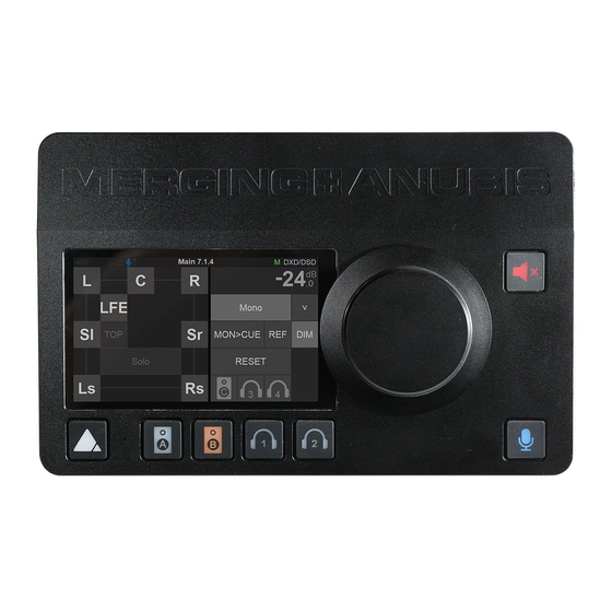
Page 87: Monitor Page
MONITOR PAGE The monitor page is the mother of the Monitoring pages, allowing you to select the fundamental functions of your monitoring setup. A Monitor set will only appear once created in the Anubis Settings, properly configured and assigned to a specific button (hardware key or softkey). Refer to the Settings Sources and Monitors section for all details. - Page 88 Tap the Speaker control box to open the dialog, for Speaker controls such as: Mute, Solo, SoloX and Phase option controls. Those functions can be applied to the Speaker(s) of your choice. Mute: Mute function available for each speaker in your set. Tap a speaker to cut its signal. Figure 10 Example: Muting LFE Solo: Solos the Speaker by muting all other speakers.
- Page 89 Polarity: Invert the polarity of a chosen speaker in your set up. Tap a speaker to invert its polarity, this can be useful to check or fix phase cancellation problems. The polarity is a latching function that can be applied in addition to Mute/Solo or SoloX options. Figure 13 Example: Polarity applied to L and R speaker channels Clear: Use the Clear function to re-initialize the Speaker controls, this will remove all applied controls to the speakers.
- Page 90 Mon > Cue Allows the operator to override the Cue Mix by sending the Speaker Set directly to the Cue listener. Only Speaker Set Monitor types can override cues. To prevent a Cue monitor set from being overridden, enable the inactive option under Settings>Monitors of the selected Cue. Select to recall your reference level, the default Reference level is set to -20 dB and can be configured from the Anubis Settings>Monitor Levels.
-
Page 91: Downmix Table
Downmix Table Monitor Channels - Types vs. Downmix formats available. - Page 92 SOURCE PAGE The Source page allows the operator to select the different Sources he wishes to monitor. You can exclusively select a Source or sum multiple Sources and as well apply level Trim. The Sources page also gives you Monitor Controls, with similarities to the Monitor page. Source Type This first section on the left indicates the Source Type name as well as the Metering of the Source, once this one has been configured and patched form the Settings>Sources.
- Page 93 Note: AoIP Streams up to 8 channels with 7.1 ITU-I default channel type and All Center CCCCCCCC and LRLRLRLRLR types are supported. AoIP streams icons status AoIP disconnected AoIP partially connected AoIP connection error AoIP RTP Error AoIP receiving Source Name/Selector Name of the Source and selector.
- Page 94 Monitors Controls Sum: Enable the Sum option to select multiples Sources and sum them together into your Monitor set. When disabled the Source section is exclusive. Peak Tapping the Peak Reset (PK) will reset the Meters Peaks Mon > Cue Allows the operator to override the Cue Mix by sending the Monitor Set directly to the Cue listener.
-
Page 95: Meters Page
METERS PAGE The Meters page provides an overview of the Sources and Monitors metering, along with some controls over the Sources and Monitors. Sources Meters Metering overview of all the Sources, each source with full details of peak-meters and type per channel. - Page 96 Enable the Sum option to select and sum multiple Sources. When disabled the source section will be exclusive. Tapping the Peak Reset (PK) will reset the Meters Peaks. By default, the Peak hold is enabled. Permanent Peak hold can be disabled under the Anubis>Settings>Meters page. Trim Trim the level of a Source or Monitor by first selecting it, while holding the meter region pressed, adjust the trim by turning the Anubis Rotary knob.
-
Page 97: Anubis Premium Dxd-Dsd Guidelines
In DSD the file is retained in the original DSD format and directly converted to analogue without any unnecessary digital processing or decimation. MERGING+ANUBIS brings its auditors the fidelity of an extremely pure natural sound. SIGNAL FLOW DSD (DSD64, DSD128, DSD256) Features &... -
Page 98: Dsd Monitoring
** Volume control in DXD and DSD is done on the DAC itself and will have a maximum level of 0dB. *** Talkback disabled for the Monitors. Merging plan to address those in a future release. DSD MONITORING: Since summing not supported in DSD modes, the Source selection will be exclusive. - Page 99 Cannot simultaneously Monitor DSD and DXD sources Monitoring is exclusive to the highest sampling rate in use. Applicative example: If a user Monitors a DSD source from a Cue, this one will not be able to simultaneously Monitor another Source PCM (DXD) from another Monitor set. The consequence will be an automatic Source Deselection with warning log indication.
- Page 100 ANUBIS PREMIUM GENERAL SETTINGS Sampling Rate In order for ANUBIS Premium users to work in either DXD or DSD the operator must set the sampling rate to DXD/DSD. A/D Mode in DXD/DSD: This format setup only applies to the AD (PreAmps) which can be set to either DXD - DSD64 - DSD128 - DSD256 The Anubis can be configured in DXD/DSD, in this mode the Anubis can receive any audio data format stream and can generate DXD or DSD64, DSD128 or DSD256 stream depending on the...
-
Page 101: Dsd Preamps
PreAmps The Anubis Premium has been designed in order to be able to benefit from the +3.1 dB SACD headroom offered by DSD, as per the scarlet book standard. This is made possible thanks to the gain applied in the digital section post AD just prior to the sigma delta 1-bit modulator. The gain can be adjusted between +0dB and +66dB in DSD mode. - Page 102 PreAmps Page View Web Access view 1. PreAmps Input Metering scale from 44.1khz to 192kHz 2. PreAmps Input Metering scale changes when in DXD and DSD mode, in order to represent the headroom offered by DSD, as the Scarlet Book allows up to 3.1dB SACD as Max. level. Note: Input Gain level indication in dB Anubis Meters Page: While the Main Meters page offers the same scales.
-
Page 103: Anubis Sps
Settings>Info page SPS identification Enable in order to use the Anubis in ST2022-7 Refer to the link below for more details on ST2022-7 configuration setup. https://confluence.merging.com/pages/viewpage.action?pageId=68747294 Note: Further details on the Anubis SPS Switch mode to follow... -
Page 104: Anubis Use Cases (Multiple Cases Are Online)
ANUBIS USE CASES (MULTIPLE CASES ARE ONLINE) https://confluence.merging.com/pages/viewpage.action?pageId=60031175 BASIC MONITORING SETUP SetUp: Using a Main Speaker Set and headphones in order to Monitor the DAW Main playout Source. Prerequisites: First follow the User Manual section on the Drivers Installation Procedure (Drivers Installation Procedure) and ensure that you have correctly connected and powered up your Anubis. - Page 105 Settings>Sources manual section. 2. Launch your DAW making sure it is loading Merging’s Driver (or MassCore for Pyramix users) 3. open ANEMAN and connect the RAVENNA ASIO Driver Output 1-2 (or VAD Outs 1-2) to the DAW Source 1-2.
- Page 106 Default Patching under the respective Sources and Monitors settings Settings>Sources DAW 1-2 Patch Settings>Monitor Main 1-2 Speaker A Patch Note: Settings>Monitor Line 3-4 Speaker B should be patched to Patch to Jack 3/4_3 and Jack 3/4_4 Figure 14 Monitors Default factory output patching Note: The operator is free to change the default patch in order to suit his Monitoring setup 5.
- Page 107 Figure 15 Select DAW 1-2 Source 6. In order to monitor multiple sources simultaneously enable the SUM option and sum your Sources selections. To control the Headphones volume, simply select the Headphone 1 button and use the Anubis Rotary knob to adjust its Volume. Note: The Speakers Set mode and Headphones mode listen to the same Sources selection.
-
Page 108: Recording Setup
RECORDING SETUP Setup: Adding Microphones and Instruments for recording while monitoring your DAW Main outputs along with an ultra-low monitoring Cue routed to the Headphones 1. Prerequisites: Make sure you have first followed the User Manual section on the Drivers Installation and have correctly connected and powered up your Anubis. - Page 109 Mono if you are using only one input in order to have this source monitored to the center. 3. Launch your DAW making sure it is loading Merging’s Driver (or MassCore For Pyramix users) and then open ANEMAN (refer to the separate ANEMAN User Manual for operation details).
- Page 110 4. Within ANEMAN select in the world view both the Anubis and RAVENNA ASIO Driver (or VAD). Connect the Driver ASIO Output 1-2 (or VAD Outs 1-2) to the DAW Source 1-2 that was at first available or created from the Anubis Settings. Users can choose and apply either a Multicast or a Unicast connection.
- Page 111 5. Access the Preamps control page. Now that you can Monitor your inputs open the Preamps page by pressing the Anubis Home button for a second. This will open the Home page where you can select the Mic Pre page. Home Page Mic Pre page Refer to the Preamps chapter for all details on the Preamps controls.
- Page 112 7. How to create a Cue Monitor. First enter the Settings>Monitor page and create a new Monitor Set. Tap this new entry to enter the monitor setting. Note: Users can edit existing Monitor sets and change their mode to Cue. 8.
-
Page 113: More Anubis Use Cases Here
Note: To configure the Built-in Talkback for the performer's headphones, refer to the Talkback use case. You are ready to start recording with Anubis and have a Musician using an Ultra-Low Latency Cue (Q) Monitor set. MORE ANUBIS USE CASES HERE https://confluence.merging.com/pages/viewpage.action?pageId=60031175... -
Page 114: Monitoring Web User Interface
MONITORING WEB USER INTERFACE Remote control your Anubis Monitoring through any tablet or web browser by opening the Web User page. The Anubis Monitoring Web User Interface combines all three pages of the Monitoring Mission into a single web page. Peer to Peer Remote Access: Network/Tablet... -
Page 115: How To Open The Remote Web User Interface
How to Open the Remote Web User Interface PC Users: Once Anubis is properly connected to your PC launch ANEMAN and double mouse click on the Anubis icon. This will open the Monitoring Web Access page into your default web browser. Users can also open the Web User interface page from MT Discovery by simply clicking on the Anubis entry. - Page 116 Presets can be renamed only form the Anubis Virtual Keyboard. Refer to the Virtual Keyboard here Download Debug Report: Select to download and save the Anubis Debug Report. This report should be sent to the Merging team when required, for debugging purpose and the investigation of encountered problems.
-
Page 117: Web Access Source And Monitor Renaming
Web Access Source and Monitor Renaming Users that which to rename their Sources and Monitoring sets can do so from the Anubis Web Access page (as of Anubis firmware 1.0.13 and higher). Procedure: 1. Open the Anubis Web Access Page from ANEMAN or MT Discovery 2. -
Page 118: Web Access Preamps Remote Control
Web Access PreAmps Remote Control Available as of Anubis Firmware 1.0.16 and higher. From the Menu options select Show Preamps Anubis PreAmp Remote Control Full remote control of the Anubis PreAmps from your browser (Chrome recommended) ▪ Support for up to 8 groups ▪... - Page 119 Select one of the group, and then select the inputs numbering/name section to add them to a group. Naming of channels. ▪ Mouse+Click in the Channels numbering section in order to rename an input channel. Note: Naming’s are saved in Anubis presets VU meters ▪...
- Page 120 Reset all the faders (gain) by double clicking on the fader itself.
-
Page 121: Web Access Settings
Web Access Settings The Web Access now provide remote controls of the Anubis main Settings. Not all of the settings are available in remote control. Note: Supported as of firmware 1.1.X and above Select Show Settings from the menu option in order to open the Settings remote layout. Click on the setting entry line or + you want to open a specific setting. -
Page 122: Tablets Remote Access - Using The Anubis Ip Address
Type your Anubis IP address in the web browser and press enter to open the Remote Web User Interface This method works with Chrome, FireFox, Opera and Safari, but does not work with Microsoft Edge. Note: Merging certifies and recommends the use of Google Chrome. -
Page 123: Anubis Firmware Udpate Procedure
UDPATE PROCEDURE PREREQUISITES - ANEMAN v1.1.8 and above. Download from https://www.merging.com/anubis/download - An internet connection to download the latest Firmware or Maintenance Mode - Connecting the ethernet interface of the Anubis to a Mac or PC system for the update procedure - Google Chrome is the recommended browser Warning. - Page 124 7. Use the “Select File” button to select your firmware 8. This will open the explorer form where you can load the Firmware 9. Once the firmware is selected press the Update button Note: During the Firmware update the Anubis Mute button will blink muting all monitors...
- Page 125 10. Wait for the upload and update to complete. Notice that your Anubis TFT will also display the progression of the update. Warning. Never abort the Firmware when it is updating, this could damage the Anubis configuration. 11. Once the Firmware update is completed please reboot your Anubis. You can do this from either the browser or the ANUBIS TFT, by selecting “Reboot Device”...
-
Page 126: Anubis Technical Specifications
ANUBIS TECHNICAL SPECIFICATIONS GENERAL Case Material Premium machined and anodized aluminium Dimensions 200 x 128 x 40mm Weight 950 gr Top Panel Display Capacitive Touch, TFT LCD 800 x 480 pixels resolution 16:9 Aspect ratio Rotary Encoder Anodized aluminum + Black rubber O-ring 7 x Hardware + Soft buttons RGB LEDs Bottom Panel Mic stand thread... - Page 127 LINE INPUTS 1-2 (Combo) Connector Type Combo Locking Neutrik XLR / TRS Gold Plated Dynamic Range, ref +24 dBu 139 dB (A-weighted, typ.) Max Line Input Level +24 dBu Input Impedance (Differential) ~ 10kΩ THD+N Preamp + A/D 1kHz @ 0 dBFS <...
- Page 128 Output Impedance < 70Ω THD+N 1 kHz @ 0 dBFS < - 110 dB (0.0003%) Output Level Matching ±0.01 dB Attenuation Range (Software controlled) - ∞ dB to 0 dB Gain Step / Precision 0.5 dB / ±0.05 dB HEADPHONES Headphone Jacks 2 Independent ¼”...
-
Page 129: Appendices
APPENDICES MIDI CONNECTOR Female 6.3 mm - 1/4" TRS connector PIN OUT... - Page 130 GPIO CONNECTOR Female 6.3 mm - 1/4" TRS connector GPI Application Example - Footswitch triggering Run 3 TRS to TS Switch...
- Page 131 GPO Application Example 1 – Record On Led 5 [ �� ] − �� ��_������ �� [��] ������ 440 [ Ω ] + �� [Ω] ������ 5 [ �� ] − �� ��_������ − 440 [ Ω ] �� ������ ��...
-
Page 132: Miscs
MISCS Anubis PreAmps MIDI implementation... -
Page 133: Troubleshooting
Make sure the DC power supply connector is correctly plugged. not connected or If you are using the Merging power supply unit, align the two tabs on not plugged the power cable's connector to the notches on the Anubis input male correctly connector, then rotate the barrel clockwise until latched. - Page 134 "ASIO Clock Error : latency of Driver compatibility The Merging RAVENNA ASIO driver version for Anubis must be V12 the master Horus/Hapi and (or above) ASIO driver must be set accordingly" in Merging Driver or Device The latency between the ASIO driver and the Anubis device must be...
- Page 135 Individual sources trim per Monitor set is planned for the upcoming Music Mission. “no ASIO Host connected” in DAW configuration Make sure your DAW is running and set to use the Merging Ravenna Merging Ravenna ASIO Panel ASIO driver. On some Media Players software, the playback must be started for the application to run its ASIO hosting.
- Page 136 The upcoming Anubis Music Mission will not have this limitation. If I use Pyramix as a DAW do I Under development The Pyramix Monitor Panel does not yet have the Anubis support and still need to use the Pyramix integration, it still recommended in some cases to keep using the Monitoring Panel? Pyramix Monitor section, especially if you plan on using the Media Manager trimmer for playback monitoring.
- Page 137 For Anubis users experiencing such problem Merging recommends the use of the Power over Ethernet (PoE). To avoid ground loop issues connect the Anubis RJ45 RAVENNA network port to suitable PoE+ source (network switch) and disconnect Anubis the DC power connector.
-
Page 138: For More Information
FOR MORE INFORMATION MERGING+ANUBIS Downloads https://www.merging.com/anubis/download MERGING+ANUBIS Knowledge Database, FAQs and Tutorials https://confluence.merging.com/display/publicdoc/MERGING+ANUBIS MERGING+ANUBIS USE CASES https://confluence.merging.com/pages/viewpage.action?pageId=60031175 MERGING SUPPORT support@merging.com MERGING+ANUBIS WEBSITE https://www.merging.com/products/anubis MERGING YouTube CHANNEL https://www.youtube.com/channel/UCR5q_dlb9dYnXTrVDWMshgw...
Need help?
Do you have a question about the Anubis Series and is the answer not in the manual?
Questions and answers