
Related Manuals for QSC Q-SYS CORE 510i


Summary of Contents for QSC Q-SYS CORE 510i
- Page 1 ™ Hardware User Guide CORE 510i – Integrated Core Processor CORE 510c – Cinema Core Processor TD-000521-00-A *TD-000521-00*...
-
Page 2: Important Safety Instructions
EXPLANATION OF TERMS AND SYMBOLS The term “WARNING!” indicates instructions regarding personal safety. If the instructions are not followed the result may be bodily injury or death. The term “CAUTION!” indicates instructions regarding possible damage to physical equipment. If these instructions are not followed, it may result in damage to the equipment that may not be covered under the warranty. -
Page 3: Lithium Battery Warning
QSC authorized service station or an authorized QSC International Distributor. QSC is not responsible for any injury, harm or related damages arising from any failure of the customer, owner or user of the apparatus to facilitate those repairs. -
Page 4: Rohs Statement
The QSC Q-SYS Core 510 Series is in compliance with European Directive 2011/65/EU – Restriction of Hazardous Substances (RoHS2). The QSC Q-SYS Core 510 Series is in compliance with “China RoHS” directives. The following chart is provided for product use in China and its territories: QSC Q-SYS Core 510 Series 部件名称... -
Page 5: Package Contents
Package Contents Core 510 AC Power Saftey and QSC Warranty cord Regulatory TD-000453 Statments TD-001514 Connectors with some I/O cards Installation The following steps are written in the recommended installation order. Rack-Mounting Rack mount the Q-SYS product by supporting it from underneath while aligning the front panel mounting holes (in the rack ears) with the threaded screw holes in the rack rails. -
Page 6: Front Panel
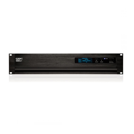
Features Front Panel DESIGN STATUS <Device Name> DEVICE: <Design Name> DESIGN: <Status> STATUS: — Figure 1 — 1. OLED Display – Displays information about the Core's 3. ID button – Locates the Core in Q-SYS Designer GUI settings and status. and Configurator 2. - Page 7 Front Panel OLED Screens DESIGN STATUS Design Status <Device Name> DEVICE: Refer to Figure 3 <Design Name> DESIGN: • Device – The name of the Core as defined in Q-SYS Designer. <Status> STATUS: • Design – The name of the currently running design. •...
- Page 8 Slots A - H There is a total of 8 slots that can accomodate any combination of Q-SYS I/O Cards that are Type 2 format. The status for these cards are shown on the front panel by pressing the NEXT button shown in Figure 3. Slot Mic/Line In H.P.
- Page 9 Dataport Out card Status (CODP4) Slot Dataport Out Refer to Figure 9 (Dataport Out card screen shown.) Mute The Dataport Out card status screen shows the Mute state, Signal Signal presence, and connected amplifier status for both ports. Amp 1 •...
- Page 10 CobraNet card Status (CCN32) Slot Primary Secondary CobraNet Refer to Figure 13 (CobraNet card screen shown) Activity The CobraNet card status screen shows the Activity state, Fault Fault state, In Use state and Conductor state of the Primary and Secondary network ports. In Use •...
-
Page 11: Gpio Pin Assignments
Core 510 product warranty. Connect the QSC DataPort cable from the HD15 connectors on the DataPort Card to the QSC amplifiers. Note that multi-channel amps can spread accross multiple DataPort IO cards, as long as they are in the same Core or IO Frame. - Page 12 GPIO Specifications Relay Pins Normal Current Pins Discription Maximum Voltage, relative to Ground: 30V Maximum Input Range: 0 V to 32 V Maximum Input Range: 0 V to 32 V Maximum Current through Rlay: 1 Amp Analog Input Range: 0 V to 24 V Analog Input Range: 0 V to 24 V Digital Input, Low: 0.8 V maximum Power Pins...
-
Page 13: Rotary Encoder
Directional Motor Control Rotary Encoder +12 V Pin Use PWM and Inverted PWM to control speed and direction. Output issimilar to an H-Bridge topology. Normal or High Current Pin High Current Pin Normal or High 12 V Current Pin Motor –... - Page 14 Q-SYS I/O Card Remove and Replace Procedure This procedure is for Q-SYS Type 2 I/O Cards only. Card installation should only be done by a trained and qualified technician. Tools • Phillips screwdriver • ESD grounded wrist strap — Figure 20 — •...
- Page 15 Q-SYS uses layer 3 (DSCP) QoS. The implementation of this type of QoS on a given network switch can vary depending on the manufacturer and switch model. For more details about network and switch setup, refer to the Help File in Q-SYS Designer. ROTE!: For a list of currently-qualified switches please visit qsc.com and search for “Q-SYS Switches”. TD-000521-00-A...
- Page 16 Dimensions 19 in. 481mm 19 in. 481mm — Figure 25 — TD-000521-00-A...
-
Page 17: Controls And Indicators
Q-SYS Core 510 Series Specifications Description Audio, Video and Control processing engine with integrated I/O (or I/O Frame peripheral for I/O expansion) Operation Mode "Core" mode - Audio, Video and Control processing engine for Q-SYS system with 8, Type 2 I/O card slots for high channel count operation "I/O Frame"... - Page 18 Q-SYS Core 510 Series Specifications Miscellanious Line Voltage 100 VAC - 240 VAC, 50-60 Hz Current Draw 3.7A Max @ 100 VAC (actual current draw depends on configuration options such as; I/O cards and/or Media Drive, DSP and Network loading) °...
-
Page 19: Mailing Address
FAX: +1 (714) 754-6173 © 2017 QSC, LLC. All rights reserved. QSC and the QSC logo are registered trademarks of QSC, LLC in the U.S. Patent and Trademark office and other countries. Q-SYS, Q-LAN and, Q-SYS Designer are trademarks of QSC, LLC. Patents may apply or be pending.
Need help?
Do you have a question about the Q-SYS CORE 510i and is the answer not in the manual?
Questions and answers