Advertisement
Quick Links
V-4072 MINI DOME INDOOR/OUTDOOR
WI-FI HD VIDEO CAMERA
Installation Guide
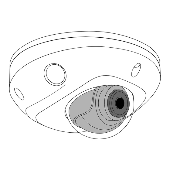
Figure 1: Mini Dome Camera
DESCRIPTION
The V‑4072MD is a 2 Megapixel
indoor/outdoor Wi‑Fi video camera
that allows users to view live and
recorded HD video clips in Virtual
Keypad™.
To activate the camera, you need
an active Dealer Admin account at
dealer.securecomwireless.com.
Compatibility
•
Any active Virtual Keypad
account with SecureCom
Cameras & NVRs enabled
•
V‑4000‑EXT10‑12V 10 foot
extension cable
What is Included?
•
One V‑4072MD camera
•
12 VDC
power supply
•
Hardware pack
1
REMOVE THE COVER
Using the included L‑key to remove
the cover from the camera. Leave
the screws in the cover.
2
MOUNT THE PLATE
1.
After running the power
and/or network wires to
the location of the camera,
thread the wires through the
mounting plate.
2.
Attach the mounting
plate to the ceiling using
the included screws and
standoffs from the small
hardware bag. See Figure 3.
3
ADJUST THE CAMERA
Loosen the adjusment screw to turn the lense in the desired
direction of view using the lense adjustment wrench. Do not
remove the screw completely.
Adjustment
Screw
Figure 4: Camera Range of Motion
Figure 2: Remove Cover
Figure 3: Mounting Plate
Lense
Adjustment
Wrench
Advertisement

Related Manuals for SECURECOM V-4072


Summary of Contents for SECURECOM V-4072
- Page 1 V-4072 MINI DOME INDOOR/OUTDOOR WI-FI HD VIDEO CAMERA Installation Guide REMOVE THE COVER Using the included L‑key to remove the cover from the camera. Leave the screws in the cover. Figure 1: Mini Dome Camera DESCRIPTION The V‑4072MD is a 2 Megapixel indoor/outdoor Wi‑Fi video camera...
- Page 2 WIRE THE CAMERA Before connecting the Ethernet cable or PoE cable, install the waterproof Ethernet cap if desired. Refer to Figure 5. Figure 5: Installing the Waterproof Ethernet Cap PLUG IN THE CAMERA Remove the cap from the end of the power supply.
- Page 3 CONNECT THE CAMERA TO WI-FI Select one of the following connection methods and complete the appropriate steps to configure the camera. ote: SecureCom recommends marking the Ethernet cable from the customer’s router to the WAP to help with network troubleshooting.
- Page 4 Replacement 12 VDC Power Supply Image Sensor 2 MP, 1/2.7” CMOS V-4000-EXT10-12V Extention Cable (10 feet) Network IP Protocol IPv4 Compatibility Wi-Fi Any active Virtual Keypad account with SecureCom Cameras Standard 802.11 B/G/N & NVRs enabled Range Max 165 feet Security WPA, WPA2 Hardware...
Need help?
Do you have a question about the V-4072 and is the answer not in the manual?
Questions and answers