Advertisement
Quick Links
Advertisement

Related Manuals for Sungrow EyeM4


Summary of Contents for Sungrow EyeM4
- Page 1 User Manual...
- Page 3 This manual is intended for the wireless communication module researched and manufactured by Sungrow Power Supply Co., Ltd. This manual is intended to provide users with detailed information on the wireless communication module as well as installation, operation, and maintenance description.
- Page 5 System Diagram Wireless Communication Module Product Appearance Principle Description Function Description Unpacking and Inspection Nameplate Scope of Delivery Storage Installation Location Installation Preparation before Installation Installation Steps Inspection Before Commissioning Commissioning Steps Removal Disposal...
- Page 7 Install the wireless communication module to the inverter bottom. Commission the wireless communication module. Operate and maintain the wireless communication module. Upon receiving, check whether the wireless communication module is damaged during transport. If there is any damage, contact SUNGROW or the forwarding company.
- Page 8 Risk of injury due to incorrect operations! Always observe the instructions in this manual when moving and placing the wireless communication module. Incorrect operations on the wireless communication module can cause minor injury, serious injury, or bruise. Mechanical installation Poor ventilation will compromise the system performance! Ensure that the device is well ventilated and sufficiently cooled down during operation.
- Page 9 Otherwise, SUNGROW shall not be held liable for any damage caused. The components can be damaged due to touching the PCB or other components sensitive to ESD or performing incorrect operations. Avoid unnecessary touch to the PCB.
- Page 10 Observe the following items: Grid connection rules Safety descriptions of other electrical devices...
-
Page 11: System Diagram
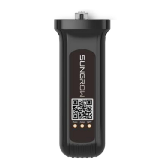
Inverter iSolarCloud management platform Communication accessory port Ethernet EyeM4 Wireless signal Router iSolarCloud Wireless signal Application of the wireless communication module (WLAN) Remote monitoring platform... - Page 12 Wireless Communication Module Product Appearance Appearance * The image shown here is for reference only. The actual product you receive may differ. Indicating the running state of the module Used to connect the module with the inverter Ensure that the wireless communication module is free of visible damages before performing the next operations.
- Page 13 The overall installation flow of the wireless communication module is shown in the following figure 3-1. Start Unpack and check Read the manual Install Store Select installation location Install the wireless communication module Electrical connection Inspection before commissioning Commissioning Troubleshooting Start?
- Page 14 Description of installation flow Read the user manual, especially, the "Safety Instructions". Store wireless communication module properly if it is not installed immediately. Select the optimum installation site. Install the wireless communication module. Electrical connection. Inspection before commissioning. Start the wireless communication module. Troubleshooting.
-
Page 15: Unpacking And Inspection
Check whether the device in the packing case is intact and is free of damage. If there any damage, contact the forwarding company or SUNGROW. Take a picture of the damage, with which we can provide quicker service. Do not dispose of the packing case. It is recommended to store the wireless communication module in its original packing case. -
Page 16: Scope Of Delivery
Store the wireless communication module in proper environment if it is not installed immediately. If otherwise, the wireless communication module may be rusted or its internal components may be damaged, and SUNGROW shall not be held liable for any damage caused. - Page 17 Regularly check the wireless communication module during storage (recommended: once every six months), and replace the packing material if necessary. The packing case must be upright.
-
Page 18: Installation Location
Installation Preparation before Installation Adapter inverter: single-phase residential inverter and three-phase string inverter manufactured by SUNGROW. The inverter has been installed correctly and the DC side can be powered on (For details, refer to the corresponding user manual.). - Page 19 Insert the wireless communication module into the network port (COM) at the bottom of the inverter until it snaps into place with a "Click" sound. If the module is still loose, remove it from the communication port and check whether the port is damaged. If the port the normal, reinsert the wireless communication module.
-
Page 20: Commissioning Steps
Inspection Before Commissioning Check the following items before Environment inspection The wireless communication module is installed in a place convenient for operation and maintenance. Ensure again that the wireless communication module is firmly in place. The installation environment is well-ventilated. The wireless communication module is correctly connected to the inverter. - Page 21 Removal Users can remove the wireless communication module in the reverse steps of electrical connection and mechanical installation. Proceed as follows to unplug the wireless communication module from the inverter. Otherwise, the device may be damaged. Press and hold the buckles on both sides of the wireless communication module and unplug it from the RJ45 interface.
- Page 22 ( ) ( ≤ ) ≥ ≥ ≥ ≥ ≥ ≥...
- Page 23 ( ) ( ≤ ) ≥ ≥ ≥ ≥ ≥ ≥ ≥ ≥ ≥ ≥ ≥ ≥ ≥ ≥ ≥ ≥ ≥ ≥ ≥ ≥ ≥ ≥ ≥ ≥ ≥ ≥...
- Page 24 ( ) ( ) ...
- Page 25 ...
Need help?
Do you have a question about the EyeM4 and is the answer not in the manual?
Questions and answers