Advertisement
SONITONE for UKULELE
Installation GUIDE
www.fishman.com
Read Me First!
Installation of this product is a straightforward
procedure, but we recommend this job only if you
are an experienced repair technician.
Saddle Slot:
Maximum string spacing at saddle: 2.0" (50.8mm)
Control mounting surface
The control module for this system was designed
to fi t in most ukuleles without modifi cation, but we
cannot guarantee a drop-in fi t with all instruments.
Before you begin installation, pre-fi t the control
module in the soundhole, but do not permanently
install at this time. Ideally, the controls should lie fl at
with the housing fl ush to the edge of the soundhole.
Preliminary
1
Drill a
⁄
" hole (3.2mm) in the saddle slot for the
8
pickup wire, no less than .100" (2.5mm) from nearest
string (fi gures 1, 2).
Seal the control module mounting surface
To ensure a strong and reliable bond, you must now
sand, clean and seal the underside of the soundhole
where the preamp will mount.
1. Sand the underside of the soundhole down to
bare wood. Take care to remove all residual lacquer,
polish and dirt.
2. Use mineral spirits to clean the sanded area.
Remove any excess oil, resin and dust from the
exposed wood. Let the area dry before proceeding
to the next step.
3. Seal the exposed wood with an appropriate
coating. Use only a coating that will bond the wood
fi bers and present a hard, uniform surface for the
adhesive. We recommend any of the following:
• Hide glue
• All purpose two-part epoxy
• Cyanoacrylate glue (higher viscosity,
non-instant type)
• Carpenter's glue
Let the area dry before proceeding to the next step.
Figure 1.
Figure 2.
1
Advertisement
Table of Contents

Related Manuals for Fishman SONITONE


Summary of Contents for Fishman SONITONE
- Page 1 SONITONE for UKULELE INSTALLATION GUIDE www.fishman.com Read Me First! Installation of this product is a straightforward procedure, but we recommend this job only if you are an experienced repair technician. Saddle Slot: Maximum string spacing at saddle: 2.0” (50.8mm) Control mounting surface The control module for this system was designed to fi...
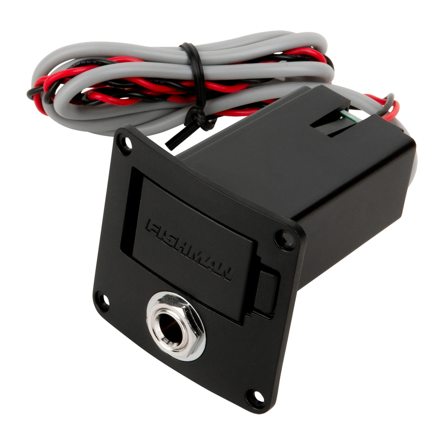
- Page 2 Installation Output jack/battery box installation 1. Once you select the mounting location, affi x the output jack/battery box template and cut out the cavity. 2. Drill a pilot hole for the screw holes. 3. Feed the output and battery wires through the cavity.
Need help?
Do you have a question about the SONITONE and is the answer not in the manual?
Questions and answers