Advertisement
Advertisement

Related Manuals for CANAWELD TIG P201 DC


Summary of Contents for CANAWELD TIG P201 DC
- Page 1 User Manual Model: TIG P201 DC...
- Page 2 Our engineers are continuously working on new equipment to release new models on a regular basis as well as to upgrade our existing line of machines. Canaweld, is in partnership with some of the best European welding and cutting equipment manufacturers, to distribute their machines to the North American market.
-
Page 3: Table Of Contents
TABLE OF CONTENTS EQUIPMENT PACKAGE SECTION 1- SAFETY CAUTIONS & SYMBOLS SECTION 2- INSTALLATION & OVERVIEW SECTION 3- OPERATION OF EQUIPMENT 10-18 SECTION 4- MAINTENANCE & BASIC TROUBLESHOOTING 19-20 SECTION 5- ELECTRICAL SPECIFICATIONS 21-22 SECTION 6- PARTS LIST 23-24 SECTION 7- WARRANTY & SERVICE 25-26... -
Page 4: Equipment Package
TIG P201Dc - WELDER PACKAGE Name Product Number Quantity Machine PLE2380149 Work/Ground Clamp Set ALP1980126 Electrode Holder Set ALP2280095 TIG Torch – Electronic 12 ft TGE0180341 Gas Flow Regulator TLJ1080187 Gas Hose TLJ1080188 Machine Bag TGJ2780145... -
Page 5: Section 1- Safety Cautions & Symbols
SECTION 1- SAFETY CAUTIONS & SYMBOLS CAUTION: READ USER MANUAL Indicates any section that the user must read the manual to fully understand the machine’s characteristics to avoid any hazardous situation. ELECTRIC SHOCK Touching live electrical parts can cause fatal shocks or severe burns. The electrode and work circuit is electrically live whenever the output is on. - Page 6 WELDING FUMES Welding produces fumes and gases. Breathing these fumes and gases can be hazardous to your health. Keep your head out of the fumes stream while welding. Do not breathe the fumes. If inside, ventilate the area and/or use local forced ventilation at the welding point to remove welding fumes and gases.
- Page 7 GASES Dangerous gases can be produced during welding, breathing these gases in can be hazardous to your health. Shut off shielding gas supply when not in use. Always ventilate confined spaces or use approved air-supplied respirator. Do not weld in locations near degreasing, cleaning, or spraying operations. The heat and rays of the arc can react with vapors to form highly toxic and irritating gases.
- Page 8 ESD- ELECTRIC STATIC DISCHARGE An electric static charge can be created during welding and discharged immediately after into any items touched by the welder after welding. Put on grounded wrist strap BEFORE handling boards or parts. Use proper static-proof bags and boxes to store, move, or ship PC boards. MOVING PARTS A number of moving parts may be in typical welding machines such as rollers and fans.
-
Page 9: Section 2- Installation & Overview
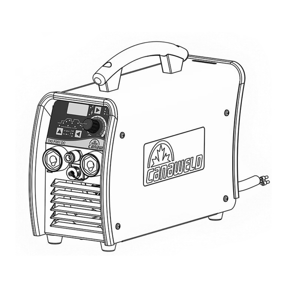
SECTION 2- INSTALLATION AND OVERVIEW INSTALLATION ELECTRICAL The serial number and rating information is located on the bottom of the machine. Use the rating labels to determine input power requirements and rated output. Check whether the voltage value variations are within the acceptable working range with a multi-meter. ... - Page 10 OVERVIEW PRODUCT & DESIGN This is a digital inverter DC pulse TIG welding machine with excellent performance characteristics and advanced technology typically only found on much larger machines. It has various welding functions such as SMAW, DC TIG, pulsed TIG and TIG spot welding (DC or pulsed) allowing the operator to do a very thin to thick variety of metals (will not weld aluminum).
-
Page 11: Section 3- Operation Of Equipment
SECTION 3- OPERATION OF EQUIPMENT OPERATION After being installed according to the prescribed method, switch the power to on (rear panel) and the POWER LED will light and the fan will turn on. (A) Using the push button switch on the top right of the front panel, choose the welding process desired (Tig or Stick) (B) this can only be changed after the led indicator beside the switch has been lit after the machine has been turned on for 3-5 seconds the LED indicator has the symbol of a lightning bolt beside it. - Page 12 TIG OPERATION (A) Insert the welding torch into the (-) output socket on the front panel of the machine, and tighten it clockwise. (B) Connect the electrical plug from the torch to the matching electrical socket on the front of the machine panel.
- Page 13 TIG SETTINGS This selection will require the welder to hold the “start” button on the torch all the time they wish to be welding, once the button is released the welding is stopped and the post gas begins. This selection will allow the welder to push the “start” button on the torch then let go of the button and have continuous welding, push the button a second time to stop the welding and start the post gas.
- Page 14 ERROR CHART E-1: Indicates that an overcurrent has occurred. Restart the machine, and welding can be continued. E-2: Indicates that the main voltage is overly low, welding can be recovered when the main voltage returns into normal range. E-3: Indicates that the main circuit has been overheated, shutting down the machine.
- Page 15 TIG SETTINGS (NON-PULSE) Select DC TIG mode by pressing the welding mode selecting key, select the 2nd mode by pressing the operation mode selecting key. Pre-gas flow time setting function (1st setting) – adjustable from 0-15 sec. Initial current setting function – press button (2 setting) - adjustable from 10-210 (A).
- Page 16 *** 5 setting is only used for TIG PULSE WELDING *** Downslope time setting function – press button (6 setting) – adjustable from 0-60 sec. Pilot arc current setting function – press button (7 setting) – adjustable from 5-210 (A). Post gas - flow time setting function –...
- Page 17 TIG SETTINGS (PULSE) Select DC TIG PULSE mode by pressing the welding mode selecting key, select the 1 setting by pressing the operation mode selecting key. *** All settings are the exact same as in the Non-Pulse procedure with the exception of the 5 setting*** Base current setting function –...
- Page 18 Select STICK mode by pressing the welding mode selecting key, select the 3 setting. Welding current setting function – press button till you reach the 4 setting– adjustable from 10-100 (A). Arc force current setting function – press button – adjustable from 0-180 (A). Stick welding parameter table (for reference only) This table is suitable for mild steel stick welding.
- Page 19 Control Panel 13. Indicator for upslope 1. Welding parameter selecting key 14. Indicator for initial current 2. Operation mode selecting key 15. Indicator for pre-gas flow 3. Welding parameter adjusting knob 16. Indicator for pulse duration ratio 4. Welding mode selecting key 17.
-
Page 20: Section 4- Maintenance & Basic Troubleshooting
SECTION 4- MAINTENANCE & BASIC TROUBLESHOOTING MAINTENANCE Please disconnect power to machine before performing maintenance. Check periodically whether cable connection is in good condition (esp. plugs). Tighten any loose connections. If there is oxidization, remove it with sandpaper and then reconnect. ... - Page 21 (2) Open circuit or loose contact occurs at the joint of output terminal. The electrode holder (1) Replace the electrode holder with The electrode holder is smaller than the a higher current rated electrode becomes very hot. actual working holder. current The output polarity Excessive spatter in MMA...
-
Page 22: Section 5- Electrical Specifications
SECTION 5- ELECTRICAL SPECIFICATIONS SPECIFICATIONS Machine Specifications: TIG Process Input Voltage- Single Phase 230V (+10% / -15%) Maximum Input Amperage Output Current Range 10A - 200A Open Circuit Voltage Output Voltage Range 20.2V - 24V 200A @ 30% Duty Cycle @ 40˚C 160A @ 100% Length: 16 inches Machine Dimensions... - Page 23 Electrical Schematic Diagram...
-
Page 24: Section 6- Parts List
SECTION 6 - PARTS LIST TIGP201DC- Description Product Number Quantity 5 Pin Connector (Female) CGB0680050 5 Pin Connector (Male) CGB0680051 Enclosure - Bottom Plate CGA2880054 Enclosure - Cover CGA2880097 Enclosure - Rear Panel CGA2880166 Enclosure - Front Panel CGA2880170 Cam Switch - Single Phase 32A CGB0780066 CA-MC 35-70Cable Plug (Male) CGB0680070... - Page 25 TIGP201DC- Description Product Number Quantity Screw, Philips 5x15(black) CGA2180216 Solenoid Valve CGB1080227 Solenoid Valve Holder CGA6380228 Strap CGA9980052 Thermo switch CGB2180249...
-
Page 26: Section 7- Warranty & Service
STATEMENT OF LIMITED WARRANTY: Canaweld Inc. warrants to the end user (purchaser) of all new welding and cutting equipment, and accessories (the “Warranted Goods”) that such Warranted Goods will be free of defects in workmanship and material. This warranty is void if Canaweld Inc. - Page 27 (vi) gas lenses, and to the following MIG/MAG torch components (vii) gas nozzles, (viii) tips, (ix) gas lenses, (x) liners, and (xi) drive wheels. Canaweld Inc.’s liability under this warranty shall not exceed the cost of correcting the defect of the Warranted Goods or the cost of replacing them, whichever is less.
Need help?
Do you have a question about the TIG P201 DC and is the answer not in the manual?
Questions and answers