Table of Contents
Advertisement
Advertisement
Table of Contents
Troubleshooting

Related Manuals for CANAWELD MMA 201


Summary of Contents for CANAWELD MMA 201
- Page 1 User Manual Model: MMA 201...
- Page 2 Our engineers are continuously working on new equipment to release new models on a regular basis as well as to upgrade our existing line of machines. Canaweld, is in partnership with some of the best European welding and cutting equipment manufacturers, to distribute their machines to the North American market.
-
Page 3: Table Of Contents
TABLE OF CONTENTS EQUIPMENT PACKAGE SECTION 1- SAFETY CAUTIONS & SYMBOLS SECTION 2- INSTALLATION & SPECIFICATIONS SECTION 3- OPERATION OF EQUIPMENT 10-12 SECTION 4- MAINTENANCE & BASIC TROUBLESHOOTING 13-14 SECTION 5- ELECTRICAL SPECIFICATIONS SECTION 6- PARTS LIST 16-17 SECTION 7- WARRANTY & SERVICE 18-19 NOTES 20-22... - Page 4 MMA 201- WELDER PACKAGE Name Product Number Quantity Machine PLB5180147 Work/Ground Clamp Set ALP1980126 Electrode Holder Set ALP2280095 TIG Torch with Gas Valve TGE0180334 Gas Flow Regulator TLJ1080187 Gas Hose TLJ1080188 Machine Bag TGJ2780145...
-
Page 5: Section 1- Safety Cautions & Symbols
SECTION 1- SAFETY CAUTIONS & SYMBOLS CAUTION: READ USER MANUAL Indicates any section that the user must read the manual to fully understand the machine’s characteristics to avoid any hazardous situation. ELECTRIC SHOCK Touching live electrical parts can cause fatal shocks or severe burns. The electrode and work circuit is electrically live whenever the output is on. - Page 6 WELDING FUMES Welding produces fumes and gases. Breathing these fumes and gases can be hazardous to your health. Keep your head out of the fumes stream while welding. Do not breathe the fumes. If inside, ventilate the area and/or use local forced ventilation at the welding point to remove welding fumes and gases.
- Page 7 GASES Dangerous gases can be produced during welding, breathing these gases in can be hazardous to your health. Shut off shielding gas supply when not in use. Always ventilate confined spaces or use approved air-supplied respirator. Do not weld in locations near degreasing, cleaning, or spraying operations. The heat and rays of the arc can react with vapors to form highly toxic and irritating gases.
- Page 8 ESD- ELECTRIC STATIC DISCHARGE An electric static charge can be created during welding and discharged immediately after into any items touched by the welder after welding. Put on grounded wrist strap BEFORE handling boards or parts. Use proper static-proof bags and boxes to store, move, or ship PC boards. MOVING PARTS A number of moving parts may be in typical welding machines such as rollers and fans.
-
Page 9: Section 2- Installation & Specifications
SECTION 2- INSTALLATION, OVERVIEW & SPECIFICATIONS INSTALLATION ELECTRICAL The serial number and rating information is located on the bottom of the machine. Use the rating labels to determine input power requirements and rated output. Check whether the voltage value variations are within the acceptable working range with a multi-meter. ... - Page 10 Set of heavy duty connector and ground cable which is able to connect to other Dinse system ºF 40 ºC. Heavy duty machine (150 A in 100 % duty cycle in 104 FUNCTION Hot start arc ignition application is a built –in function: allows for the arc ignition in MMA welding making ignition easier and more reliable.
-
Page 11: Section 3- Operation Of Equipment
SECTION 3- OPERATION OF EQUIPMENT OPERATION After being installed according to the prescribed method, and the power switch being switched on, the machine is started with the power LED on and the fan working. Pay attention to the polarity when making connections. An unstable arc, spatter, and electrode sticking could happen if improper mode is selected, exchange the polarity if necessary. - Page 12 Welding parameter table (for reference only) This table is suitable for mild steel stick welding. For other materials, consult related materials and welding process for reference. Electrode diameter (mm) Recommended welding current (A) Recommended welding voltage(V) 60 - 100 22.4 - 24.0 80 - 120 23.2 - 24.8 108 - 148...
-
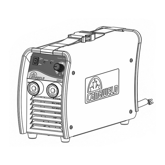
Page 13: Control Panel
Control Panel Front Panel 1) Welding Process Switch(STICK) 2) Welding Process Switch(TIG) 3) Main voltage LED 4) Thermostatic protection LED 5) Welding current adjustment STICK Welding: Switch Position 1 Then adjust your welding Voltage with 5. TIG Welding: Switch position 2 Adjust your welding current with 5. -
Page 14: Section 4- Maintenance & Basic Troubleshooting
SECTION 4- MAINTENANCE & BASIC TROUBLESHOOTING MAINTENANCE Please disconnect power to machine before performing maintenance. Check periodically whether cable connection is in good condition (esp. plugs). Tighten any loose connections. If there is oxidization, remove it with sandpaper and then reconnect. ... -
Page 15: Troubleshooting
TROUBLESHOOTING Problem Remedy No welding output; unit completely inoperative; 1) Be sure power cord is plugged in and that ready light (LED) Off. receptacle is receiving input power. 2) Check if the Power switch is in ON position. 3) Check and replace line fuse(s), if necessary, or reset circuit breaker. -
Page 16: Section 5- Electrical Specifications
SECTION 5- ELECTRICAL SPECIFICATIONS Machine Specifications: Input Voltage- Single Phase 230V , 50/60Hz (+10 / -15%) Maximum effective primary current (�� 24 A 1 ������ Maximum Primary Current 43 A Open circuit Voltage 64 V Output Current Range 10A - 200A Output Voltage Range 20.4V –... -
Page 17: Section 6- Parts List
Flat Washer (outer diameter 12mm/inner diameter 5mm) CGA2380101 Front Panel Sticker CGA6180114 Gland CGA6480122 Ground Clamp 300 A (copper) TGJ0580125 Insulation Paper- MMA 201 CGA7680137 Knob (Black), 20mm CGB1880142 Nut (potentiometer), D=9mm CGA2280152 Cage Nut CGA2280156 Mother Board 200 A, 230 V... - Page 18 Rocker Switch CGB0780236 Terminal, Crimping, for Welding Cable AWG 4 (8mm/25mm) CGB0880240 Terminal, Double Quick CGB0880241 Terminal, Fork CGB0880242 Terminal, Quick (Red) CGB0880245 Terminal, Quick (Yellow) CGB0880246 Terminal, Ring- 1AWG16 CGB0880248 Thermo switch CGB2180249...
-
Page 19: Section 7- Warranty & Service
STATEMENT OF LIMITED WARRANTY: Canaweld Inc. warrants to the end user (purchaser) of all new welding and cutting equipment, and accessories (the “Warranted Goods”) that such Warranted Goods will be free of defects in workmanship and material. This warranty is void if Canaweld Inc. - Page 20 (vi) gas lenses, and to the following MIG/MAG torch components (vii) gas nozzles, (viii) tips, (ix) gas lenses, (x) liners, and (xi) drive wheels. Canaweld Inc.’s liability under this warranty shall not exceed the cost of correcting the defect of the Warranted Goods or the cost of replacing them, whichever is less.
-
Page 21: Notes
NOTES... - Page 22 NOTES...
-
Page 23: Notes
NOTES...
Need help?
Do you have a question about the MMA 201 and is the answer not in the manual?
Questions and answers