Table of Contents
Advertisement
Advertisement
Table of Contents
Troubleshooting

Related Manuals for CANAWELD MIG/MMA 201


Summary of Contents for CANAWELD MIG/MMA 201
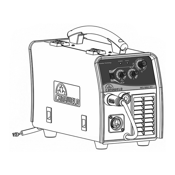
- Page 1 User Manual Model: MIG/MMA 201...
- Page 2 Our engineers are continuously working on new equipment to release new models on a regular basis as well as to upgrade our existing line of machines. Canaweld, is in partnership with some of the best European welding and cutting equipment manufacturers, to distribute their machines to the North American market.
-
Page 3: Table Of Contents
TABLE OF CONTENTS EQUIPMENT PACKAGE SECTION 1- SAFETY CAUTIONS & SYMBOLS SECTION 2- INSTALLATION & SPECIFICATIONS SECTION 3- OPERATION OF EQUIPMENT 10-13 SECTION 4- MAINTENANCE & BASIC TROUBLESHOOTING 14-15 SECTION 5- ELECTRICAL SPECIFICATIONS 16-17 SECTION 6- PARTS LIST 18-19 SECTION 7- WARRANTY & SERVICE 20-21 NOTES... - Page 4 MIG / MMA 201- WELDER PACKAGE Name Product Number Quantity Machine PLC7580146 Work/Ground Clamp Set ALP1980126 Electrode Holder Set ALP2280095 MIG Torch TGD0180150 Gas Flow Regulator TLJ1080187 Gas Hose TLJ1080188 Machine Bag TGJ2780145...
-
Page 5: Section 1- Safety Cautions & Symbols
SECTION 1- SAFETY CAUTIONS & SYMBOLS CAUTION: READ USER MANUAL Indicates any section that the user must read the manual to fully understand the machine’s characteristics to avoid any hazardous situation. ELECTRIC SHOCK Touching live electrical parts can cause fatal shocks or severe burns. The electrode and work circuit is electrically live whenever the output is on. - Page 6 WELDING FUMES Welding produces fumes and gases. Breathing these fumes and gases can be hazardous to your health. Keep your head out of the fumes stream while welding. Do not breathe the fumes. If inside, ventilate the area and/or use local forced ventilation at the welding point to remove welding fumes and gases.
- Page 7 GASES Dangerous gases can be produced during welding, breathing these gases in can be hazardous to your health. Shut off shielding gas supply when not in use. Always ventilate confined spaces or use approved air-supplied respirator. Do not weld in locations near degreasing, cleaning, or spraying operations. The heat and rays of the arc can react with vapors to form highly toxic and irritating gases.
- Page 8 ESD- ELECTRIC STATIC DISCHARGE An electric static charge can be created during welding and discharged immediately after into any items touched by the welder after welding. Put on grounded wrist strap BEFORE handling boards or parts. Use proper static-proof bags and boxes to store, move, or ship PC boards. MOVING PARTS A number of moving parts may be in typical welding machines such as rollers and fans.
- Page 9 SECTION 2- INSTALLATION and OVERVIEW INSTALLATION ELECTRICAL The serial number and rating information is located on the bottom of the machine. Use the rating labels to determine input power requirements and rated output. Check whether the voltage value variations are within the acceptable working range with a multi-meter. ...
- Page 10 OVERVIEW PRODUCT & DESIGN Our unique electric structure and air channeling design in this series of welding machines are designed to increase the heat dissipation of the power device improving the duty cycle of the machine. The unique heat dissipation design leads to less damage done to the power source and control circuits from overheating due to dust build up from air inducted by fan.
-
Page 11: Section 3- Operation Of Equipment
SECTION 3- OPERATION OF EQUIPMENT OPERATION After being installed according to the prescribed method, switch the power to on (rear panel) and the POWER LED will light and the fan will turn on. Using the rocker switch on the front panel choose the welding process desired (MIg or Stick). ... - Page 12 MIG OPERATION (Flux Core Wire Welding) (A) Insert the welding torch into the output socket on the front panel of the machine, and tighten it. (B) Insert the cable plug from the work / ground clamp into the (+) output terminal on the front panel of the welding machine, and tighten it clockwise.
- Page 13 MIG welding parameter table (for reference only) This table is suitable for mild steel MIG/MAG welding. For other materials, consult related materials and welding process for reference. Spray arc Intermediate range Short arc Wire size (mm) 140 - 180 23 – 28 110 –...
-
Page 14: Control Panel
Stick welding parameter table (for reference only) This table is suitable for mild steel stick welding. For other materials, consult related materials and welding process for reference. Electrode diameter (mm) Recommended welding current (A) Recommended welding voltage(V) 60 - 100 22.4 - 24.0 80 - 120 23.2 - 24.8... -
Page 15: Section 4- Maintenance & Basic Troubleshooting
SECTION 4- MAINTENANCE & BASIC TROUBLESHOOTING MAINTENANCE Please disconnect power to machine before performing maintenance. Check periodically whether cable connection is in good condition (esp. plugs). Tighten any loose connections. If there is oxidization, remove it with sandpaper and then reconnect. ... -
Page 16: Basic Troubleshooting
BASIC TROUBLESHOOTING Problem Causes Remedy There is output current when pulling the torch The wire feeder is clogged. Unclog it. trigger, gas feeding but there is no wire feeding out. The wire feeder has failed. Repair / replace it. The control PCB or wire feeding Replace it. -
Page 17: Section 5- Electrical Specifications
SECTION 5- ELECTRICAL SPECIFICATIONS Machine Specifications: MIG/FCAW Process Input Voltage- Single Phase 230V (+10 / -15%) Maximum Input Amperage Output Current Range 40A - 200A Open Circuit Voltage Output Voltage Range 16V - 24V 200A @ 35% Duty Cycle @ 40˚C 190A @ 60% 170A @ 100% Length: 20 inches... - Page 18 Electrical Schematic Diagram...
-
Page 19: Section 6- Parts List
Flat Washer (outer diameter 16mm/inner diameter 6.5mm) CGA2380106 Flat Washer (outer diameter 24mm/inner diameter 14mm) CGA2380107 Flat Washer (outer diameter 8mm/inner diameter 4mm) CGA2380103 Front Panel Sticker for MIG/MMA 201 machine CGA6180110 Gas Fitting MALE CGA3180116 Gas Fitting FEMALE CGA3180117... - Page 20 MMA/MIG201 Name Product Number - Quantity Nut M9.5mm CGA2280158 Package 200A, MIG/MMA 201 CGC9180162 Panel Socket (Female) CA-FF 35-70 CGB0680064 Enclosure Front Panel- MIG CGA2880164 Enclosure Vertical Panel –MIG CGA2880167 Enclosure-Rear Panel- MIG CGA2880168 Plastic Holder CGA6380171 Plastic Lock CGA9980172 Plastic Zip Tie 3.6*150mm White KSS-CV-150...
-
Page 21: Section 7- Warranty & Service
STATEMENT OF LIMITED WARRANTY: Canaweld Inc. warrants to the end user (purchaser) of all new welding and cutting equipment, and accessories (the “Warranted Goods”) that such Warranted Goods will be free of defects in workmanship and material. This warranty is void if Canaweld Inc. -
Page 22: Notes
(vi) gas lenses, and to the following MIG/MAG torch components (vii) gas nozzles, (viii) tips, (ix) gas lenses, (x) liners, and (xi) drive wheels. Canaweld Inc.’s liability under this warranty shall not exceed the cost of correcting the defect of the Warranted Goods or the cost of replacing them, whichever is less. - Page 23 NOTES...
Need help?
Do you have a question about the MIG/MMA 201 and is the answer not in the manual?
Questions and answers